The rf amplifier, mixer, and local oscillator stages form the rf tuning section, generally called the front end or tuner. This section selects the picture and sound signals of the desired station by converting the rf signal frequencies of the selected channel to the intermediate frequencies of the receiver. Only those frequencies in the IF passband can be amplified enough for you to see a picture and hear the sound.
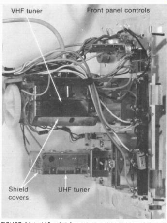
There are separate VHF and UHF tuners, as shown in Fig. 24-1, each on a separate subchassis. For either tuner, it is the local oscillator that tunes in the desired station. The reason is that the oscillator frequency determines which rf signal frequencies become IF signal frequencies to be amplified by the receiver. The fine-tuning control varies the oscillator frequency slightly for exact tuning for the best picture and sound.
Color receivers usually have an automatic fine tuning (AFT) circuit to control the oscillator frequency. More details of the tuner circuits are described in the following topics:
24-1 Tuner operation
24-2 Functions of the rf amplifier
24-3 Rf amplifier circuits
24-4 The mixer stage
24-5 The local oscillator
24-6 Automatic fine tuning (AFT)
24-7 Types of rf tuners
24-8 VHF tuner circuits
24-9 UHF tuner circuits
24-10 Cable television channels
24-11 Varactors for electronic tuning
24-12 Rf alignment
24-13 Remote tuning
24-14 Tuner troubles
FIGURE 24-1 MOUNTING ASSEMBLY WITH VHF AND UHF TUNERS. LENGTH OF VHF TUNER
IS 4 IN (MAGNAVOX CO.)
24-1 Tuner Operation
The VHF tuner is for channels 2 to 13, with frequencies from 54 to 216 MHz in the VHF band of 30 to 300 MHz. Channel 1 is not assigned to television broadcasting anymore, but this position on the station selector switch is generally used to turn on the UHF tuner. The UHF channels are 14 to 83, with frequencies of 470 to 890 MHz in the UHF band of 300 to 3,000 MHz. For UHF operation, the VHF tuner serves as an IF amplifier for the output of the UHF tuner. See the block diagram illustrating tuner operation in Fig. 24-2.
Referring to the rf amplifier on the VHF tuner in Fig. 24-2, its input is the rf signal from the antenna. The input circuit is tuned to the 6-MHz band of the selected channel to amplify its rf picture and sound carrier signals. The amplified output, still at the rf channel frequencies, is coupled into the mixer stage. Included are the FM sound carrier and the AM picture carrier with its multiplexed color subcarrier for a color program. In the mixer stage, the rf signals beat with the oscillator output for conversion to the intermediate frequencies. The one oscillator frequency beats with both picture and sound rf carrier signals to produce the IF signals.
The local oscillator frequency beats above the rf signal frequencies. For the example in Fig. 24-2, tuning in channel 4, the oscillator is at 67.25 + 45.75 = 113 MHz.
When the station selector switch is varied, the resonant circuits for the rf amplifier and mixer input are changed to the 6-MHz band for each channel. At the same time, the oscillator frequency is changed to the value that can beat the rf picture and sound carrier frequencies to the IF values of 45.75 MHz and 41.25 MHz. The circuits are on a common shaft for ganged tuning.
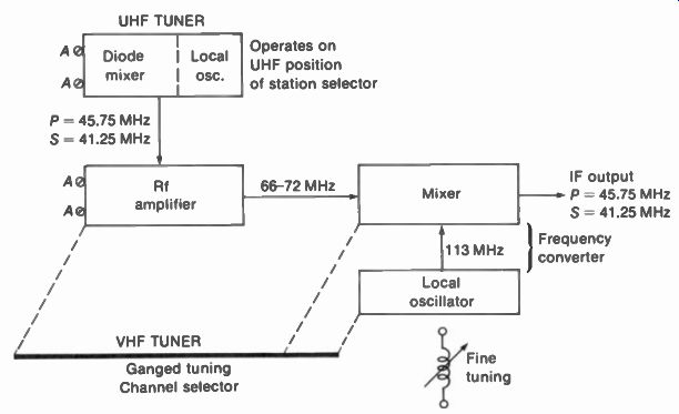
FIGURE 24-2 BLOCK DIAGRAM OF VHF TUNER. SET FOR CHANNEL 4 AT 66 TO 72 MHz
NOTE THAT THE IF OUTPUT OF THE UHF TUNER IS FED TO THE VHF TUNER FOR UHF OPERATION
ONLY
Tuner connections. As illustrated in Fig. 24-3, the VHF tuner needs connecting leads for B+ voltage, AGC bias, and heater voltage for rubes.
The IF output is connected to the IF amplifier by a short length of coaxial cable with a plug at the tuner end. Output from the UHF tuner also has a coaxial cable that plugs into the VHF tuner. Since there is a terminal strip for the electrode voltages and coaxial plug connections for the signal leads, it usually is relatively easy to disconnect the tuner for replacement.
UHF tuner. This tuner is usually solid state, so that it only needs one B+ lead from the VHF tuner. In Fig. 24-2 only a UHF mixer and oscillator are included, without an rf amplifier. The UHF antenna signal is coupled into the diode mixer. The output of the UHF oscillator is also coupled into this stage. The oscillator beats with the UHF channel frequencies to produce IF output at 45.75 MHz for the picture carrier and 41.25 MHz for the sound carrier. For channel 21 at 512 to 518 MHz, as an example, P is 513.25 MHz and S is 517.75 MHz. The UHF oscillator then is at 559 MHz.
Then the IF picture and sound signals from the UHF mixer are coupled to the VHF tuner. These rf and mixer stages operate as IF amplifiers when the VHF station selector is set to the UHF position. The VHF oscillator is disabled and the rf tuned circuits are changed to IF tuned circuits.
Turret tuner. See Fig. 24-4. This VHF tuner has coil strips for each channel mounted with spring clips on a drum or turret. Rotating the drum connects any strip to a set of fixed contacts in side the tuner subchassis. The strip has coils for the rf amplifier, mixer, and oscillator tuned circuits for one channel. On the UHF position, B+ voltage is removed from the VHF oscillator, while the rf amplifier and mixer input circuits are tuned to the IF band.
Rotary-switch tuner. See Fig. 24-5. This VHF tuner has rotary wafer switches for each stage.
The oscillator section is at the front. Each wafer has contacts for 12 VHF channels plus the channel 1 position for UHF operation. All the wafers are ganged on one common shaft.
Manual fine tuning control. The usual method of manual fine tuning is to push in the control to engage a plastic wheel that turns a slug in the oscillator coil. Adjust to the point where you see sound bars and then back off the tuning slightly for the best picture. With color, tune for maximum color without 920-kHz beat in the picture.
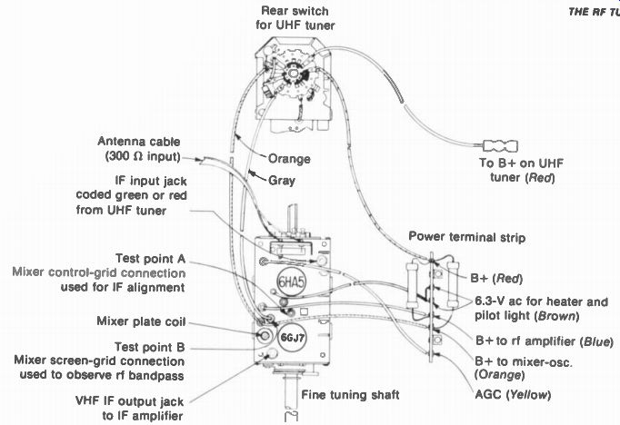
FIGURE 24-3 CONNECTIONS ON VHF TUNER (ZENITH 750 SERIES
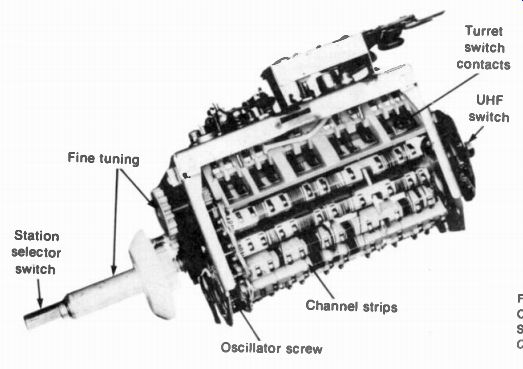
FIGURE 24-4 TURRET TUNER WITH COIL STRIPS FOR EACH CHANNEL SHIELD COVER OFF
(MAGNAVOX CO)
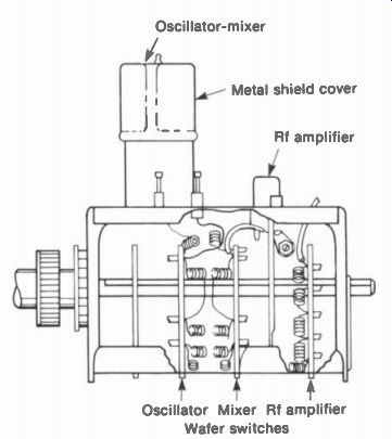
FIGURE 24-5 ROTARY-SWITCH TUNER WITH WAFER SWITCHES FOR EACH STAGE.
Mechanical detent. The VHF tuner has a wheel with notches for each position. Each notch, or detent, holds the switch steady for good contact by means of a detent spring. The tuner should be tight to turn as it clicks into position on each channel. Good connections at the switch contacts are essential for the very high signal frequencies.
Mechanical troubles. The two most common problems with VHF tuners are a weak detent spring and dirty contacts. All the switch contacts are silver plated for very low resistance. However, silver tarnishes as it becomes oxidized by the air. After a year or two, the tuner contacts often must be cleaned, preferably with a commercial tuner spray. Remove the tuner cover, which snaps off, to spray all the switch contacts.
Then rotate the switch in both directions a few times.
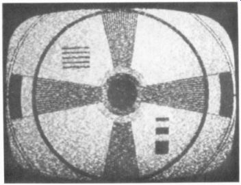
FIGURE 24-6 SNOW IN PICTURE. CAUSED BY WEAK RF SIGNAL.
Indications of poor contact at the switches are: (1) moving the station selector slightly improves the picture, or the switch must be "jiggled"; (2) rotating the switch in one direction tunes in the station better than the opposite rotation. When the switch feels tight, the intermit tent connections are probably caused by dirty contacts. If the switch is loose, the detent spring should be replaced.
24-2 Functions of the RF Amplifier
The main purpose of the amplifier is to provide enough rf signal into the mixer for a clean picture without snow. Random noise generated in the receiver circuits is amplified to produce the white speckles called snow in the picture (Fig. 24-6). The mixer circuit generates the most noise because of its heterodyning function. Furthermore, the mixer noise is amplified in the IF section. For this reason, the noise generated in the mixer stage is called IF noise or receiver noise.
If there is sufficient rf signal into the mixer, the signal-to-noise ratio will be high enough to produce a picture without visible snow. The required signal-to-noise ratio is approximately 30:1. A typical value of receiver noise at the input is 15 µV. With a low-noise rf amplifier, a signal level of 450 µV or more at the receiver input can provide a picture without snow.
Any time you see snow in the picture, it shows that the mixer noise is being amplified in the IF and video amplifiers. The trouble is weak rf signal, either in the rf amplifier or in the antenna input.
Oscillator radiation. The rf amplifier provides the only isolation between the local oscillator stage and the antenna input connections. Any oscillator output coupled to the antenna can be radiated to produce interference in nearby receivers. Therefore, the rf amplifier also serves as a buffer stage to minimize oscillator radiation.
It should be noted, though, that the oscillator output can also be radiated by the receiver chassis. This is the reason why a separate chassis-ground return is generally used for the tuner circuits. The FCC specifies the maximum radiation at a distance of 100 ft or more from the receiver. These limits for field strength are 50 to 150 µV/m in the VHF band and 500 µVim in the UHF band.
Oscillator radiation produces diagonal lines in other receivers, just like any cw interference pattern. However, the use of 45.75 MHz for the picture IF carrier in the receiver results in oscillator frequencies that are not in the band of any VHF channel.
Image frequencies. Practically all the receiver selectivity to reject the frequencies of adjacent channels is in the IF section. However, superheterodyne receivers have the problem of rejecting interfering rf signals that can beat with the local oscillator to produce frequencies within the IF passband. These are image frequencies because they are as much above the oscillator frequency as the desired signal frequency is below it. As an example, in Fig. 24-2 the oscillator frequency is at 113 MHz for the picture carrier of 113-45.75 = 67.25 MHz for channel 4.
The image frequency then is 113 + 45.75 = 158.75 MHz.
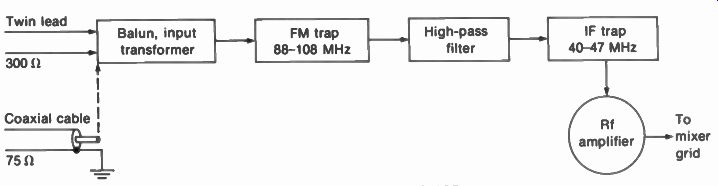
FIGURE 24-7 BLOCK DIAGRAM OF INPUT CIRCUIT FOR RF AMPLIFIER STAGE.
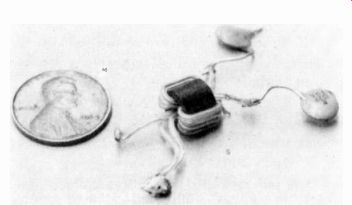
FIGURE 24-8 BALANCING TRANSFORMER OR BALUN FOR RF INPUT CIRCUIT.
Rf selectivity. Another function of the rf amplifier is to prevent reception of spurious signals, which have no relation to the desired signal frequency. Especially important is rejecting rf signals in the IF passband. Any interference in the range of 40 to 47 MHz that enters the IF amplifier will be amplified along with the desired signal.
Figure 24-7 illustrates the wave traps and filter generally used in the rf amplifier input to improve rf selectivity and prevent interference.
These circuits include:
1. IF wave trap to reject 40 to 47 MHz.
2. High-pass filter cutting off at 50 MHz. All frequencies below 54 MHz for channel 2 should be rejected.
3. FM trap to reject the commercial broadcast band of 88 to 108 MHz. These frequencies can cause interference in channel 2.
The rf tuned circuits are often called the preselector, indicating that they select only the des red signal.
Input impedance. A definite value must be provided at the antenna terminals on the receiver, which is the input circuit for the rf amplifier. The purpose is to match the characteristic impedance of the transmission line from the antenna. Without this match, the length of the line would be critical. The standard impedance is 300 ohm for television receivers and FM receivers, to match 300-ohm twin lead. Most receivers now also have a grounded jack with 75-ohm impedance for coaxial cable. The impedance of 300 ohm balanced, or 75 ohm single-ended to ground, is provided by a balancing transformer (Fig. 24-8).
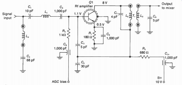
FIGURE 24-9 TRANSISTOR RF AMPLIFIER CIRCUIT.
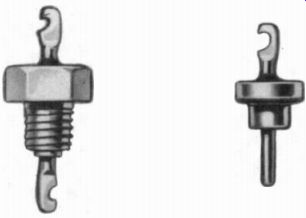
FIGURE 24-10 FEEDTHROUGH BYPASS CAPACITORS. LENGTH ABOUT IN. WITH LEADS.
24-3 RF Amplifier Circuits
The transistor stage in Fig. 24-9, the triode tube in Fig. 24-11, the cascode twin-triode in Fig. 24-12, and the dual-gate field-effect transistor (FET) in Fig. 24-13 are typical. Common triode tubes for the rf amplifier are the 6DS4 nuvistor, 6HA5, 2FH5, and 3GK5. Triodes generate less tube noise than pentodes because the internal noise is increased by partition of the space current with more grids.
Transistor rf amplifier. The rf stage in Fig. 24-9 uses an NPN transistor with a grounded shield.
The input circuit to the base is tuned to the desired channel by the parallel resonant circuit with L„, C _p and C. In the collector output circuit, the double-tuned transformer Tr has L2 and L3 tuned by C7 and C. The collector supply of 10 V is fed through the RC decoupling filter of R 3 with bypass C,„. Circles shown at the connections for L„, L2, and L 3 indicate that these coils are switched for each channel. The amplified rf output goes to the input of the mixer stage.
The transistor operates as a class A amplifier, usually with AGC bias. Note that in Fig. 24-9, the AGC bias is fed to the base of Q1 through the RC decoupling filter of R, with bypass C,.
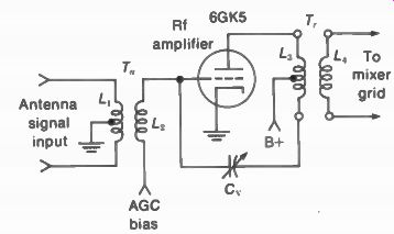
FIGURE 24-11 TRIODE RE AMPLIFIER CIRCUIT WITH NEUTRALIZATION.
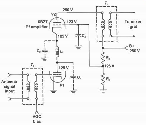
FIGURE 24-12 CASCODE RF AMPLIFIER CIRCUIT USING TWIN-TRIODE WITH DC COUPLING.
The emitter voltage of 0.5 V on Q1 is produced by /,.: through R,.
Also, the AGC bias at the base is 1.1 V. Then the net bias for V8, is 1.1 - 0.5 = 0.6 V.
Feedthrough bypass capacitors. The symbol for C, and C,„ in Fig. 24-9 indicates a feedthrough construction, generally used for bypassing on the B+ and AGC lines into the rf tuner. As shown in Fig. 24-10, one side of the capacitor is the metal base, which is mounted on the chassis. The two end terminals are both connected internally to the opposite capacitor plate. This construction features very low inductance. In addition, it prevents radiation of signal from the leads that must go through the metal case of the tuner. Furthermore, the end terminal outside the chassis can serve as a convenient looker point for connecting test equipment.
Rf neutralization. A triode tube or transistor for the rf amplifier has internal feedback from output to input, which can make the stage oscillate. To prevent oscillations, the rf amplifier often has a neutralizing circuit. Neutralization requires feeding back part of the output signal with opposite polarity from the internal feedback. In Fig. 24-9, C is the neutralizing capacitor and feeds signal back from the collector circuit to the base.
Neutralized triode rf amplifier. In Fig. 24-11, the neutralizing capacitor C, feeds back part of the plate signal to the control grid. Note that the plate coil L3 is tapped to provide signal at the low end for neutralizing voltage. In the input circuit of the rf amplifier, L1 and L2 are tuned by stray capacitances to the frequencies of the desired channel. Similarly, L„ and L4 in the plate circuit provide the amplified rf signal into the mixer stage.
The conventional circuit in Fig. 24-11 is called a grounded-cathode amplifier. Input signal is applied to the control grid, with respect to the common cathode, while the amplified output signal is from the plate. It is also possible to use a grounded-grid amplifier. Then the input signal is applied to the cathode instead of the control grid, which is grounded for signal. The grounded-grid rf amplifier generally does not require a neutralizing circuit because there is no signal voltage at the control grid.
Cascode rf amplifier circuit. See Fig. 24-12. A twin-triode tube combines a grounded-cathode stage V1 driving V2 as a grounded-grid amplifier.
The V1 stage has AGC bias, which is dc-coupled to V2. This circuit has the gain of a pentode but the low noise of a triode. The V1 stage is not neutralized because it has a very low plate load impedance. Most of the gain is in the grounded grid stage V2, which needs no neutralization.
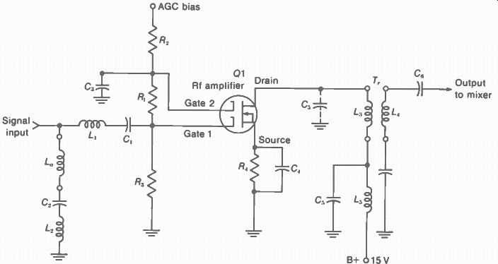
FIGURE 24-13 RF AMPLIFIER USING FET WITH DUAL GATES.
Note that V1 and V2 are in series for dc supply voltage. The plate current of V1 is the cathode current of V2. As a result, the plate cathode voltage for each tube is one-half the B+ supply voltage. Note that 123 V is provided at the grid of V2 by the R, R„ voltage divider. Then the V2 grid-cathode bias is 123 - 125 = -2 V. C„ is a bypass to return the grid of V2 to ground for rf signal.
The signal input is applied by T„ to the grid of V1. Its plate load impedance is the resonant circuit formed by L k, C _p., and C„. They form a z-type filter coupling circuit. The resonant rise in voltage across CA . provides signal input for the cathode of the grounded-grid stage V2. In the output circuit, the amplified rf signal in the plate circuit of V2 is coupled by T,. to the mixer grid.
The rf tuning for each station is changed only for the transformers T„ and T, as the network between V1 and V2 provides a resonant response broad enough to include all 12 VHF channels.
FET rf amplifier. The circuit in Fig. 24-13 uses a field-effect transistor (FET) with dual gates for its N channel. An FET features very high input impedance, compared with junction transistors, arm has low noise. The drain electrode corresponds to the plate or collector, the gate is like the control grid or base, and the source has the function of the cathode or emitter. The main ad vantage of an FET or amplifier is that it can operate without overload distortion for a wide range of signal input voltages.
This dual-gate FET circuit is similar to a cascode amplifier. Gate 1 has input signal as a grounded-source stage, while gate 2 is for a grounded-gate stage. C, is an rf bypass. The amplified output signal from the drain is coupled by T,. to the mixer stage. This FET rf amplifier does not need neutralization because of the grounded-gate stage. The AGC bias voltage applied to gate 2 and gate 1 may vary from -5 V for strong signals to +6 V for weak signals.
Rf response curve. The graph of relative gain in Fig. 24-14 shows that the rf amplifier has 6 MHz bandwidth for each selected channel. The signals amplified are the sound carrier S and the picture carrier P with its multiplexed 3.58-MHz color subcarrier signal C. This overall rf response is from the antenna input terminals to the mixer grid. Note that the curve is shown for channel 10 at 192 to 198 MHz because this channel is generally used for rf alignment. Each channel should have this response within approximately - ± -10 percent for the relative amplitudes of P and S.
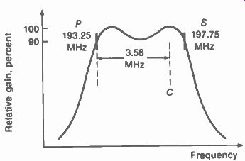
FIGURE 24-14 TYPICAL RF RESPONSE CURVE. FROM ANTENNA TO MIXER. BANDWIDTH
OF 6 MHz SHOWN FOR CHANNEL 10 AT 192 TO 198 MHz.
24-4 The Mixer Stage
The function of this circuit is to convert the rf signal frequencies to the IF passband of the receiver. The two inputs required are (1) rf signal and (2) oscillator injection voltage. The mixer output is produced by heterodyning or beating the oscillator voltage with the rf signal.
As a result, the difference frequencies provide the IF signal.
Note that the one oscillator signal beats with both the picture and sound carriers.
Therefore, the separation between the two carrier frequencies in the IF output is the same 4.5 MHz as in the rf signals. Also, the color sub carrier signal is 3.58 MHz from the picture carrier frequency in either the rf signal or the IF signal.
The mixer circuit generally uses a pentode tube as in Fig. 24-15 or a transistor as in Fig. 24-16 for the VHF tuner. In the UHF tuner, the mixer is usually a crystal diode, which has less noise and requires less oscillator voltage.
There is no AGC bias on the mixer stage.
Rectification in the converter circuit. The mixer stage combined with the local oscillator can be considered as a frequency converter.
Rectification in the mixer is necessary, as the nonlinear response produces the beat frequencies. Therefore, the mixer is the first detector in the superheterodyne receiver, rectifying the combination of rf signal and oscillator voltage to provide IF signal output. In a tube, the grid cathode circuit serves as a diode rectifier; in a transistor, the base-emitter junction is a diode rectifier.
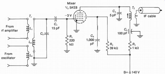
FIGURE 24-15 PENTODE MIXER CIRCUIT
The oscillator must provide enough injection voltage to cause nonlinear amplification.
For a pentode mixer tube, the oscillator injection voltage is about 3 V peak value, which is very large compared with millivolts of rf signal.
The ratio of IF signal output to rf signal input is the conversion gain of the mixer stage.
A typical gain is 6. With 2-mV rf signal input, as an example, the IF signal output 1s6 x 2 = 12 mV. Pentode mixer circuit. The pentode in Fig. 24-15 is combined in a single tube with a triode oscillator, not shown here. The two input signals for the mixer are oscillator output coupled by L, and rf signal coupled by L,. Grid-leak bias of -3 V is produced by the oscillator injection voltage. The mixer rf input circuit is tuned to the selected channel by L„ with C2.
Because of nonlinear operation in the mixer stage, the output plate current contains the IF signal. The plate circuit of the mixer is tuned to the IF band by the first IF transformer T _p with the capacitance of C4. The secondary of T, supplies IF signal to the tuner output jack for the IF cable to the main chassis.
In the plate circuit, R. and C, form a decoupling filter in the B+ line. In the screen-grid circuit, R, is a dropping resistor to provide the desired screen voltage. C„ is the bypass for R,. Transistor mixer circuit. In Fig. 24-16, rf signal is coupled to Q1 by the rf input transformer T r. The primary L and secondary L 2are tuned by C, and C, for the selected channel. C, is a coupling capacitor and blocks the dc bias at the base. Oscillator voltage is injected into the base circuit by capacitive coupling. C3 and C„ form a capacitive voltage divider, with the oscillator voltage across C, for the mixer.
In the emitter circuit, R, and C6 produce emitter bias. This is reverse voltage for the emitter-base junction of the NPN transistor. However, the R,R, voltage divider provides positive forward bias for the base. The input junction at the base serves as a diode rectifier to heterodyne the rf and oscillator signals.
In the collector output circuit, the IF trans former T, with C7 is tuned to the IF signal frequencies. The IF output is connected to the tuner jack for the IF cable. R4 in the B+ line is a decoupling resistor to isolate the collector signal from the common B+ supply. Cs is the bypass for R4.
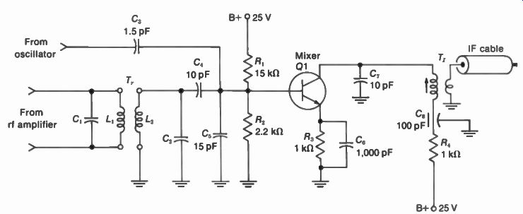
FIGURE 24-16 TRANSISTOR MIXER CIRCUIT
TABLE 24-1 LOCAL OSCILLATOR FREQUENCIES --- For VHF channels, with picture IF carrier of 45.75 MHz in receiver.
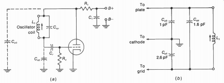
FIGURE 24-17 (a) ULTRAUDION OSCILLATOR AS A MODIFIED COLPITTS CIRCUIT (b)
HOW TUBE CAPACITANCES FORM VOLTAGE DIVIDER FOR FEEDBACK
24-5 The Local Oscillator
The function of the local oscillator is to generate unmodulated sine-wave voltage, or cw output, to beat with the rf signal in the mixer. For each station, the oscillator operates at only the one frequency needed to convert the rf picture and sound signals to the intermediate frequencies of the receiver.
Table 24-1 lists the oscillator frequencies needed for the 12 VHF channels. These values are calculated as 45.75 MHz above the rf picture carrier in each channel, or 41.25 MHz above the rf sound carrier. The same method can be used to calculate the oscillator frequency for each of the UHF channels listed in Appendix A. It is the oscillator frequency that actually tunes in the channel so that it can be converted to the IF band for the receiver.
Triode oscillator circuit. Most common is the ultraudion oscillator, shown in Fig. 24-17a, with a triode tube. This circuit is a modified Colpitts oscillator using the tube capacitances as the voltage divider for feedback. The oscillator coil L1 is connected from plate to grid across Also, Co; and form a capacitive voltage divider across L1 , as shown in Fig. 24-17b. The oscillator voltage across C„,. is the feedback voltage to the grid.
The ultraudion circuit is preferred for the oscillator in television receivers because the stray capacitances are used as part of the tuned circuit. Furthermore, the oscillator coil is not tapped. This feature simplifies switching the coils for every channel.
The oscillator resonant frequency. The output of the oscillator is at the resonant frequency (1,.) of its tuned circuit. Using f,.=1/(2 pi _/LC), we can calculate the resonant frequency in Fig. 24-17. Assume L1 is 0.85 H. The total capacitance across L1 is C„ _p in parallel with the series combination of and C _p,.. For 2.6 pF in series with 1 pF, the combination is 0.7 pF. This value added to the parallel 1.6 pF makes the total C equal to 2.3 pF. With 2.3 pF for C across L of 0.85 H, the resonant frequency f,. is 113 MHz. This is the oscillator frequency for tuning in channel 4 at 66 to 72 MHz. The calculations for the resonant frequency are as follows:
2r'./LC V 0.85 x 10-6 x 2.3 x 10
0.16 x 10⁹ 160 = x10"
• 0.85 x 2.3 1.41 f 113 x 10" = 113 MHz 12
Transistor oscillator circuit. In Fig. 24-18, the NPN transistor Q4 is used as an oscillator. The oscillator coil is across a pair of contacts on the rotary switch S _p shown on channel 13
The arrow on each coil indicates a variable slug for fine tuning.
In the collector circuit of Q4, the 24-V B+ is supplied through R1. The emitter resistor R2 is not bypassed to provide ac feedback. Also, CI4 provides feedback from collector to base. Bias for the base is supplied by R„, through the rf choke from the collector circuit.
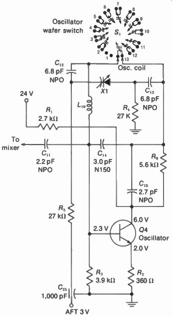
FIGURE 24-18 TRANSISTOR OSCILLATOR CIRCUIT, WITH OSCILLATOR COILS ON WAFER
SWITCH. WAFERS FOR RF AMPLIFIER AND MIXER NOT SHOWN HERE. (FROM ZENITH VHF
TUNER 175-2200-40).
This oscillator has automatic fine tuning (AFT) by means of the varactor or capacitive diode X1. The dc reference voltage of 3 V is supplied from the AFT circuit on a separate board. When the AFT correction voltage changes, the capacitance of X1 varies to change the oscillator frequency.
Capacitors marked NPO have a zero temperature coefficient. The mark N150 means a negative temperature coefficient with the capacitance decreasing by 150 parts per million per degrees Celsius (°C). Switching the oscillator coils. In Fig. 24-18, the wafer switch S, is rotated to connect one oscillator coil for each channel. The switch is on channel 13, but when rotated one step to the right it connects the coil for channel 12. One step to the left is channel 1, or the UHF position. No coil is used here, as the VHF oscillator is not used for UHF operation. S, has the oscillator coils for all 12 VHF channels. However, the coils for the rf amplifier and mixer stages are on separate wafer switches, ganged on a common shaft with S. The oscillator is always on the front section for convenience in adjusting the inductance to set the frequency.
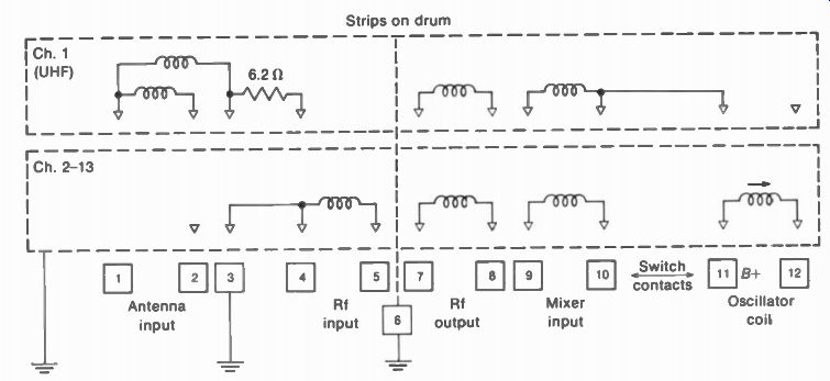
FIGURE 24-19 OSCILLATOR AND RF COILS ON STRIPS FOR TURRET TUNER ONE STRIP
IS USED FOR EACH CHANNEL. (FROM ZENITH VHF TUNER 175-1814).
Connections for the oscillator coils on the strips of a turret tuner are shown in Fig. 24-19.
The coils here are for all the tuner circuits but only one channel. There are 12 strips for all VHF channels plus one strip for the UHF position.
Note that on the UHF strip, B+ voltage is supplied to the rf circuits, which operate for the IF band, but there is no VHF oscillator coil.
Oscillator fine tuning. The oscillator coil is usually constructed with an aluminum screw as the core. The fine tuning control turns the screw in or out. Inductance decreases with an aluminum core because of eddy currents in the metal.
The screw is turned by a gear wheel that is engaged when the fine tuning control is pushed in against its holding spring. The frequency variation is enough to make it possible to tune in a station on the next channel number.
The gear is disengaged when you re lease the fine tuning control. As a result, the adjustment for each channel stays the same when you switch stations. This system is called preset or memory fine tuning.
Set the fine tuning control for the best picture with normal sound. Adjust until you see sound bars in the picture, then back off the control a little. With color, adjust for 920-kHz beat in the picture, then back off for maximum color without the beat.
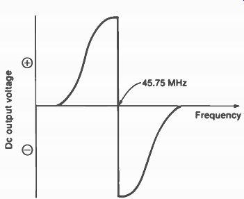
FIGURE 24-20 RESPONSE CURVE OF AFT DISCRIMI NATOR. AMPLITUDE IS 8 V p-p.
24-6 Automatic Fine Tuning (AFT)
The AFT circuit is actually automatic frequency control (AFC) on the local oscillator in the rf tuner. For color receivers, AFT is very useful for tuning in the color without 920-kHz beat. The tuning is generally needed when changing channels, especially with remote control.
The key to AFT operation is having the local oscillator convert the picture carrier to exactly 45.75 MHz in the IF section. This frequency is measured by a discriminator in the AFT circuit, with input from the IF amplifier. The discriminator output is a dc correction voltage that indicates how much off 45.75 MHz the IF carrier frequency is. Since this frequency depends on the oscillator input to the mixer, the AFT voltage indicates the error in oscillator frequency. The AFT circuit can correct a shift in frequency of as little as 50 kHz.
Response curve of AFT discriminator
Two diodes in a balanced detector circuit produce the S response curve shown in Fig. 24-20. The slope is very steep to measure small changes in frequency. The output is zero at balance. For frequency deviations above or below 45.75 MHz, the net dc correction voltage is either positive or negative, depending on whether the frequency is too high or too low.
Correcting the oscillator. This frequency is generally controlled by a varactor for AFT. The varactor is a silicon diode with reverse bias.
Then varying the diode voltage changes the junction capacitance. Typical values may be a C of 10 pF with 10 V reverse bias.
AFT circuit. See Fig. 24-21a. Signal from the IF amplifier on the receiver chassis is coupled by C, and L, to the base of 01. This stage is an IF amplifier for the AFT discriminator using diodes X1 and X2. The collector voltage and base bias for Q1 are provided by the 24-V supply line.
Amplified IF output is coupled from the collector by the discriminator transformer T. The two diodes with T, form a Foster-Seeley or phase-shift discriminator circuit. • T, proportions the signal voltage for X1 and X2 in accordance with the frequency of the IF signal input. Then the rectified output is the error voltage that indicates by how much the IF signal differs from 45.75 MHz.
'See Section 27 for a detailed description of discriminator circuits.
A typical value for the AFT error voltage is 3V. This can be measured with a dc voltmeter at the AFT test point. Actually, the dc output of a balanced discriminator is 0 V on frequency. In Fig. 24-21, though, the dc level of 3 V is inserted from the 24-V supply line, through R„, L2, and R. It should be noted that in some AFT circuits, the IF signal is first rectified by the discriminator. Then the AFT correction voltage is amplified in a dc amplifier. In any case, the dc voltage output of the AFT circuit is connected to the VHF and UHF tuners to correct the oscillator frequency. The AFT circuit is usually on a separate module board or small subchassis.
AFT defeat switch. This is used to turn off the AFT circuit when necessary for manual fine tuning. In Fig. 24-21a, S, grounds the bias line for the base of Q1 to cut off the amplifier. Without IF signal input to the discriminator, there is no rectified output.
AFT action. To check the AFT circuit, turn it off with the defeat switch. Then use the fine tuning control to get a picture with 920-kHz beat.
When the AFT is turned on, the beat should disappear.
AFT alignment. The response curve should look like Fig. 24-20. The main effect on balance is provided by the secondary of the discriminator transformer. The response curve is obtained with an oscilloscope at the AFT test point and IF sweep signal input. The discriminator adjustments are shown in Fig. 24-21b.
It may be possible to readjust the AFT circuit by watching the picture. Turn off the AFT and adjust the manual fine tuning control.
Then turn on the AFT. If the oscillator is de tuned, adjust the secondary of the AFT discriminator transformer for the best picture. When the AFT is turned on and off, there should be no effect on the correct tuning.
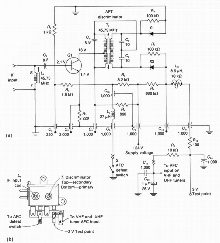
FIGURE 24-21 (a) AFC OR AFT CIRCUIT. R IN OHMS AND C IN PICOFARADS. (b) CONNECTIONS
AND ALIGNMENT ADJUSTMENTS. (FROM ZENITH AFC SUBCHASSIS 150-6)
24-7 Types of RF Tuners
In terms of television channels, the receiver has separate VHF and UHF tuners. Older types of VHF tuners have two tubes, but now transistors are used. The UHF tuner is generally solid state, with just a crystal-diode mixer and transistor for the oscillator stage.
The VHF tuner is usually either the turret type shown in Fig. 24-4 or the rotary-switch type shown in Fig. 24-5. The UHF tuner often uses variable capacitors for continuous tuning through channels 14 to 83. Later types have a detent with 70 click stops, one for each UHF channel (Fig. 24-22). This type uses mechanical stops for the variable capacitor. Instead of varying continuously, the capacitor just moves in little jumps.
All these tuners use mechanical tuning, switching coils or varying a capacitor to tune in each channel. For electronic tuning, varactors are used. Changing the dc voltage on the varactor produces the channel tuning. When the UHF tuner uses varactors, it generally has an rf amplifier stage with the mixer and oscillator.
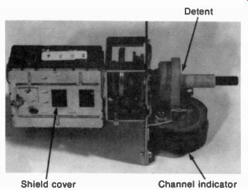
FIGURE 24-22 UHF TUNER WITH DETENT FOR 70 CHAN-NELS. (MAGNAVOX CO.) --- Detent,
Shield cover, Channel indicator
24-8 VHF Tuner Circuits
The complete schematic of a VHF tuner is shown in Fig. 24-23. Q1 is the rf amplifier stage, Q2 the mixer, and Q3 the local oscillator. Rotary wafer switches are used for the station selector.
In the path for antenna signal input, the first components are capristors CPR-1 and CPR-2. A capristor combines a coupling capacitor with a shunt resistor and possibly a spark gap. The capacitor isolates the antenna terminals from the chassis, for 60-Hz ac line voltage, as a safety feature in transformerless receivers.
The shunt resistor discharges any static charge accumulated on the capacitor. A spark gap can also be used across the capacitor as protection against excessive charge on the antenna.
The rf input circuit includes the balun transformer L1 connected to FM and IF traps before coupling the rf signal through C, and Lio to the wafer switch S-4F. Its disk conductor connects this line through C7 to S-3F. From here the signal is connected to the base of the rf amplifier Q1. The base also has forward AGC bias, applied through A.
The amplified rf output is coupled from the collector of Q1 to the base of the mixer Q2, through C,„. The coils on wafer switch S-2F tune the mixer input circuit for each channel. R1 is a damping resistance to provide the required 6-MHz bandwidth on channels 2 to 6. In addition, the coils supply a dc path for collector voltage to Q1, through R4 and R91. The bypass capacitors in this line are C25 and C92. Note that is a feedthrough capacitor, with the double ended terminal indicated by two small circles.
Neutralization of the rf amplifier is provided by the feedback path with L13 and C10.
In the oscillator circuit, the tuning coils are on wafer switch S-1F, connected between collector and base of Q3. The variable inductance L22 is the fine tuning control. L27 is used to tune channels 2 to 6 within range of the fine tuning control, while L28 has the same function for channels 7 to 13. These are called oscillator tracking adjustments.
The oscillator output is injected into the base of the mixer by C18. In the mixer collector circuit, L2, is the IF output transformer. The tap between C27 and C27 in the secondary of L . provides 75-ohm impedance for the cable connected to the IF output jack.
How the switches select the channel. The five wafer switches from right to left in Fig. 24-23 have the following functions:
1. S-1F is the oscillator section. It connects the required inductance for 03.
2. S-2F tunes the mixer input circuit to the selected channel.
3. S-3F operates only on channel 1 for UHF. It tunes the rf circuits to the IF band for the output of the UHF tuner. This jack is at the top of L.
4. S-4F tunes the antenna circuit to the selected channel for input to rf amplifier Q1.
5. S-5 connects 8+ voltage to the UHF tuner only on the channel 1 position of the selector switch.
The wafers have coils for each channel. For the high-band channels, these inductances are just stamped metal loops.
Shorting switches. This means the switch short-circuits all or part of the inductance on a wafer. As an example, S-4F is set on channel 13.
Then the metal disk at the center shorts all the coils on the switch. L,„ tunes the circuit to channel 13, with the stray capacitance in the circuit.
When the switch is moved one position counterclockwise for channel 12, one loop is added to the inductance of L,„ to lower the resonant frequency. The same idea applies for S-2F, with L 2„ tuning the mixer input circuit to channel 13.
Finally, in the oscillator section, L ,„ tunes the circuit for channel 13, and S-1F adds inductance for each of the lower channels. This type of tuner is an incremental-inductance tuner.
Switching to UHF operation. When the station selector is set to the channel 1 position:
S-1F disconnects B+ from the VHF oscillator Q3 so that it does not operate while the UHF oscillator is on.
S-4F disconnects the antenna input circuit from the base of the rf amplifier Q1.
S-3F then connects the channel 1 input jack to the base of Q1. In this path, L _p, C11, and L12 are added for resonance in the IF band. Also, L14 on S-2F is added to the inductance of this section.
S-5 connects the B+ voltage to the oscillator on the UHF tuner.
In summary, then, for UHF operation on charnel 1, the VHF oscillator is disabled, the UHF oscillator is turned on, and the mixer input is tuned to the IF band for the IF output of the UHF tuner.
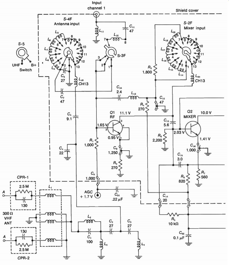
FIGURE 24-23 TRANSISTORIZED CIRCUITS FOR VHF TUNER. R IN OHMS AND C IN PICOFARADS.
(RCA KRK 157A)
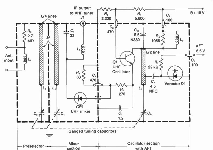
FIGURE 24-24 UHF TUNER WITH GANGED TUNING CAPACITORS R IN OHMS AND C IN pF
(RCA KRK 185)
24-9 UHF Tuner Circuits
In Fig. 24-24, the UHF tuner is divided into three metal compartments, or cavities, as indicated by the heavy lines in the diagram. Each cavity corresponds to a resonant transmission line. The equivalent inductances L 2, L 4, and L M are tuned by C _p C _p and C14. These capacitors are on a common shaft for continuous tuning.
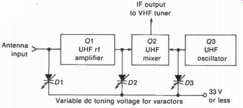
FIGURE 24-25 BLOCK DIAGRAM OF UHF TUNER WITH VARACTOR TUNING. (FROM ADMIRAL
M25 CHASSIS)
The antenna signal input is coupled by L, to the preselector section, which is tuned by C2 to the desired UHF channel. Coupling to the mixer section is provided by a window, marked M for mutual coupling. The mixer input circuit is tuned by C, to the channel frequencies. CR1 is the crystal-diode mixer. Also coupled into the mixer through R2 is output from oscillator Q1, tuned by Cu. The output of the diode mixer is connected to the jack J1 through L,. This IF signal output goes to the VHF tuner, which operates as an IF amplifier on the UHF position.
AFT on UHF tuner. The varactor Q1 in Fig. 24-24 is used to control the oscillator frequency.
Note that Q1 is connected to the oscillator line through C. Since the reverse voltage varies the varactor capacitance, it holds the oscillator at the correct frequency. The nominal value of AFT control voltage, on frequency, is 6.5 V in this circuit. The positive voltage is reverse bias at the cathode of Q1.
UHF varactor tuner. In Fig. 24-25, varactors are used to tune Q1, D2, and Q3, instead of using variable capacitors. Each of the varactors is provided with a dc voltage that tunes the stage to the desired frequency. The dc tuning voltage is determined by the station selector. Different amounts of dc voltage set the tuner for different channels.
Note that the varactor tuner uses an rf amplifier stage for the UHF channels. The extra rf amplification is necessary because varactor tuned circuits have lower Q, compared with a variable air capacitor for the resonant circuit.
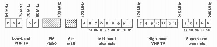
FIGURE 24-26 FREQUENCY ALLOCATIONS OF 24 CHANNELS IN THE VHF SPECTRUM FOR
CABLE TELEVISION.
24-10 Cable Television Channels
Receivers for cable TV require more than 12 channels in the VHF spectrum. Distribution of VHF channels is preferred because cable losses are much greater in the UHF band. In order to provide additional VHF channels for a wide-band, single-cable system, the frequency allocations shown in Fig. 24-26 are used. In addition to the 12 standard FCC channels for broadcasting, there are 14 cable channels. A cable channel has the 6-MHz bandwidth of an FCC channel but is used only for CATV. It should be noted that EIA recommendations are to add six more cable channels for a total of 20. Mid-band cable channels. These include nine channels from 120 to 174 MHz. The channels have the letters A to I, or are numbered 84 to 91 starting with channel B. The band of 120 to 174 Mhz is not used for television broadcasting in order to prevent interference with other radio services. However, the signals for cable TV are not broadcast by radiation.
Super-band cable channels. These include five channels from 216 to 246 MHz, just above FCC channel 13. The super-band cable channels have the letters J to N or are numbered 92 to 96.
CATV converter. This unit is essentially an rf tuner for the mid-band and super-band cable channels. The circuit is usually a double super heterodyne, with two local oscillators. One frequency conversion is done to raise the rf signal frequencies. This method reduces the ratio of highest to lowest frequencies for easier tuning over both bands. However, the second frequency conversion produces the standard IF signals at 45.75 MHz and 41.25 MHz for the receiver. When the cable converter is used with VHF and UHF tuners, they all feed IF signal to an IF amplifier on the converter, which has the IF cable to the main chassis. Another method is to convert all cable channels to channel 12 for the VHF tuner, or to any channel not used in the area.
24-11 Varactors for Electronic Tuning
The varactor is a silicon diode that serves as a voltage-variable capacitance. An increase in reverse bias makes the capacitance decrease.
The varactor is also called a varicap or capacitive diode. Its schematic symbol shows a semi conductor diode with a variable capacitor.
In addition to its function in correcting the oscillator frequency in an AFT circuit, the varactor can be used to tune in the desired channel.
This method is considered electronic tuning because mechanical rotation of a switch or turret is not necessary. The varactors for each stage are tuned by applying the required dc tuning voltages.
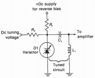
FIGURE 24-27 A BASIC CIRCUIT FOR VARACTOR TUNING.
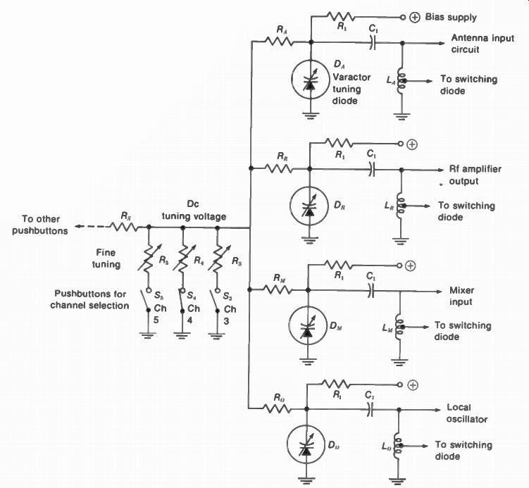
FIGURE 24-28 CIRCUIT WITH FOUR VARACTORS TO CHANGE CHANNELS BY TUNING RF
AMPLIFIER, MIXER, AND OSCILLATOR ON TUNER.
Varactor-tuned circuit. Figure 24-27 illustrates how the varactor 01 is used in a resonant circuit.
L, provides the required inductance, while D1 is the voltage-variable capacitance. The coupling capacitor C, has little reactance at the resonant frequency but is needed to prevent the dc supply voltage from shorting to ground through L. The dc voltage supplied through R, provides the reverse bias for Q1. This voltage is positive at the N cathode of the diode.
Without any other voltage, the tuned circuit is resonant at a particular frequency. however, the dc tuning voltage supplied through R„, varies the reverse voltage on D1. Then its capacitance changes to vary the resonant frequency. As a result, the varactor makes it possible to tune the resonant circuit by varying the amount of reverse bias for Q1. Typical values are 20 pF with 4-V reverse bias. The C decreases with more reverse voltage.
Varactor tuning for channel selection. See Fig. 24-28. The four circuits tuned by the varactors are the local oscillator, mixer input, and rf amplifier input and output. Each circuit with a varactor diode and inductance L, corresponds to the varactor-tuned circuit in Fig. 24-27. As a result, the four varactors provide tuning for all the resonant circuits on the tuner. The rf circuits are tuned to the channel frequencies, while the oscillator is above the rf signal.
The question of which channel is tuned in depends on the value of the dc control voltage connected to the varactors. One common line is used for the tuning voltage, with a dc voltage divider for each channel.
Pushbuttons are generally used to switch in the channel-tuning voltage. As an example, in Fig. 24-28 the pushbutton is in for channel 4.
Then R, forms a voltage divider with Rs to supply the amount of dc voltage needed to tune the varactors for this channel. The fine tuning control R, can be varied to make slight changes in the dc tuning voltage. Note that in this case the fine tuning affects all the stages on the tuner, not just the oscillator.
Only three channels are illustrated in Fig. 24-28, but the same idea applies to all channels.
The desired channel is selected by its pushbutton, which supplies the required dc tuning voltage. Furthermore, although channel selection is shown here for a VHF tuner, similar circuits are used for the UHF tuner.
Switching diodes. The VHF channels 2 to 13 include frequencies between 54 and 216 MHz.
This range has a ratio of 4:1, which is too much of a variation for capacitive tuning. Therefore, part of the inductance is shorted to reduce L for the high-band VHF channels. A switching diode has the function of shorting a tap on the coil when the selector switch is set for a channel from 7 to 13.
In Fig. 24-29, D1 is the switching diode connected through C, to a tap on the tuned-circuit inductance L. When D1 is not conducting, it is an open circuit without any effect on the coil. However, when positive voltage is applied to the D1 anode, it conducts. Then its low resistance is equivalent to a short circuit across the bottom section of L. The blocking capacitor C, is needed to prevent the diode voltage from shorting to ground through the coil.
Whether the switching diode conducts or not is decided by the band-switching voltage supplied through S. When this switch is open, no voltage is applied to 01 and it is an open circuit. All the turns in L, are used, then, for the low-band VHF channels 2 to 6. However, when S, is closed, a positive voltage is applied to the D1 anode to turn on the switching diode. Then only some of the turns on L, are used for the high-band VHF channels 7 to 13.
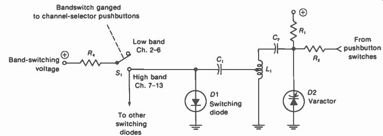
FIGURE 24-29
FUNCTION OF THE SWITCHING DIODE IN CHANGING BANDS FOR VARAC-TOR TUNING.
Only one switching diode is shown in Fig. 24-29. However, each of the tuned circuits for all the stages has a switching diode connected to a tap on the coil. The positive band-switching voltage is applied to all the switching diodes.
Note that the bandswitch S, is ganged with the channel selector to apply switching voltage for the pushbuttons 7 to 13. In addition to the switching voltage for channels 7 to 13, re member that the pushbuttons apply tuning voltage to the varactors for selecting each of the channels.
24-12 RF Alignment
The exact procedure for aligning the rf tuner is given in the manufacturer's service notes, but the main requirements are as follows:
1. The rf tuned circuits for antenna input, rf amplifier output, and mixer input must be tuned to the 6-MHz band of the selected channel. See the typical rf response curve in Fig. 24-14.
2. The local oscillator must be set to the correct frequency for tuning in each channel.
When aligning the rf tuned circuits, the tuner should have its normal AGC bias. When the oscillator frequency is adjusted, the AFT circuit is off, but the average dc correction voltage must be present at the AFT terminal. The shield cover must be on because its capacitance affects all the tuner adjustments.
Realignment of the rf signal circuits is seldom necessary. However, the oscillator will need frequency adjustments if this tube or transistor is replaced.
Oscillator adjustments. In some receivers, the oscillator adjustment screws are separate from the fine tuning control, which is a variable capacitance. In this case, set the oscillator on each channel for the best picture with normal sound. The fine tuning control should be at mid position. The best picture is obtained by adjusting for sound bars and then backing off a little.
In turret tuners with separate strips for each channel, the order of oscillator adjustments does not matter. One channel can be adjusted without affecting the others. In wafer switch tuners, though, the oscillator inductance is usually a series of coils. The frequency is reduced for lower channels by adding more turns for the oscillator coil. Then channel 13 must be adjusted first when aligning the oscillator coils. The adjustment for any one channel affects all the lower channels. However, some switch tuners have separate oscillator coils for each channel.
In cases where no broadcast station is available to supply a picture on the channel, or if the diner is not connected to the receiver to check its IF output, the oscillator frequency can be measured directly. The required oscillator frequencies for the VHF channels are given in Table 24-1, with all the channels listed in Appendix A. One method is to heterodyne the oscillator output against a crystal-calibrated oscillator for zero beat. The marker-generator in Fig. 24-30 has its own audio section so that you can hear the low-frequency beat down to a null at zero beat. This signal generator also can supply marker frequencies for the rf response curve.
Rf alignment. Using a sweep generator and oscilloscope to obtain the rf response curve is similar to the method for IF alignment. However, the sweep generator is connected to the antenna input terminals. The generator must be set to the same channel as the receiver, generally channel 10. It is usually not necessary to align the rf circuits on every channel. A typical sweep generator for IF and rf alignment is shown in Fig. 23-22. The oscilloscope is connected to the mixer output, usually at a test point on the top of the tuner.
The tuned circuits aligned for the rf response curve are the antenna input circuit to the rf amplifier, its output circuit, and the input to the mixer. In the mixer output, its IF circuit is part of the IF alignment, not the rf response.
Specific instructions for rf alignment are given in the manufacturer's service notes. Actually, repair or alignment is generally done by ser vice companies that specialize in rf tuners.
This service is also provided for alignment of solid-state IF modules. The tuner or IF module usually can be removed easily from the main chassis.
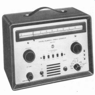
FIGURE 24-30 CRYSTAL-CALIBRATED SIGNAL GENERATOR. (RCA)
UHF alignment. A variable air capacitor used in UHF tuners usually has segments on the rotor blade, as shown in Fig. 24-31. These can be adjusted for the rf signal circuits and the oscillator. It should be noted, though, that some UHF tuners are factory-sealed because they are not to be aligned in the field.
24-13 Remote Tuning
Many receivers have provision for remote operation. The basic functions include changing channels, varying the volume, and turning the set on and off. The ultrasonic system in Fig. 24-32 is generally used. A small hand-held remote transmitter, or "clicker," radiates sound waves at frequencies around 40 kHz. These frequencies are too high for the human ear to hear, but the waves of compression and rarefaction through the air operate the microphone at the receiver.
The microphone is a transducer that converts the sound waves to electric signals. The remote-control amplifier is an additional chassis in the receiver cabinet for operation from the remote transmitter. Amplification and rectification of the remote signals are necessary to obtain enough dc control voltage for each function.
Sound waves are used for the remote transmitter, in preference to radio transmission, in order to minimize interference problems. It should be noted that sound waves do not pass easily through the walls of a room. The remote transmitter can operate the control unit from a distance of up to 20 to 30 ft.
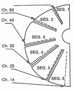
FIGURE 24-31 SEGMENTS ON ROTOR BLADE OF EACH CAPACITOR IN UHF TUNER. (RCA
KRK 152)
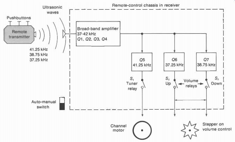
FIGURE 24-32 REMOTE CONTROL FOR THREE RECEIVER FUNCTIONS
Control frequencies and functions. There are no standard values, but the frequencies in Fig. 24-32 are typical. The main functions are:
41.25 kHz 37.25 kHz 38.75 kHz
Turn channel selector
Volume up / Volume down and turn set off
In this example, the channel selector is rotated in only one direction. To turn it both ways, an additional control frequency can be used. More functions that may be used, with typical frequencies, are:
43.25 kHz
40.25 kHz
44.75 kHz
35.75 kHz
Chroma gain up
Chroma gain down
Tint toward purple
Tint toward green
However, channel selection and volume control are most common for remote operation because they do not have automatic control circuits in the receiver. Remote contrast and brightness controls are usually not included because the AGC circuit automatically controls the receiver gain.
For remote operation, the channel selector is turned one position by a motor on the shaft of the tuner. A relay in the remote-control unit turns on the tuner motor. The volume control can have a small step motor that turns the shaft.
For chroma gain, a dc control voltage can supply AGC bias to the chroma bandpass amplifier to vary the color level. For tint control, the phase angle of demodulation can be shifted toward either purple or green.
Channel programming. Unused channels can be skipped by pin settings on an index wheel that turns with the tuner shaft. The channel motor stops when its ground return is opened. If the index pin is turned so that it does not open the ground connection, the motor keeps moving to the next channel until it is stopped by an open ground return.
Transmitter unit. This may be either an electronic oscillator or a mechanical source of vibrating sound waves. Figure 24-33 shows a mechanical unit, often called a "bonger." A separate metal rod, similar to a tuning fork, is used for each frequency. When the control but ton is pushed, a spring-loaded hammer strikes the rod and it radiates sound through an open grille at the top. No battery is needed for this transmitter, as its operation is entirely mechanical.
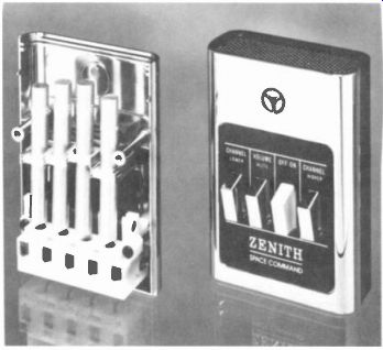
FIGURE 24-33 MECHANICAL TYPE OF TRANSMITTER UNIT FOR REMOTE CONTROL. (ZENITH
RADIO CORP.)
The electronic unit contains transistorized oscillator circuits. Operating frequencies are also around 40 kHz, the same as a mechanical unit. When each control button is pushed, it connects a capacitor to change the oscillator frequency. The oscillator drives a ceramic transducer serving as a loudspeaker to produce ultrasonic output. A small battery is the power supply for the transistor. This type transmits the remote signal as long as the control button is held down.
Control chassis. This unit is a small separate subchassis. Referring to Fig. 24-32, the output of the microphone is amplified in a high-gain, broad-band amplifier with four transistors. The amplified output is then fed to a parallel bank of driver stages tuned to the control frequency for each function.
Normally, the output stage is cut off. With enough signal input, though, it is driven into conduction to operate the relay in its output circuit. The auto-manual switch applies power to the remote-control chassis at all times, so that the receiver can be turned on by remote operation.
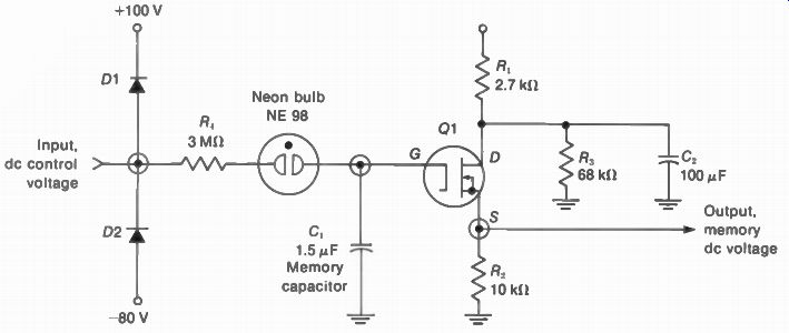
FIGURE 24-34 MEMORY CIRCUIT USED FOR REMOTE SYSTEMS WITH ELECTRONIC CONTROL
(MOTOROLA INC.)
Memory circuit. In some receivers, dc voltage control may be used instead of a motor for remote operation. An example is a varactor tuner that does not have a rotating switch. For dc voltage control, some method of remembering the desired condition is needed. Otherwise, removal of the control signal would allow the circuit to return to its original condition. Therefore, a memory circuit is used to hold the effect of the control voltage in remote operation.
The module in Fig. 24-34 can hold the control voltage by storing charge in the memory capacitor C,. A positive or negative voltage in the input makes D1 or D2 conduct. The input is dc control voltage from the remote-control chassis. When either diode is on, the neon bulb is ionized. The bulb is then a low resistance, allowing C, to be charged.
Positive input at the anode makes D1 con duct. Then the + 100-V supply charges C, positive. Negative input at the cathode of D2 allows it to conduct to charge C, negative from the supply of -80 V. The neon bulb is ionized from the supply voltage of +100 V or -80 V when either D1 or D2 conducts. After the control-voltage input is removed, the diodes cannot conduct and the neon bulb de-ionizes to become an open circuit. however, the memory capacitor C, has become charged to store the effect of the control voltage.
The voltage across C, at the gate of Q1 determines how much the FET conducts. For output, R, in the source circuit produces dc control voltage that depends on the amount of transistor current. The R2 voltage is proportional to the amount of input control voltage, therefore, but the output remains the same as long as C, holds its charge.
24-14 Tuner Troubles
The three most common problems here are:
1. Mechanical troubles, including dirty switch contacts or a weak detent spring
2. Snow in the picture, although the contrast may be good
3. No picture and no sound, but a normal raster
One way to determine if the tuner is defective is to substitute a good one. Commercial "tuner subber" units such as the one in Fig. 24-35 are available. This is a battery-operated transistor tuner. To substitute tuners, you just switch the IF cable from the tuner in the receiver.
Dirty switch contacts. Typical symptoms are: (1) the channel switch must be rocked to get the picture, (2) there is only picture, no sound, or vice versa, on some channels, or (3) one or two channels cannot be received at all. The dirty contacts are caused by tarnishing of the silver plating.
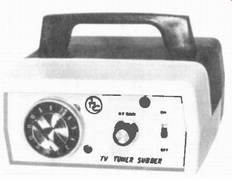
FIGURE 24-35 -- PORTABLE TUNER SUBSTITUTE FOR TELEVISION RECEIVERS (CASTLE TV
TUNER SERVICE INC.)
The contacts can be cleaned and lubricated by commercial sprays especially made for tuners. Just spray all the contacts and rotate the switch in both directions. This cleaning job usually lasts a year or two. In extreme cases of dirty contacts, a turret can be taken out of its metal case by removing a spring clip. Then the fixed switch contacts on the housing can be cleaned thoroughly. The eraser end of a pencil can be used to remove the dark coating down to the shiny silver base.
Snow in the picture. The snow on the screen is the visible effect of shot-effect noise generated in the mixer stage. Therefore, the snow can be used as an indicator to locate troubles in either the rf circuits before the mixer or the IF section after the mixer.
Suppose the trouble is no picture and no sound, or weak picture. Turn up contrast and volume controls to maximum. Note whether there is an increase in snow and the hissing sound of receiver noise. This effect indicates that the mixer stage is operating and all the following stages are amplifying the noise from the mixer. Either the signal from the antenna is too weak or the rf amplifier does not have enough gain.
SUMMARY
1. VHF tuners for channels 2 to 13 are generally the turret or switch type. This is a separate subchassis with rf amplifier, mixer, and oscillator stages. Ganged tuning is provided by the station selector. The fine tuning control varies the local oscillator frequency.
2. UHF tuners use variable-capacitor tuning for channels 14 to 83. Later models have a 70-position detent. The IF output of the UHF mixer is amplified by the VHF tuner on UHF operation.
3. For electronic tuning, capcitive-diode varactors are used for selecting the desired channel. The capacitance is varied by a dc tuning voltage.
4. The varactor is also used for automatic fine tuning (AFT) on the local oscillator.
This circuit holds the oscillator at the correct frequency for the best picture without interference from the sound signal.
5. The rf-amplifier must have low noise for a high signal-to-noise ratio in the amplified rf signal to the mixer.
6. The input impedance of the tuner is generally 300 ohm at the antenna terminals for twin lead or 75 ohm at a jack for coaxial cable.
7. The mixer stage requires rf signal input and oscillator injection voltage to produce the IF output.
8. The local oscillator generally uses a modified Colpitts circuit called the ultraudion. This circuit features one LC tuned circuit with a voltage divider formed by capacitances in the tube or transistor. The local oscillator tunes in the desired station, as the oscillator frequency determines which channel can be converted to IF signal.
9. For oscillator alignment, adjust each coil for best picture, without sound bars and with no 920-kHz beat in color receivers.
10. The rf amplifier can be aligned by the visual response-curve method, usually on channel 10, for a symmetrical curve with 6-MHz bandwidth.
11. Cable television uses special CATV channels, illustrated in Fig. 24-26.
12. Wireless remote control of the receiver is generally done with the ultrasonic system shown in Fig. 24-32. The operating frequencies are around 40 kHz.
13. Two common mechanical troubles in tuners are a weak detent spring and dirty switch contacts. In both cases, the station-selector setting is too critical when tuning in a channel.
14. Snow in the picture is the effect of receiver noise. Most of the noise is produced in the mixer stage. The rf amplifier is the most important stage in providing a high signal-to-noise ratio for the signal input to the mixer for minimum snow.
Self-Examination (Answers at back of guide)
1. The fine tuning control varies the frequency of the: (a) rf amplifier; (b) mixer input circuit; (c) antenna input circuit; (d) local oscillator.
2. With an IF picture carrier frequency of 45.75 MHz, to tune in channel 13 the local oscillator frequency is: (a) 211.25 MHz; (b) 215.75 MHz; (c) 257 MHz; (d) 302.75 MHz.
3. An oscillator circuit tuned to 160 MHz has an L of 1 µH. If this is increased to 4 µH, the new resonant frequency will be: (a) 80 MHz; (b) 160 MHz; (c) 320 MHz; (d) 400 MHz.
4. The oscillator frequency is set for: (a) maximum sound; (b) minimum sound; (c) sound in the picture; (d) best picture.
5. A varactor is used as a voltage-controlled: (a) capacitor; (b) inductance; (c) resistance; (d) amplifier.
6. The AFT discriminator is tuned to: (a) 41.25 MHz; (b) 45.75 MHz; (c) 113 MHz; (d) 3.58 MHz.
7. A typical frequency in a remote control system is: (a) 40.25 kHz; (b) 45.75 MHz; (c) 10.7 MHz; (d) 54 MHz.
8. Which of the following replacements may require oscillator realignment: (a) rf amplifier; (b) first IF stage; (c) antenna; (d) oscillator stage.
9. Which of the following can cause excessive snow in the picture: (a) excessive antenna signal; (b) weak rf amplifier; (c) weak video amplifier; (d) excessive oscillator injection voltage.
10. Which of the following stages usually has AGC bias: (a) local oscillator; (b) mixer; (c) rf amplifier; (d) AFT discriminator.
11. In electronic tuning with varactors, a switching diode has the function of: (a) switching channels; (b) shorting a tap on L in the tuned circuit; (c) shorting the AFT voltage; (d) switching to UHF operation.
12. For the VHF tuner during UHF operation, which of the following is not true: (a) the VHF oscillator is off; (b) the mixer is tuned to the IF band; (c) B+ voltage is supplied to the UHF tuner; (d) the mixer stage is cut off.
Essay Questions
1. Give the function of each of the three stages in a VHF tuner.
2. What is the function of the station selector? The fine tuning control?
3. Give the input and output signals for the VHF mixer stage. Which is the next stage for the mixer output?
4. Give the input and output signals for the UHF mixer stage. Which is the next stage for the mixer output?
5. Draw the desired rf response curve for channel 10, marking the sound and picture carrier frequencies with the color subcarrier.
6. Draw a block diagram of equipment and connections for obtaining a visual response curve for the rf section.
7. Compare two characteristics for a triode tube, an NPN transistor, and an FET in an rf amplifier circuit.
8. Give three requirements of the rf amplifier stage.
9. Why is neutralization used with triode rf amplifiers?
10. Define the following: balun, feedthrough capacitor, capristor, and detent spring.
11. Referring to the block diagram of a combination VHF-UHF tuner in Fig. 24-2, give the operating frequencies for tuning in channel 7. Do the same for channel 21.
12. Describe the effect on picture, sound, and color when the oscillator frequency is varied to cause: (a) sound carrier too high on IF response curve; (b) picture carrier too high on IF response curve.
13. Why is AFT more important in color receivers than in monochrome? 14. Give two features of a varactor diode. Give two uses for varactor diodes in rf tuners.
15. Give the function of the AFT-defeat switch.
16. Describe briefly how to check whether the AFT circuit is operating normally.
17. What is the reason for using switching diodes in circuits for electronic tuning? 18. Give two differences between ultrasonic waves at 40 kHz and rf signal at the same frequency.
19. Give the function of the following in a remote-control system: transmitter unit, microphone, control chassis; auto-manual switch, and channel-control relay.
20. Name two types of transmitter units for remote operation.
21. What is meant by programming, in remote operation of the channel selector?
22. When is a memory circuit needed in a remote-control system?
23. What is meant by the mid-band and super-band channels for cable television? 24. For a receiver with memory fine tuning, how would you align the oscillator after the tube is changed?
25. Why is minimum noise more important in the rf amplifier than in the last IF stage?
26. For each of the following, state what you think is wrong and why. (a) No picture and no sound for channel 5 only on a turret tuner; (b) channel 11 is received on the channel 10 position; (c) no picture and no sound on all channels, but a clean raster without snow; (d) no picture and no sound on all channels; the picture is very snowy when the contrast is turned up; (e) good contrast but snow in the picture on all channels; (f) good contrast but snow in the picture only on some channels; (g) the picture is weak with no color on some channels, but becomes perfect when the channel-selector switch is moved slightly.
27. Referring to Fig. 24-23, give the effect of the following troubles: (a) R,„ for the emitter of Q3 is open; (b) L 2 „ for the collector of Q1 is open; (c) R5 for the base of Q2 is open; (d) R _p in the B+ line is open.
28. Referring to Fig. 24-28, give the function of R _p C _p L„, and D„ for the oscillator stage.
29. Describe briefly two mechanical troubles in tuners.
30. Why is the problem of snow in the picture associated with the antenna signal input and the rf amplifier?
Problems (Answers at back of guide)
1. Calculate the lowest and highest frequencies for a VHF oscillator to tune in channels 2 to 13. Do the same for UHF channels 14 to 83.
2. What oscillator frequency is needed to tune in channel 3? Calculate the L needed with 5-pF C for resonance at this frequency.
3. Calculate the wavelength of an ultrasonic signal at 4C kHz if the velocity of sound waves is 1,130 ft/s.
4. Calculate the capacitive reactance of the 130-pF capristor used in Fig. 24-23 for the frequencies of 60 Hz and 60 MHz.