An antenna or aerial can be simply a length of wire or any conductor which has current induced in it by the transmitted electromagnetic wave. To have enough signal, though, the antenna should either be very long or have a resonant length that magnifies the effect of particular frequencies. The resonance effect for the length is related to the frequency and wavelength of the signal current in the conductor.
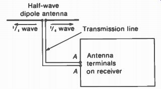
For the VHF and UHF television channels, one-half wavelength is a practical size, one which ranges from approximately 8.5 ft for the lowest frequency to 0.5 ft for the highest frequency. Therefore, the basic antenna for television is the half-wave resonant dipole illustrated in Fig. 25-1. The dipole intercepts the radiated electromagnetic wave to provide induced signal current in the antenna conductors. The transmission line conducts the signal current to the antenna input terminals of the receiver. It should be noted that the antenna signal includes both the picture and sound carrier signals, which are received by the same antenna. Also, a combination antenna with multiple dipole elements can receive all the television channels.
The receiver needs a good antenna signal to reproduce a good picture. A1 though most receivers can produce sufficient contrast with weak antenna signal, the antenna and transmission line determine the important features of no snow and no ghosts. The required amount of antenna signal is about 100 to 2,000 V. Cable distribution systems are designed for 1,000 µV, or 1 mV, antenna signal at the receiver.
It should be noted that the antenna requirements are essentially the same for color and monochrome television. After all, the color signal is only a side band of the picture carrier signal in the standard 6-MHz channel. The only difference is that poor antenna signal is more obvious in a color picture. In fact, there may be no color if the antenna response does not have the bandwidth to include the color frequencies.
More details of antennas and transmission lines are described in the following topics:
25-1 Resonant length of an antenna
25-2 Definition of antenna terms
25-3 How multipath antenna signals produce ghosts
25-4 Straight dipole
25-5 Folded dipole
25-6 Broad-band dipoles
25-7 Long-wire antennas
25-8 Parasitic arrays
25-9 Multiband antennas
25-10 Stacked arrays
25-11 Transmission lines
25-12 Characteristic impedance
25-13 Transmission-line sections as resonant circuits
25-14 Impedance matching
25-15 Antenna installation
25-16 Multiple installations
25-17 Troubles in the antenna system
25-1 Resonant Length of an Antenna
The wavelength and frequency of the radiated electromagnetic wave are inversely proportional. The higher the frequency, the shorter the corresponding wavelength. In addition, the wavelength depends on the velocity of propagation, which is the speed of light for radio waves in free space. Specifically, velocity 3 x 10" cm/s A - frequency 186,000 mi/s^-1 (25-1)
... where lambda (A) is wavelength and f is frequency in Hz.
When the physical length of the antenna, in feet or meters, is cut to equal either one-half or one-quarter of the wavelength corresponding to the signal frequency, the antenna is resonant at that frequency. The result is a resonant rise in antenna current. Multiples of these lengths are considered harmonic resonances. The reason why an antenna can be considered resonant is that the length determines how long it takes for current to flow to the open end.
The two basic types of resonant antennas are the grounded quarter-wave Marconi antenna used at lower frequencies and the half-wave Hertz antenna in Fig. 25-1. The half-wave antenna usually consists of two quarter-wave elements insulated from each other, which add to provide a half wavelength. This is called a dipole. The dipole antenna operates independently of ground and therefore may be installed far above the earth or other absorbing bodies.
Because of this, and because the physical length of a half wave is a practical size at high frequencies, the dipole is the basic antenna in television.
FIGURE 25-1 ANTENNA AND TRANSMISSION LINE CONNECTED TO RECEIVER
More elaborate antenna arrays are usually just combinations of dipoles.
On the basis of Eq. (25-1), the formula for the length of a half wave in feet is derived as L = 492/f, where f is in MHz and L gives the half wavelength in feet, in terms of the electromagnetic field traveling with the speed of light.
However, the resonant length of a half-wave conductor is slightly less than a half wave in free space because the antenna has capacitance that alters the current distribution at the ends of the antenna. This end effect requires foreshortening of the conductor length, to provide the resonant current distribution that corresponds to the length of a half wave in free space. Wider antenna conductors and higher frequencies require more foreshortening, but it can be taken as approximately 6 percent for the antennas used in television. Therefore, the length of the half-wave dipole is computed from the formula
462 L(ft) = f(MHz) (25-2)
L gives the length of the half-wave dipole directly in feet. This is the actual physical length of the half-wave antenna corresponding to an electrical half wave. As shown in Fig. 25-1, one half this value is used for the length of each of the two quarter-wave poles. The small insulation distance between the two poles can be considered negligible. For a dipole tuned to 60 MHz, as an example, the length of the half wave is 7.7 ft, and each section is made 3.85 ft long.
25-2 Definition of Antenna Terms
Wave polarization. The moving, electromagnetic field, which is the radio signal, consists of two components: a magnetic field associated with the current in the transmitting antenna and the electric field associated with its potential.
The two fields are perpendicular to each other in space, and both are perpendicular to the direction of travel of the wave. When the electro magnetic wave passes the receiving antenna, it induces antenna current with the same variations as the transmitted radio signal.
The polarization is arbitrarily defined as the direction of the electric field. This is determined by the physical position of the antenna in space. A horizontal dipole is horizontally polarized. Then the magnetic lines of force are in the vertical plane around the conductors and the electric field is horizontal between the conductors. An antenna vertical with respect to earth is vertically polarized. Horizontal polarization is specified by the FCC for transmission in the tele vision and FM broadcast bands. Therefore, the receiving antenna is mounted horizontally for maximum pickup of a horizontally polarized wave. Horizontal polarization is chosen because experimental results show more signal strength and less reflection for frequencies in the VHF and UHF spectrum. Also, the horizontal directivity of the receiver dipole helps reduce ghosts.
Microvolts per meter. This unit is a measure of field strength. A meter is slightly less than 40 in.
As an example, when a resonant half-wave dipole 1 m long provides 300 µV signal to the transmission line, the field strength is 300 µV/m.
The antenna height is standardized, often at 30 ft, and the antenna polarization is the same as the wave polarization.
Note that the same field strength produces more antenna signal in a longer antenna, which is resonant for lower frequencies. As an example, assume a field strength of 800 µV/m with a half-wave dipole 4.62 ft long for resonance at 100 MHz. The antenna signal then is 1,120 µV, because the length is 1.4 times more than a meter. A half-wave dipole 2.31 ft long for resonance at 200 MHz in the same field provides one-half the antenna signal, equal to 560 µV, since this antenna has one-half the length.
The field strength of the rf carrier signal at the receiver antenna depends on radiated power and propagation characteristics for the carrier frequency. Even though several stations may transmit from one location, the field strength at the receiver is generally not the same for different channels. In addition, the characteristics
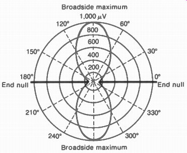
FIGURE 25-2 POLAR DIRECTIVITY PATTERN IN HORIZON TAL PLANE FOR HALF-WAVE
DIPOLE ANTENNA.
Broadside maximum of the receiver antenna vary for different frequencies.
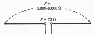
FIGURE 25-3 IMPEDANCE OF HALF-WAVE DIPOLE ANTENNA.
Polar directivity patterns. As shown in Fig. 25-2, signal strength is plotted in polar coordinates to show magnitude and direction. The angle gives the direction for which the signal strength is plotted, while the length of the radial arm defines the magnitude. The polar diagram shows the horizontal directivity pattern of the antenna, as determined by the current distribution of the antenna conductor. For a transmitting antenna, the pattern shows in which direction the antenna radiates the most signal; for a receiving antenna the pattern shows the direction from which most signal is intercepted by the antenna conductor. Rotating the antenna for the direction of best signal pickup is called orientation.
A half-wave dipole at its fundamental resonant frequency has the figure-eight directivity pattern in Fig. 25-2. The antenna receives best from the front and back, broadside to the antenna conductor, with little signal received from directions off the ends. As examples, in Fig. 25-2 the antenna provides 1,000 µV for signal in the broadside direction, about 500 µV signal at 60 deg, and a null of practically zero signal at 0 deg and 180 deg. This pattern applies only for half-wave resonance. For frequencies off resonance, the directional pattern changes because of a different current distribution on the antenna.
Antenna impedance. This impedance Z„ varies with the values of current at different points along the antenna. For a resonant half-wave dipole, Z„ is approximately 72 ohm at the center, as shown in Fig. 25-3. At the ends, Za is several thousand ohms. Intermediate points have intermediate values. Furthermore, the value of Zn at the center is higher than 72 ohm for frequencies off resonance. These values are ac impedances corresponding to an E/I ratio, which cannot be measured with an ohmmeter.
Antenna bandwidth. The half-wave antenna is equivalent to a resonant circuit with resistance and reactance. Therefore, the antenna can be considered as having a value of Q, which deter mines its bandwidth. Larger diameter for the antenna conductors decreases the reactance, allowing lower Q and wider frequency response.
For this reason, metal tubing of 1/4 to 1/2 in. diameter is used for the receiving antenna.
Antenna gain. This is a term used to express the increase in signal for one antenna over a standard antenna, usually a half-wave dipole having the same polarization. Antenna gain is generally used in connection with directional antenna systems with multiple elements and is measured in the optimum direction. The gain is usually stated in decibels. An antenna with a gain of 3 dB, as an example, has a power gain of 2 or a voltage gain of 1.4. Double the voltage is a gain of 6 dB. Typical curves for gain are shown in Fig. 25-17b for a VHF antenna and Fig. 25-22b for a UHF antenna.
Front-to-back ratio. This indicates the amount of signal the antenna receives from the front compared with signal received from the back.
As an example, if the antenna intercepts 1,000 µV of signal from a transmitter in front, but only 500 µV for signal of the same frequency arriving from the back, the front-to-back ratio is 2 times in voltage, or 6 dB. Summary of desirable antenna characteristics. Multiple dipole elements can provide many types of combinations. In general, more dipoles intercept more signal, but the antenna characteristics determine how much useful signal is delivered by the transmission line to the receiver. The antenna should have high gain to provide enough signal for a good signal-to noise ratio, especially in fringe areas. However, high gain is generally associated with narrow bandwidth, which may limit reception to one channel. An antenna impedance of 72 to 300 is desirable for matching to transmission line.
Very important is a good front-to-back ratio to prevent ghosts in the picture caused by receiving the same signal from two different directions. In addition, a narrow forward lobe for the antenna directivity pattern helps reduce ghosts.
Such an antenna with a sharp directional pattern generally has high gain and narrow bandwidth.
FIGURE 25-4 GHOST CAUSED BY REFLECTED SIGNAL.
25-3 How Multipath Antenna Signals Produce Ghosts
As shown in Fig. 25-4, a ghost is a duplicate image, a little to the side of the original. Usually, ghosts are caused by multiple antenna signals from the same station which are received over paths of different lengths. Referring to Fig. 25-5, the receiving antenna at point C receives signal from the transmitting antenna at A by two separate paths. The path ABC for signal reflected from the building at B has a length of 6 + 3 = 9 mi. The direct path AC is 7 mi. Thus the path for reflected signal is 2 mi longer in this example.
Since the velocity of the radiated signal is 186,000 mi/s and the extra length is 2 mi, the reflected wave is delayed by 2/186,000 s at the receiving antenna, compared with the direct wave. This time delay is approximately 11 Ms.
The electron beam scanning the screen of the picture tube requires about 55 As to scan across one horizontal line. On a picture having a width of 20 in., then, it requires only 5.5 u-s to scan 2 in. The reflected signal, delayed in reception by 11 is, will produce a second image displaced from the original by 4 in. The ghost is displaced to the right, in the direction of scanning, because the reflected signal arrives at the receiving antenna later in time than the direct signal. Any conducting material can produce reflection, as induced current in the conductor reradiates the signal. However, a nonconductor does not produce reflections.
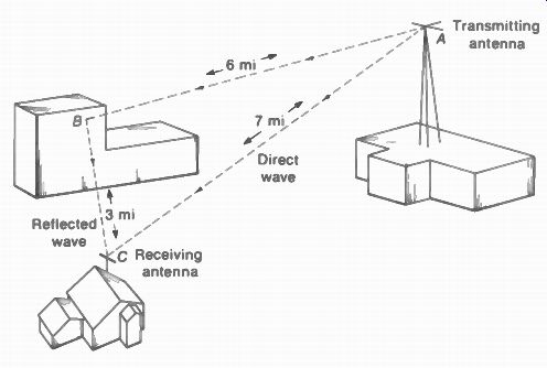
FIGURE 25-5 RECEPTION OF MULTIPATH SIGNALS. THE DISTANCE ABC FOR THE REFLECTED
SIGNAL IS 2 MI LONGER THAN THE PATH AC FOR DIRECT SIGNAL.
With multiple reflections there may be multiple ghosts. The intensity of the ghost may be nearly as strong as the original image or just noticeable. Any difference in relative intensity is the result of more attenuation of the reflected wave in its longer travel. The ghost may be a positive or negative image, depending on the relative phase between the multipath rf signals.
Reflection by a conductor generally shifts the phase and polarization of the reradiated signal.
The interference in the picture may vary from definite ghost images to reflections that are not noticeable as duplicate images because of insufficient time delay but that cause the picture to appear fuzzy. A delay distance of about 50 ft or less can be considered negligible, since the resultant horizontal displacement on the screen of the picture tube is then considerably less than the width of a picture element.
For the problem of multipath reception, an antenna that has a good front-to-back ratio and a narrow forward lobe with minimum side responses can be rotated horizontally to minimize ghosts. Sometimes changing the antenna location reduces the intensity of the ghost. Once the multipath signals are coupled from the antenna to the receiver, however, it is impossible to eliminate the ghost. The only remedy is in the antenna system.
25-4 Straight Dipole
The antenna illustrated in Figs. 25-1 to 25-3 is a Hertz, doublet, half-wave, or simply straight dipole. Its distribution of current and voltage for half-wave resonance is illustrated in Fig. 25-6.
With rf excitation by the radiated electromagnetic field, current is induced in the antenna with the same variations as the applied voltage. The dotted lines for E and I indicate an envelope of peak values for the varying ac signal at different points along the antenna.
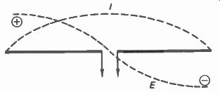
FIGURE 25-6 CURRENT AND VOLTAGE DISTRIBUTION ON HALF-WAVE ANTENNA.
The electron flow in the antenna conductor is not instantaneous but travels along the wire in free space with approximately the speed of light. When the electrons reach the end of the wire, the resulting accumulation of charge at the end provides a potential for moving the charge in the opposite direction, reversing the direction of current flow. The resultant current is zero at the ends, with two currents of equal amplitude flowing in opposite directions.
Farther back on the wire, the outgoing and returning currents are not the same, be cause the charges causing the currents have been supplied to the antenna at different parts of the rf cycle. Maximum current is at the center, where the reflected current from the ends can add to the original current.
The ends of the antenna in free space are points of maximum voltage and zero current.
Because of capacitance of the ends, however, the current is normally not zero at the ends but has a definite value. Therefore, the antenna must be foreshortened to give the same current distribution that would be obtained for a half wave in free space.
The voltage and current distribution illustrate why the physical length of an antenna makes it resonant for a particular frequency.
When the electron charges in the antenna conductor can travel from the center out to the ends and back to the center in the time of one-half cycle, the current and voltage values are maximum. At other frequencies, partial cancellation of the incident and returning electrons reduces the amount of antenna signal.
Harmonic resonances of a dipole. When the antenna is used to receive several channels, the directional pattern and impedance change at higher frequencies because of the different I and E distribution on the conductor. As an example, a A/2 dipole cut for channel 4 at 66 to 72 MHz has a length of 3A/2 for channel 11 at 198 to 204 MHz. The reason is that 198 MHz is the third harmonic of 66 MHz.
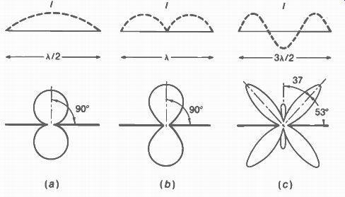
FIGURE 25-7 DIRECTIONAL CHARAC TERISTICS OF CENTER-FED DIPOLE ANTENNA AT
FUNDAMENTAL AND HARMONIC FREQUENCIES (a) FIGURE-EIGHT PATTERN AT HALF-WAVE
RESONANCE, (b) BROADENED RESPONSE FOR FULL-WAVE OPERATION AT SECOND HARMONIC
FREOLENCY, (c) LOBES SPLIT BECAUSE OF HARMONIC OPERATION AT THREE TIMES THE
RESONANT FREQUENCY.
Referring to Fig. 25-7a, the antenna has the figure-eight directivity pattern at its fundamental resonant frequency as a half-wave dipole. The impedance at the center is 72 Ohm.
Maintaining the same physical length, the antenna in Fig. 25-7b is a full-wave center-fed dipole, at double the frequency of Fig. 25-7a.
The dipole still has the figure-eight directivity pattern, but the impedance at the center is now a maximum equal to several thousand ohms.
At three times the fundamental resonant frequency, the same antenna length is three half-waves, as shown in Fig. 25-7c. The center again has minimum impedance, equal to about 100 ohm. However, notice that the directional pat tern splits into four major lobes. There is a gain of 1 dB in the direction of maximum reception, but this is 53° off the ends, with little pickup from the broadside direction.
At 4A and higher harmonics, the response of the dipole splits into more lobes closer to the line of the antenna itself. The conductor then operates as a long-wire antenna, with maximum reception in the direction off the ends. In order to use the broadside response, therefore, a center-fed dipole is limited to a frequency range of 2 to 1 or less.
V dipoles. In order to maintain broadside response over a wider frequency range, the dipole can be angled in the form of a V. For instance, assume the two poles in Fig. 25-7c are moved in 53' to line up with the two forward lobes shown.
Then both top lobes would overlap in the forward direction. The result, therefore, is to maintain the broadside response when the antenna operates at harmonics of its fundamental half-wave resonant frequency. The smaller the angle of the V in the dipole, the higher is the frequency at which the dipole maintains its forward response. Note that the V dipole also has a better front-to-back ratio, as the back lobes spread farther apart. However, "V-ing" the dipole for better response at high frequencies lowers its gain for low frequencies because then the antenna extends less than a half wave length in the space across the ends of the poles.
Capacitive loading of an antenna. The distribution of antenna current and its directional pattern can be altered by inserting series inductance or shunt capacitance. This antenna loading makes the antenna electrically longer.
The reason is that it takes more time for the current to reach the ends of the antenna. For VHF antennas, a technique used sometimes is to mount short metal rods as wings on the dipole, or to use circular disks. This method is equivalent to adding more shunt capacitance, as more time is required to charge the open ends of the antenna.
25- 5 Folded Dipole
s shown in Fig. 25-8, the folded dipole is constructed of two half-wave rods joined at the ends, with one rod open at the center where it connects to the transmission line. The spacing between the rods is small compared with a half wavelength. This half-wave folded dipole has the same directional characteristics as the half wave straight dipole, with the same amount of signal pickup. However, the antenna resistance of the folded dipole is approximately 300 11, which is convenient for matching to 300-ohm transmission line.
The center of the closed section of the half-wave folded dipole is a point of minimum voltage, allowing direct mounting at this point to a grounded metal mast without shorting the signal voltage. Another difference from the straight dipole is that, with operation at twice the fundamental half-wave resonant frequency, the full-wave folded dipole does not have the figure-eight polar pattern, receiving little signal from the broadside direction.
The resistance of the half-wave folded dipole at the center where it connects to the transmission line is higher than the value for a straight dipole because only part of the total antenna current flows in the open section. As a result, the folded dipole antenna resistance wavelength equals 72 ohm multiplied by the square of the ratio of the total diameter of all conductor sections to the diameter of the open section. As an example, in Fig. 25-8, with the same diameter for the two conductor sections, the total diameter is twice the diameter of the open section. Therefore, the antenna impedance is 4 x 72, or 288 II, which is generally considered as 300 ohm.
In applications where a higher resistance is desired for the folded dipole, the diameter of the closed conductor section is increased. In Fig. 25-9a, an additional closed conductor of the same diameter is added, making the total conductor diameter triple the diameter of the open section, to provide an antenna resistance of 9 x 72, or 648 ohm. The same impedance transformation can be obtained by increasing the diameter of the closed conductor, as shown in Fig. 25-9b, instead of adding sections.
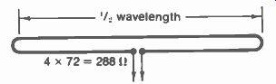
FIGURE 25-8 FOLDED DIPOLE ANTENNA.
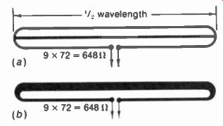
FIGURE 25-9 HIGH-IMPEDANCE FOLDED-DIPOLE ANTENNAS: (a) WITH ADDED CONDUCTOR
ACROSS CENTER; (b) WITH DOUBLE DIAMETER FOR THE CLOSED CONDUCTOR SECTION.
25-6 Broad-Band Dipoles
A thick dipole antenna, which has a cross-sectional dimension approximately 0.1X or greater, can provide more uniform response over a wider band of frequencies, compared with a thin dipole conductor having negligible diameter.
Figure 25-10 shows several types of thick broad band dipoles. These can be constructed of wire conductors, metal sheets, wire screening, or metallic foil. The increased thickness has the following three effects on the dipole characteristics:
1. The antenna resistance decreases and the reactance is lowered even more, resulting in an antenna with lower Q. The antenna has more uniform impedance values over a wide band of frequencies.
2. The broadside response of the directional pattern is maintained over a wider frequency range, before splitting into multiple lobes.
3. More foreshortening is needed with increasing thickness to provide physical lengths equivalent to the electrical wavelengths.
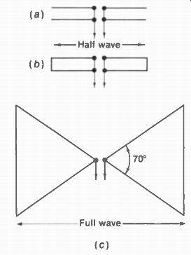
FIGURE 25-10 BROAD-BAND DIPOLE ANTENNAS. (a) HALF WAVE DIPOLE WITH DOUBLE
CONDUCTORS OPEN AT THE ENDS: (b) SAME DIPOLE, BUT WITH CONDUCTORS SHORTED
AT ENDS; (c) FULL-WAVE TRIANGULAR DIPOLE. THIS IS A "BOWTIE" ANTENNA.
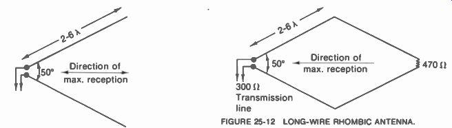
FIGURE 25-11 LONG-WIRE V ANTENNA. FIGURE 25-12 LONG-WIRE RHOMBIC ANTENNA
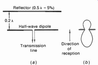
FIGURE 25-13 DIPOLE ANTENNA WITH PARASITIC RE FLECTOR IN BACK.
Referring to Fig. 25-10, the antennas in a and b are operated as half-wave dipoles. When the conductors are separated by 0.1 or less they can be considered as one uniform antenna of wider cross section. The centers are joined in Fig. 25-10a and the ends can also be joined, as in b, since the end points of the two antennas are at the same potential.
The triangular dipole in Fig. 25-10c is operated as a full-wave antenna, however, with a gain of approximately 3 dB. The included angle shown provides an antenna resistance of approximately 300 ohm at the center, for full-wave resonance. Smaller angles result in higher impedance. The overall physical length can be foreshortened about 10 percent. The triangular dipole, often called a bowtie antenna, is commonly used as a broad-band receiving antenna to cover all the UHF channels.
25-7 Long- Wire Antennas
Compared with a half-wave dipole, a long-wire antenna, which is several wavelengths, has the advantages of increased signal pickup and sharper directivity. As the antenna wire is made longer in terms of the number of half waves, the directional pattern changes because of the current distribution, increasing the directivity along the line of the antenna wire itself.
V antenna. When two long wires are combined in the form of the horizontal V antenna shown in Fig. 25-11, the major lobes of the directional pat tern for each wire reinforce along the line bisecting the angle between the two wires. Therefore, the V antenna receives best along the line of the bisector. The greater the electrical length of the conductor legs, the smaller the included angle of the V should be for maximum antenna gain.
Rhombic antenna. A more efficient arrangement is the rhombic antenna shown in Fig. 25-12, which consists of two horizontal V sections. To make it unidirectional, the rhombic antenna can be terminated with a resistor of 470 ohm, for an approximate match to 300-ohm transmission line. Both the V and rhombic antennas are mounted horizontally for horizontal polarization as television antennas. Each leg should be at least two wavelengths at the lowest operating frequency, the gain and directivity of the antenna increasing with the length. The angle of 50° is a compromise value suitable for leg lengths of 2 to 6A. Longer legs should have a smaller angle.' With each leg of four wavelengths, the V antenna has a gain of 7 dB, while the rhombic antenna gain is 10 dB, approximately. At ultrahigh frequencies these lengths are practicable, to provide a high-gain antenna for the UHF television band. The rhombic can provide a uniform value of antenna impedance over a total frequency range of 3 to 1, with high gain and sharp directivity.
'Details of the construction of long-wire antennas are described in the A.R.R.L. Antenna Handbook, published by the American Radio Relay League, Newington, Conn.
25-8 Parasitic Arrays
When current flows in the receiving antenna it radiates part of the intercepted signal. as in a transmitting antenna. If a conductor approximately one-half wave long is placed parallel to the half-wave dipole antenna but not connected to it, as illustrated in Fig. 25-13, the free wire will intercept some of the signal radiated by the antenna. This signal is reradiated by the free wire to combine with the original antenna current. As a result, part of the intercepted signal lost by radiation in the receiving antenna is recovered by using the free wire, providing increased gain and directivity. The free wire is called a parasitic element because it is not connected to the dipole antenna. A parasitic element placed behind the antenna is a reflector; a parasitic element in front of the antenna is a director. The dipole antenna itself, to which the transmission line is connected, is the driven element. This can be either a straight dipole or a folded dipole.
A dipole antenna with one or more parasitic elements is a parasitic array. This is the most common type of television receiving antenna because it is simple to construct, can be oriented easily, provides enough gain for average signal strengths, and increases the directivity compared with dipole alone. The main directional effect of the parasitic element is to reduce the strength of signals received from the rear of the antenna, making its response unidirectional. Therefore, an antenna with a parasitic element is useful for reducing the strength of multipath reflected signals arriving from directions behind the antenna, to eliminate ghosts in the picture.
Dipole and reflector. Referring to Fig. 25-13, the reflector is usually placed approximately 0.2A, or a little less than a quarter wave, behind the dipole, to reinforce signals arriving from the front. Also, the reflector is about 5 percent longer than the dipole, or a little more than a half wave. The antenna response depends on the spacing between the elements, and the tuning of the parasitic, which can be adjusted by changing its length. Closer spacing lowers the antenna impedance and narrows the frequency response. For the typical arrangement shown in Fig. 25-13 the dipole and reflector have a voltage gain of approximately 5 dB. The antenna impedance is about one-half the impedance of the antenna itself, resulting in 150 it for the folded dipole and reflector and 36 ft for the straight dipole and reflector. The front-to-back ratio is approximately 3 dB, resulting in about 1.4 times more signal voltage from the front than from the back.
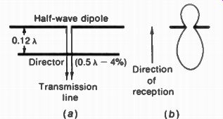
FIGURE 25-14 DIPOLE ANTENNA WITH PARASITIC DIREC TOR IN FRONT.
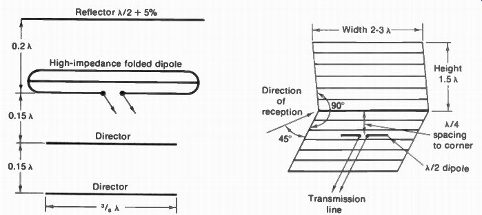
FIGURE 25-15 YAGI ANTENNA ARRAY. WITH DIPOLE, REFLECTOR. AND TWO DIRECTORS
FIGURE 25-16 DIPOLE WITH CORNER REFLECTOR FOR UHF BAND.
It is important to note that the parasitic element is effective only within the frequency range for which it is approximately tuned to half wave resonance. Furthermore, the increase in gain and directivity with a reflector cuts off sharply at frequencies lower than the resonant frequency. For this reason, a dipole with reflector is usually cut for the lowest frequency in the range to be covered. The reflector can then be effective up to a frequency about 30 percent higher than the resonant frequency.
The response of the dipole with reflector can be explained as follows. Signal from the front produces current in the reflector 90° later than in the dipole. The 90 deg lag results because of the reflector spacing and its extra length. Current in the reflector reradiates signal to the dipole, which arrives an additional 90" later.
Meanwhile, the signal at the dipole has varied through 180° of its cycle. The reradiated signal from the reflector, which has been delayed 180° also, then combines with the antenna current in the dipole to provide more signal for the trans mission line. This increase in signal provides a forward gain up to 6 dB, or double the signal voltage of a dipole alone. For signal arriving from the back, however, the reradiated signal from the reflector is just 90 deg out of phase with antenna current on the dipole. The combined signal from the back, therefore, is less than the combined signal from the front.
Dipole with director. Referring to the parasitic director element in Fig. 25-14, it is placed 0.12A in front of the dipole and is about 4 percent shorter than the driven element. The gain and directivity of the dipole with director drop off sharply at frequencies higher than the resonant frequency, which is opposite to the operation of the dipole and reflector off resonance. Practically all television antennas with one parasitic element use a reflector, instead of a director, because the director needs closer spacing for the same gain and front-to-back ratio, which reduces the antenna resistance and narrows the frequency response. For an antenna operating over a relatively narrow frequency, however, directors are combined with a dipole and reflector.
A dipole with one reflector and one director, having the same spacings as for a single parasitic element, provides about 7 dB gain, while the antenna resistance is approximately one-eighth the value of the driven element by itself.
Yagi antenna. A dipole with one reflector and two or more directors, as illustrated in Fig. 25-15, is called a Yagi antenna. This is a compact high-gain array, with a sharp forward broadside lobe and narrow bandwidth, often used in low-signal areas to cover one television channel or several adjacent channels. The gain of the Yagi antenna with three parasitic elements is about 10 dB, with a front-to-back ratio of approximately 15 dB. A high-impedance folded dipole is generally used for the driven element so that the reduced value of antenna resistance with the parasitic elements can be about 150 to 300 ohm. More directors can be added but generally only one reflector is used because additional reflectors do not improve the response.
Dipole with corner reflector. The antenna in Fig. 25-16 has a reflector constructed as a corner conducting sheet behind the half-wave dipole. The corner reflector can be either a solid metal sheet or a grid consisting of wires or wire screening, provided that the spacing between grid wires is 0.1A or less. The dipole antenna, insulated from the parasitic reflector, is mounted along the line bisecting the 90 corner.
Maximum signal is received from the front along this line. The construction of this antenna is practical for the UHF band because of the small size at these frequencies.
25-9 Multiband Antennas
All the television broadcast channels can be considered in three bands: 54 to 88 MHz for the low-band VHF channels, 174 to 216 MHz for the high-band VHF channels, and 470 to 890 MHz for the UHF channels. The main problem in using one dipole for both VHF bands is maintaining the broadside response, as the directional pattern of a low-band dipole splits into side lobes at the third and fourth harmonic frequencies in the 174- to 216-MHz band. A high-band dipole cut for a half wavelength in the 174- to 216-MHz band is not suitable for the 54 to 88-MHz band because of insufficient signal pickup at the lower frequencies.
As a result, antennas for both VHF bands generally use either separate dipoles for each band or a dipole for the 54- to 88-MHz band modified to provide broadside unidirectional response in the 174- to 216-MHz band also. For the UHF band, a VHF antenna can operate as a
long-wire antenna or be used as a reflector sheet behind a broad-band dipole added in front.
Also, an array of very short UHF dipoles can be mounted at the front of the VHF antenna.
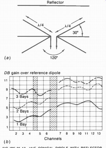
FIGURE 25-17 -- VHF CONICAL DIPOLE WITH REFLECTOR. (a) SPACING OF ELEMENTS,
(b) RESPONSE CURVES FOR CHANNELS 2 TO 13
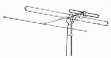
FIGURE 25-18 -- IN-LINE ANTENNA WITH TWO FOLDED DIPOLES AND REFLECTOR FOR
VHF CHANNELS 2 TO 13.
Channels
It should be noted that higher gain is necessary for a UHF antenna to provide the same signal strength as on the VHF channels because the reference dipole is shorter at ultrahigh frequencies. Furthermore, the UHF, band is relatively narrow, as the ratio of 890 MHz to 470 MHz is less than 2:1.
Conical dipole. The VHF dual-band antenna illustrated in Fig. 25-17 is generally called a conical or fan dipole. This antenna consists of two half-wave dipoles inclined about 30' from the horizontal plane, similar to a section of a cone, and usually a horizontal dipole in the middle. All the dipoles are tilted inward toward the wavefront of the arriving signal at an angle approximately 300 from the broadside direction, resulting in a total included angle of 1200 between the two conical sections. Smaller values of included angle reduce the amount of signal intercepted at low frequencies, as the distance across the front is decreased. Either a straight reflector or a conical reflector can be used behind the conical dipole with approximately the same results.
Cut for a half wavelength at channel 2, the conical dipole with reflector is commonly used as a receiving antenna to cover both VHF bands.
The antenna resistance is about 150 Ohm. For the 54- to 88-MHz band, the antenna is a conical type half-wave dipole with a parasitic reflector, providing the desired unidirectional broadside response. For the 174- to 216-MHz band, the tilting of the dipole rods shifts the direction of the split lobes produced at the third and fourth harmonic frequencies, so that they combine to produce a main forward lobe in the broadside direction.
In-line antenna. As shown in Fig. 25-18, this antenna consists of a half-wave folded dipole with reflector for the 54- to 88-MHz band, in line behind the shorter half-wave folded dipole for the 174- to 216-MHz band. The distance between the two folded dipoles is approximately one-quarter wavelength at the high-band dipole frequency. This is the length of line connecting the short dipole to the long dipole, where the transmission line to the receiver is connected.
For the low-band channels, the long folded dipole with reflector supplies antenna signal to the transmission line, as the short dipole has little pickup at these low frequencies. For the high-band channels, the short folded dipole supplies signal to the transmission line, with the long folded dipole operating as a reflector. The directivity pattern of the in-line antenna is relatively uniform on all VHF channels, with a unidirectional broadside response. The average antenna gain is approximately 2 dB on the low band channels and 5 dB on the high-band channels. The antenna resistance is about 150 ohm.
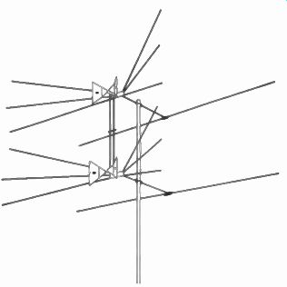
FIGURE 25-19 VHF CONICAL ANTENNA WITH UHF BOWTIE. TWO BAYS STACKED VERTICALLY.
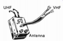
FIGURE 25-20 WV SPLITTER TO SEPARATE VHF AND UHF ANTENNA SIGNALS FOR RECEIVER
LENGTH IS 2-5 IN
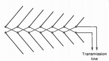
FIGURE 25-21 CONSTRUCTION OF LOG-PERIODIC ANTENNA. DIPOLES ARE DRAWN TO SCALE
TO ILLUSTRATE SHORTER DIPOLES AND CLOSER SPACING FROM BACK TO FRONT.
VHF and UHF antenna. Figure 25-19 shows a VHF conical dipole combined with a UHF bowtie antenna, in two bays, to cover all the television channels. For channels 2 to 6, the conical dipole has a parasitic reflector. For channels 7 to 13, the conical dipoles form a V antenna. On the 470- to 890-MHz band, the conical elements form a reflector for the bowtie antenna. This covers the UHF channels 14 to 83, with an average antenna gain of 6 dB. One downlead from the center of the array is used. At the receiver, the UHF and VHF signals to the antenna terminals on the receiver are separated by a U/V splitter (Fig. 25-20). Log-periodic antennas. The basic construction for a seven-element array is illustrated in Fig. 25-21. The longest dipole is at the back, and each adjacent element is shorter by a fixed ratio, typically 0.9. As an example, with the back dipole 108 in. for channel 2 at 54 MHz, the next length is 90 percent, or 0.9 x 108 = 97.2 in.
Then the next dipole is 0.9 x 97.2 = 87.5 in.
Also, the distance between dipoles becomes shorter by a constant factor, which is typically 35 percent of quarter-wave spacing. As a result, the resonant frequencies for the dipoles overlap to cover the desired frequency band. All the dipoles are active elements, without parasitic reflectors or directors. The active dipoles are interconnected by the crossed phasing harness, which transposes the signal by 180°. When the longest dipole is cut for channel 2, the array will cover the low-band VHF channels from 54 to 88 MHz as antenna resonance moves toward the shorter elements at the front.
For the high-band VHF channels from 176 to 216 MHz, however, the elements operate as 11/2 dipoles. They are angled in as a V. to line up with the split lobes in the directional response for third-harmonic resonance.
When the longest dipole is cut for channel 14 in the UHF band of 470 to 890 MHz, the array can cover all the UHF channels. The V angle is not necessary in the UHF array because this frequency range is less than 2:1.
Figure 25-22 shows a commercial antenna using log-periodic arrays. The larger unit is the VHF antenna for channels 2 to 13. The shorter array at the front is the UHF antenna.
Both are connected to one transmission line for the downlead. At the receiver, a U/V splitter connects the signal to the separate VHF and UHF antenna terminals.
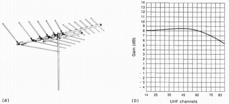
FIGURE 25-22 (a) LOG-PERIODIC VHF ANTENNA WITH UHF DIPOLES AT FRONT. LENGTH
OF CROSSARM OR BOOM IS 10 FT. (b) RESPONSE CURVE OF UHF CHANNELS.
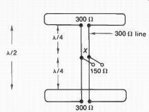
FIGURE 25-23 TWO ANTENNA BAYS STACKED VER TICALLY IN BROADSIDE ARRAY. REFLECTORS
OMITTED FOR CLARITY.
25-10 Stacked Arrays
In order to increase the antenna gain and directivity, two or more antennas of the same type can be mounted close to each other and connected to a common transmission line. The individual antennas are called bays and the combined unit is a stacked array. Mounting the antennas one above the other, as illustrated in Fig. 25-23, is vertical stacking. This can be considered a broadside array, as the antenna receives or transmits best in the direction broadside to the stacking.
In general, stacking can provide an additional gain up to 3 dB for each antenna bay added, since the larger the area of the array, the greater the amount of signal that can be intercepted. To utilize the signal, however, the individual bays must be phased correctly with respect to the common junction for the transmission line, so that the antenna signals can add to provide the required antenna gain with the desired directional response. Rods used for interconnecting the bays in the stacked array are called phasing rods. In phasing separate antennas to a common transmission line, the following points should be noted:
1. A difference of one-quarter wavelength in the distance the antenna signal must travel is equivalent to a phase-angle difference of 90 deg between the two antenna signals.
2. A difference of one-half wavelength is equivalent to a phase-angle difference of 1800.
3. Reversing the connections is equivalent to a phase-angle difference of 180°. With twin lead, a half twist of the line reverses the connections.
Vertical stacking. This is often done in weak signal areas to increase gain and sharpen directivity in the vertical plane, which reduces pickup of external noise from sources usually below the antenna. Figure 25-23 illustrates vertical stacking and how the antenna bays are usually connected to the common transmission line.
Folded dipoles are shown, without reflectors for simplicity, but the same principles apply for any other antenna. The half-wave spacing generally used between stacked antenna bays is convenient for interconnecting them with two quarter wave sections. Because of the symmetry, the antenna signals from both bays travel the same distance to point X and are in phase at the common junction for the transmission line to the receiver. The impedance here is one-half the impedance of either section, as the two lines are in parallel. With more than two antennas in the array, they can be grouped in adjacent pairs, and the pairs are then interconnected to the common transmission line. The horizontal directivity pattern of the vertically stacked array has the same broadside response as the individual antennas, but with more gain.
Undirectional end-fire array. In Fig. 25-24, two antennas are stacked one behind the other a quarter wavelength apart. They are connected to the common transmission line at point X to form an array that has the unidirectional response shown, without any parasitic reflector or director. The arrangement is an end-fire array because it has maximum response through the line of the array. This double V is often used as a VHF antenna. Each V is a dipole, cut for the low band channels but angled in for broadside response on the high-band channels.
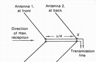
FIGURE 25-24 TWO V ANTENNAS MOUNTED ONE BEHIND THE OTHER IN HORIZONTAL END-FIRE
ARRAY. NO REFLECTORS OR DIRECTORS ARE NEEDED.
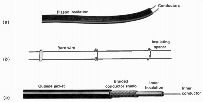
FIGURE 25-25 TRANSMISSION LINES (a) FLAT TWIN LEAD: (b) OPEN-WIRE LINE: (c)
COAXIAL CABLE.
The end-fire directivity results from making the currents in the individual antennas out of phase with each other. With 90° phasing, the response is unidirectional off the end farthest from the transmission line. The antenna to which the transmission line connects is then back of the array. When receiving from the front, antenna 1 intercepts the signal a quarter cycle sooner than antenna 2. However, the quarter-wave line connecting the two antennas delivers this signal at point X in the same phase as the signal intercepted by antenna 2. The array provides a gain of 3 dB, therefore, for signal arriving from the front.
Signal from the back is intercepted by antenna 1 a quarter cycle later than antenna 2.
With the additional quarter wavelength of the connecting line, the signal delivered by antenna 1 arrives at point X 180° out of phase with the signal from antenna 2. The two signals cancel, therefore, resulting in minimum reception from the back.
25-11 Transmission Lines
The main types are shown in Fig. 25-25. The transmission line is just a conductor that has the function of delivering the antenna signal to the receiver. Three important requirements of the line are: (1) minimum losses, (2) no reflections of signal on the line, and (3) no stray pickup of signal by the line itself. To prevent signal pickup, the line should be balanced or shielded or both.
A line is balanced when each of the two conductors has the same capacitance to ground. The balance corresponds to the dipole antenna itself, which has balanced signals of opposite phase in the arms. A balanced line is connected to the opposite ends of a center-tapped antenna input transformer. Then any in-phase signal currents caused by stray pickup by the line can be canceled because of the balanced receiver input circuit. However, the antenna signal from the dipole has opposite phases in the two sides of the line. Then they reinforce each other in the antenna input transformer.
A shielded line is completely enclosed with a metal sheath or braid that is grounded to serve as a shield for the inner conductor. The shield prevents stray signal from inducing current in the center conductor. Usually, the shield is grounded to the receiver chassis. With only one inner conductor, the line is unbalanced.
However, a balancing transformer (balun) can be used. When two inner conductors are used within the shield, the line is both balanced and shielded.
The parallel-wire line in Fig. 25-258 made in the form of a plastic ribbon is generally called twin lead. The type in Fig. 25-25b is open-wire line. These are balanced but not shielded lines.
The coaxial line in Fig. 25-25c is shielded but unbalanced. Shielded lines generally have more capacitance and greater losses. This is shown in Table 25-1, which lists the characteristic impedance and attenuation for the common types of line.
Line losses. The attenuation of the line is caused mainly by PR losses in the ac resistance of the wire conductor. These losses reduce the amount of antenna signal delivered by the line to the receiver. The longer the line and the higher the frequency, the greater the attenuation.
For long runs, the line can have appreciable losses. As an example, 200 ft of RG-59U coaxial cable has about 6 dB attenuation for 100 MHz, which means a loss of one-half the signal. The losses are even greater in the UHF band of frequencies. At 500 MHz, the RG-59U cable has an attenuation of 8.3 dB per 100 ft, compared with 3.7 dB at 100 MHz. Note that RG-11U has less losses than RG-59U.

TABLE 25-1 TRANSMISSION LINES ------- Flat twin lead is also available in Z„ of 75 ohm and 150 ohm.
I V is ratio of velocity in dielectric to velocity in free space.
The characteristic impedance (Z ) of the line depends on the size of the wire conductors and their spacing. Uniform spacing of the conductors is what makes a transmission line with a characteristic Z. Wider spacing results in higher Z . In practical terms, Z is just the impedance needed to terminate the line to prevent reflections from the end. Two important factors about the characteristic impedance are: (1) Z„ is an ac value that cannot be measured with an ohmmeter, and (2) Z„ is a characteristic that is the same for a line of any length. A 1-ft length and a 100-ft length of the same type of line have the same Z. However, the longer line has more attenuation losses.
Flat twin lead. This is the type of line generally used for television receivers because it has low losses, is available with 300-ohm Z , costs less, and is flexible for ease of handling. The plastic is a dielectric such as polyethylene, with the parallel conductors embedded in the ribbon. For 300-ohm Z , the spacing is typically 3/„ in. between conductors of gage number 20 to 22. The 75- and 150-ohm twin lead have closer spacing.
Since television receivers have a balanced input impedance of 300 ohm, the twin lead of 300-ohm Z, is convenient for matching the transmission line to the receiver. With the receiver end matched to prevent reflections, an impedance match at the antenna end may not be necessary.
There are different qualities of twin lead with the same 300-ohm Z„. Stronger line is prefer able for outside use because it lasts longer.
Also, thicker conductors, with a lower gage number, have less losses.
The attenuation of flat twin lead increases when the line is wet, especially for old line with tiny cracks that absorb water. Ultraviolet light from the sun causes stresses in the plastic which produce almost invisible cracks that collect moisture and dirt, increasing the line losses.
Foam twin lead. This type has the two conductors embedded in polyethylene foam, for low losses, especially for the UHF band of frequencies. The twin line is encased in a strong plastic jacket for protection against the weather.
Shielded twin lead. This type is encased like the foam line, but a shield of solid aluminum foil inside the jacket surrounds the twin lead. It may also have a drain wire connected to the receiver chassis to remove static charges.
Coaxial cable. As illustrated in Fig. 25-25c, this line consists of a center conductor in a dielectric that is completely enclosed by a metallic shield.
This may be tubing or a flexible braid, of copper or aluminum. A plastic jacket is molded over the entire line as a protective coating. This line is practically immune to any stray pickup because the outer conductor acts as a grounded shield.
In effect, the inner conductor is one side of the line and the conductor shield is the other side.
Coaxial cable is used in noisy locations, or where stray pickup of interfering signals by the line is a problem, and where multiple lines must be run close to each other. In cable distribution systems, coaxial cable is usually a necessity, in spite of its losses. The types generally used for television are RG-11U, with an outside diameter of 0.4 in. for Z of 75 ohm and RG-59U, with a diameter of 0.24 in. for Z of 73 H. Foam coaxial cable. This type is also available with foam dielectric. This reduces the attenuation about 15 percent at 100 MHz and 25 percent at 500 MHz. Also, the velocity factor V in Table 25-1 is 0.81 with foam dielectric.
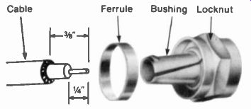
FIGURE 25-26 F-TYPE CONNECTOR FOR COAXIAL CABLE.
F-connector. See Fig. 25-26. This type is often used with coaxial cable. The center conductor of the cable itself is the connecting pin, which eliminates soldering on the male plug. A soft ferrule ring is crimped around the shield to hold the cable. Usually, a locking nut is screwed down to make a tight connection to the female fitting.
25-12 Characteristic Impedance
When the transmission line has a lengthcom parable with a wavelength of the signal frequency carried by the line, the line has important properties other than its resistance. The small amount of inductance of the conductor and the small capacitance between conductors are distributed over the entire length of the line. The result is a distributed inductance and capacitance which can make the line a reactive load, equivalent to lumped reactance in an ordinary circuit. Furthermore, the uniform spacing between conductors provides constant inductance and capacitance per unit length. Therefore, the characteristic impedance can be defined in electrical terms as:
'C Z„ = 11 N I C (25-3)
Z is in ohms, L the inductance per unit length in henrys, and C the shunt capacitance per unit length in farads. As an example, assume a line with 0.54 u-H inductance per foot for both conductors and 6 pF capacitance. Then:
./ x 1 0 54 0 6 , Z„ = V = V 0.09 x 10^6 = 0.3 x 10^6 x 10-' 2 Z„ = 300 ohm
The closer the conductor spacing, the greater the capacitance and the smaller the Z„ of the line.
Physical characteristics. In terms of physical construction, Z„ depends on the conductors and their spacing. For parallel-conductor line with air dielectric, Z„ = 276 log.-- 12 (25-4)
where s is the distance between centers and r is the radius of each conductor, with s and r both in the same units. As an example, for open-wire line, No. 12 gage wire has a radius of 0.04 in.
With 1-in, spacing, the ratio of sir equals 1/0.04, or 25. The log of 25 is 1.398. Therefore, Z„ is 276 x 1.398, which equals 386 ohm. For air-insulated coaxial line, Z„ = 138 log - d„ 12 (25-5) d, where d„ is the diameter of the outside conductor and d, the diameter of the inside conductor.
As an example, No. 18 wire for the inside conductor has a diameter of 0.08 in. If the diameter of the outside conductor is '/, in. the ratio of d„/d, then is 0.250/0.08, or 3.125. The log of 3.125 is 0.4949. Therefore, Z„ equals 138 x 0.4949, or 6812.
Resonant and nonresonant lines. When the line has a resistive load equal to Z„ connected across the end, all the energy traveling down the line will be used in the load. Maximum power transfer results, and no energy is reflected back into the line. This termination of the line in its characteristic impedance makes it effectively an infinitely long line. The reason is that the line has no discontinuity at the load when the load equals Z. The effect is the same as though the line had no end. Such a line terminated in its Z„ is a nonresonant or flat line because there are no reflections. Then the length of the line s not critical.
When the transmission line has a termination not equal to 4, the current will be reflected from the end. The result is standing waves of E and I, just as on an antenna. This effect makes the line resonant. Its length is critical because a connection at different points on the line has different values of signal.
The ratio of the voltage at a maximum point to the voltage at a minimum point is defined as the voltage standing-wave ratio, abbreviated VSWR. For a non-resonant line terminated in Z„, the VSWR is 1. For a resonant line not terminated in Z„, the VSWR is more than 1.
The greater the mismatch of the load to the Z„ of the line, the higher the VSWR of the line The extreme case of a resonant line with a high VSWR is either a short or open at the end.
As a practical application of a non-resonant line, assume 300-a twin lead is connected to the 300 ohm antenna input terminals on the receiver. The line can be cut at any length because there are no standing waves. However, more length still produces more PR losses.
Also, any extra length should not be coiled because of the inductive effect. If you add hand capacitance to a non-resonant line by touching it, there will be either little effect or less signal. If you touch a resonant line, the result can be much more or much less signal, but only at particular points on the line for different frequencies.
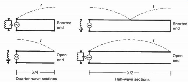
FIGURE 25-27 TRANSMISSION-LINE SECTIONS AS RESONANT CIRCUITS.
TABLE 25-2 RESONANT LINE SECTIONS
25-13 Transmission-Line Sections as Resonant Circuits
When the transmission line is not terminated in its characteristic impedance, the values of current and voltage change along the line, the magnitudes varying with a wave motion that is the same as for an antenna. Therefore, the impedance for different points on the line varies from maximum at the point of highest voltage on the line to minimum at the point of highest current, as the impedance at any point equals the ratio of voltage to current. This is illustrated in Fig. 25-27 showing transmission lines being used as resonant circuits. Since the action of the line in such an application depends on the existence of reflections, the lines are not terminated in their characteristic impedance but are either shorted or open at the end in order to produce the maximum standing-wave ratio and the highest 0 for the equivalent resonant circuit.
In analyzing the action of the transmission-line sections, it should be noted that an open end must be a point of maximum voltage, minimum current, and maximum impedance.
For the opposite case, a shorted end must be a point of maximum current, minimum voltage, and minimum impedance. For each length equal to a quarter wave back from the end of the line the voltage and current values are reversed from maximum to minimum or vice versa. Inter mediate values of impedance are obtained for points along the line between the maximum and minimum points.
In Fig. 25-27 it is shown that a quarter wave section shorted at the end is equivalent to a parallel-tuned circuit at the generator side because there is a high impedance across these terminals at the resonant frequency. For a length shorter than a quarter wave the line is equivalent to an inductance.
The open quarter-wave section provides a very low impedance at the generator side of the line. A length less than a quarter wave makes the line appear as a capacitance.
The half-wave sections, however, repeat the impedance at the end of the line to furnish the same impedance at the generator side. A half wave corresponds to a half-cycle of signal, though, with a phase reversal of the voltage and current. The main features of N/4 and A/2 sections are summarized in Table 25-2.
Transmission-line sections are often called stubs. These can be used for
1. Impedance matching
2. An equivalent series resonant circuit to short an interfering rf signal
3. Phasing signals correctly in antennas For phasing sections, a quarter wave produces a 90° change in phase angle between the signal at the input and output ends. A half wave section shifts the phase by 180'. To reduce interference, an open A/4 stub at the interfering signal frequency can be used.
One side is connected across the antenna input terminals on the receiver, while the open end produces a short at the receiver input one quarter wave back. The same results can be obtained with a half-wave stub shorted at the end.
25-14 Impedance Matching
This means making the impedance of the load equal to the impedance of the generator or source, for maximum power transfer. In the receiver antenna system, the transmission line is the load for the antenna, while the receiver input circuit is the load for the line. A mismatch at either end causes a loss of signal. In addition, reflections can be produced on the line when all the energy is not absorbed at the load. However, only one end need be connected to its characteristic impedance to eliminate standing waves on the line, since there cannot be any reflections from the matched end.
General practice is to use 300-it twin lead to match the receiver input. This impedance is designed to be approximately constant for all channels. As a result, the impedance match is maintained throughout the television band for maximum transfer of signal from the line to the receiver and to eliminate reflections in the line.
Matching the impedance of a multiband antenna to the Z of the transmission line is usually not critical. The reason is that the antenna impedance may vary over a wide range for different channels, as the electrical length of the antenna changes for different frequencies. An impedance mismatch of 2.5 to 1 results in a 1-dB loss of signal.
Quarter-wave matching section. When a quarter-wave section of transmission line with a characteristic impedance Z„ is neither shorted nor open at the end but has an impedance Z, connected across one end, the impedance at the other end Z, is Z 2 or Z, = Z,Z2 (25-6) Z,
Zu is the geometric mean of Z, and Z2. Therefore, if a quarter-wave section of line having an impedance equal to V'Z,Z, is used to couple two unequal impedances Z, and Z2, the section will provide an impedance match at both ends.
Referring to Fig. 25-28, a 35-ohm antenna is used with 300 ohm line, and the matching section has an impedance equal to V35 x 300, or approximately 100 ohm. This equivalent quarter wave matching transformer is often called a Q section.
The length of the quarter-wave section is calculated for the desired frequency from the formula 246 = V x 4 f(MHz) (25-7)
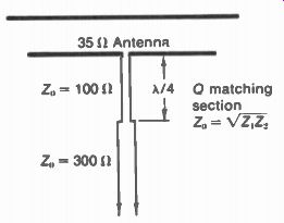
FIGURE 25-28 QUARTER-WAVE SECTION MATCHING ANTENNA TO TRANSMISSION LINE.
V is the velocity factor, which depends on the velocity of propagation along the line. This is less than the speed of light because of the reduced velocity in solid dielectric materials. Values of the velocity factor V are listed in Table 25-1 for different types of line. As an example, a quarter wave matching stub at 67 MHz using twin lead would have a length of 2.9 ft.
The quarter-wave matching section has the advantage of producing an impedance match with very little attenuation of the signal, but the section can provide a match only for frequencies at which it is approximately resonant. However, the stub functions in the same way when its length is 3/ 4A or any odd multiple of a quarter wave. Therefore, it can be cut to serve for both the low- and high-frequency VHF television bands.
Balancing unit. Two Q sections can be combined to make the balancing and impedance transforming unit illustrated in Fig. 25-29. This is called a balun, for matching between balanced and unbalanced impedances, or an elevator transformer. At one end, the two 150 ohm quarter-wave sections in Fig. 25-29a are connected in parallel, resulting in 7541 impedance across points A and B. Either A or B can be grounded to provide an unbalanced impedance at the ungrounded point with respect to ground.
At the other end, the two 150-ohm quarter-wave sections are connected in series to provide 300 ohm impedance between points C and D. The quarter wavelength of line isolates the ground point from C or D, allowing a balanced impedance with respect to ground.
Either side of the balun can be used for input, with the opposite side for output. Useful applications are matching 72-ohm coaxial line to 300 ohm receiver input or, in the reverse direction, 300 ohm twin lead to 75 ohm unbalanced input.
The equivalent transformer in Fig. 25-29b shows how bifilar windings are used to simulate the 150 ohm transmission-line sections. This small transformer is inside the balun unit in Fig 25-29c. The windings are usually on a ferrite core to increase the inductance, which makes the line electrically longer. The 75 ohm side has a jack to take coaxial cable, while the 300-ohm side has twin-lead terminals.
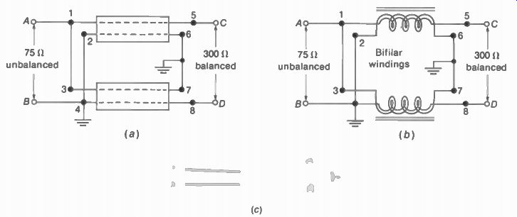
FIGURE 25-29 BALANCING UNIT (BALUN) TO MATCH BETWEEN 75-ohm UNBALANCED AND
300-I) BALANCED Z. (a) WITH A/4 MATCHING SECTIONS: (b)EQUIVALENT TRANSFORMER;
(c) TYPICAL UNIT. LENGTH IS 3 IN.
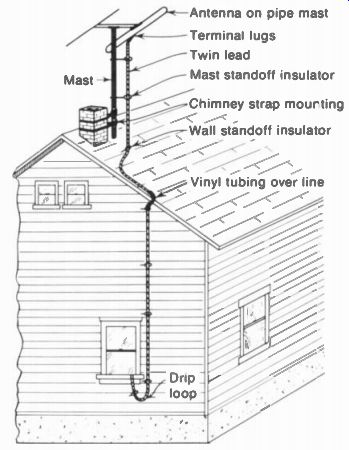
FIGURE 25-30 AN ANTENNA INSTALLATION.
25-15 Antenna Installation
A typical installation is illustrated in Fig. 25-30 for a private house in a suburban area. A mounting with chimney straps is shown, but a roof mount or wall mount can be used instead.
Mount the antenna near a line of sight, broad side to the transmitter, and as high as possible.
Increased height results in more antenna signal and less interference. The antenna should be at least 6 ft away from other antennas and large metal objects.
A suburban location 25 to 35 mi from the transmitter can be considered an average installation with one antenna array. Farther away, larger antennas and two or more bays stacked vertically may be necessary for sufficient antenna signal, especially on the UHF band. With multiple bays and antennas having a long cross arm, it probably will be necessary to use a roof mount with guy wires to hold the antenna mast steady in the wind. An antenna is usually in stalled in good weather, but remember, it must be able to hold up in bad weather.
Locations in crowded city areas close to the transmitter but surrounded by tall buildings can have very weak signal with severe reflections. Changing the antenna placement only a few feet horizontally or vertically can make a big difference in signal. The reason is that standing waves of signal are set up in areas where there are large conductors nearby, especially between buildings.
Antenna orientation. Before being clamped tight in its mounting, the antenna is rotated to the position that results in the best picture and sound. For suburban locations and fringe areas, the best orientation is usually broadside to the transmitter location. In city areas, however, the antenna may receive more signal over a reflected path from a high building nearby.
Antenna rotator. This is a motor which turns the antenna mast, operated by a remote control at the receiver. The rotator is very useful when channels must be received from different directions. One example is a town between two big cities that have most of the television stations.
In addition, in any installation a rotator can be helpful in finding the best antenna orientation.
A special cable is used, with conductors for the antenna signal and power to the rotator.
Selecting the transmission line. In most cases, 300-ohm twin lead is used. For long runs, heavy duty foam twin lead is preferable. The open wire line may be necessary for the extreme case of a long run that must have minimum losses.
When there is a problem of pickup of noise and interference by the line, coaxial cable is generally used. In locations where the trans mission line must be run down a corner of an apartment house parallel to many other lines, for instance, shielded line is preferable in order to minimize pickup of interference from the other lines. Shielded coaxial cable is the type used in cable distribution systems for multiple receivers.
The transmission-line run. It should be as short as possible. Excess line is cut off in order to minimize attenuation of the signal. Do not coil extra line because the inductance acts as an rf choke to reduce the signal. Twin lead is generally twisted about one turn per foot to improve the electrical balance and strengthen the line mechanically so that it does not flap too much in the wind.
Grounding. To prevent accumulation of static charge on the mast, it can be grounded by connecting a heavy ground wire to a cold-water pipe or to a metal stake driven into the earth. In some areas, local regulations require grounding the mast.
Lightning arrestor. When the antenna is a high point in the area, a lightning arrestor should be installed on the transmission line. The lightning arrestor provides a high-resistance discharge path that prevents static charge from ac cumulating on the antenna; and, if lightning should strike the antenna, the arrestor is a short circuit to ground that protects the receiver. In doors, the lightning arrestor is usually mounted by a grounding strap on a cold-water pipe. For use outdoors, a weatherproof type of arrestor can be installed on a grounded mast.
Impedance-matching applications. It is best to use transmission line having a characteristic impedance which is the same as the input impedance of the receiver, since then a match at one end of the line is approximately maintained for all channels. This generally means using 300-ohm line. The impedance match can be checked by noting the effect of added capacitance when you touch the line. When your hand capacitance at any position on the line de creases the picture strength, this indicates the impedance match is correct.
At the antenna, it is preferable not to match to a higher value of line impedance when the antenna is used for several channels and is cut for the lowest frequency. The antenna impedance then increases with frequency and the mismatch allows a broader frequency response in terms of antenna signal delivered at the receiver. If the antenna is used for only one channel, however, more signal can be obtained by matching the antenna to the transmission line, using a quarter-wave matching section.
When 72-ohm coaxial cable is used in order to have a shielded transmission line, it can be matched to 300 ohm by means of a balun.
Indoor antennas. These can be used in strong-signal locations without ghosts. Most common is a simple dipole assembly with tele scoping rods of adjustable length. The rods are extended to full length for the low-band VHF channels. Shortening the rods provides half wave resonance for the high-band channels. A convenient indoor antenna for just two or three channels is a folded dipole formed from 300-ohm twin lead, as shown in Fig. 25-31.
The location of an indoor antenna is usually determined by trial and error to find the spot that provides the most signal. The best position is not always horizontal because the antenna pickup is generally reflected signal from nearby conductors, which is usually not horizontally polarized.
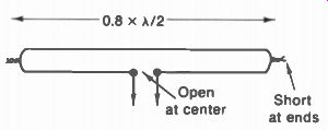
FIGURE 25-31 FOLDED DIPOLE ANTENNA MADE WITH 300-ohm TWIN LEAD
Another possibility is a power-line antenna, where one antenna input terminal is connected to the high side of the ac power line through an rf coupling capacitor of about 100 pF. The signal return path is to earth ground, through stray capacitance. However, the antenna signal is usually weak, depending on peaks and nodes for standing waves of rf signal on the power line.
Built-in antennas. With portable receivers, a telescoping dipole assembly is often mounted on the cabinet. When a single pole is used for a monopole antenna, it operates as a grounded quarter-wave type, connected to the receiver input with a balun. For UHF reception a single turn loop antenna is used. The diameter is about 8 in., making the loop conductor several wave lengths for the UHF channel frequencies.
If the built-in antenna is used, the location and orientation of the receiver cabinet can make a big difference in the amount of antenna signal.
When it is not being used, the built-in antenna should be disconnected from the receiver input terminals, using only the external antenna Attic antennas. In a private house, an outdoor type of antenna can usually be mounted in the attic with good results. Since wood and brick are insulators, they have very little effect on the antenna signal. However, sheets of aluminum insulation can reduce the signal level.
25-16 Multiple Installations
When multiple receiver outlets from a common antenna system are needed, there are three main requirements:
1. The amount of antenna signal available for each receiver must be at least several hundred microvolts for a good picture with out excessive snow. In addition, the signal from the antenna distribution system must be much greater than the amount of signal picked up directly by the transmission line or receiver chassis, without the antenna. Otherwise, there can be ghosts in the picture caused by duplicate signals.
2. Isolation should be provided between receivers to attenuate the local oscillator signal, which can produce beat-frequency interference patterns consisting of diagonal bars in other receivers on the common distribution line.
3. The impedance of the transmission line should be matched at the receiver end. This is important with a long line, to prevent ghosts caused by reflections on the line, or when the impedance match is necessary for maximum signal to provide a satisfactory picture.
Considering these requirements, it may be useful to note that several receivers can simply be connected in parallel to one transmission line, with adequate results if there is enough antenna signal, local oscillator interference is no problem, and the transmission line is less than about 50 ft long.
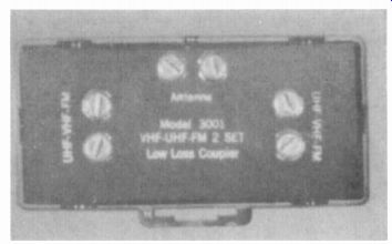
FIGURE 25-32 TWO-SET COUPLER. LENGTH IS 2V., IN. (THE FINNEY Co)
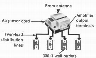
FIGURE 25-33 AMPLIFIED DISTRIBUTION SYSTEM FOR FOUR OUTLETS. (JERROLD ELECTRONICS
CORPORATION)
Multi-set coupler. As shown in Fig. 25-32, this is a small, inexpensive unit designed to provide multiple 300-ohm output terminals for two to four receivers, with 300-ohm input for the line from the antenna. Since no amplifier is included, a strong antenna signal is necessary because the coupler attenuates the distributed signals for each set.
Amplified distribution systems. When there is not enough antenna signal to operate several receivers, or when many receivers must be fed from a single antenna system, as in apartment houses, hotels, and motels, a master antenna distribution system using rf amplifiers is necessary. Furthermore, if individual antennas must be used for different channels, the amplifiers provide a means of mixing the antenna signals for common distribution. Signal for the FM broadcast band of 88 to 108 MHz is usually provided also to feed FM receivers. Coaxial cable is generally used for long distribution lines, as it is shielded against noise and direct pickup of signal.
More details of cable distribution systems are described in the next SECTION. However, Fig. 25-33 illustrates a relatively simple amplified system with twin lead for distribution to four receivers. These lines should not be run close together. Also, any branch not used must be terminated with a 300-ohm resistor. Otherwise, oscillations in the amplifier or reflections in a line can be coupled to all the other lines, causing interference patterns in the receivers. This type of distribution system is convenient for installation in a private home, with the antenna and amplifier in the attic.
25-17 Troubles in the Antenna System
The trouble symptom of weak picture with excessive snow, on either some channels or all channels, is often caused by insufficient antenna signal. Also, ghosts in the picture can be eliminated only by providing antenna signal without any reflections.
When the transmission line is open, the line serves as an antenna. The signal may actually be stronger than normal on some channels but very weak on most channels. If the signal is better with only one side of the line connected to the receiver input, this effect shows the line is open.
The transmission line can be checked for continuity by an ohmmeter. Remember that the ohmmeter cannot indicate characteristic impedance but only dc resistance. With a folded dipole antenna connected to the line, it should have practically zero resistance at the receiver end to indicate continuity. With other antenna types, the line can be temporarily shorted at one end to check continuity at the opposite end.
If the transmission line is intermittently open, it will produce flashing in the picture, especially in windy weather. Flashing can also be caused by static discharge of the antenna when there is no lightning arrestor. If the signal is weak only in rainy weather, this usually means worn insulation on the line, which absorbs too much water, causing excessive losses for the antenna signal input to the receiver.
For the UHF channels, vibration of the antenna may produce fading of the picture, be cause of the very short wavelengths. Clean, tight contacts at the antenna are especially important for ultrahigh frequencies to avoid intermittent connections and loss of signal caused by leakage across the terminals.
SUMMARY
1. The length of a half-wave dipole equals 462/f, where f is in MHz to calculate the half wavelength in feet. The antenna is horizontal for signals with horizontal polarization. The impedance at the center of a straight dipole is 72 ohm. The characteristics of a half-wave folded dipole are similar to the straight dipole but the impedance at the center is 300 ohm.
2. The polar directivity pattern of a half-wave dipole is a figure eight, showing maximum reception broadside and minimum off the end of the antenna. At harmonic frequencies, however, the broadside response decreases and reception increases off the ends. For this reason, dipoles are often angled in a V to improve the broadside response for higher frequencies.
3. Front-to-back ratio compares how much more signal the antenna receives from the front than the back. A ratio of 2:1 equals 6 dB.
4. Antenna gain indicates how much more signal an antenna array can receive, compared with a half-wave resonant dipole. A voltage gain of 2 equals 6 dB.
5. Ghosts in the picture are generally caused by reflected signal received by the antenna, in addition to direct signal from the transmitter. A directional antenna, with a narrow forward lobe, can eliminate ghosts.
6. A parasitic reflector mounted behind the dipole increases the antenna gain and front-to-back ratio, to minimize ghost problems. See Fig. 25-13 for length and spacing. However, a parasitic director is mounted in front of the dipole. See Fig. 25-14 for length and spacing.
7. A Yagi antenna is a parasitic array with one reflector and two or more directors.
Its features are high gain and good front-to-back ratio with a narrow forward lobe, but relatively narrow bandwidth.
8. Antennas can be stacked vertically one above the other to increase the broad side response of the array. See the broadside array in Fig. 25-23.
9. Antennas can be stacked horizontally one behind the other to increase the response through the line of the array. See the double-V end-fire array shown in Fig. 25-24.
10. The main types of transmission line are flat twin lead and coaxial cable. The coaxial line is shielded but unbalanced. Flat twin lead is most common because it is economical, it has low losses, and its 300-ohm impedance matches the receiver input impedance.
11. The characteristic impedance Z = L/C, where L is the inductance and C the capacitance per unit length of line. Z, is independent of length.
12. Insufficient antenna signal results in a weak, snowy picture. Then interference in the picture is more noticeable and synchronization is poor because of the weak signal.
Self-Examination (Answers at back of guide)
Choose (a), (b), (c), or (d).
1. The length of a half-wave dipole at 100 MHz is: (a) 4 m; (b) 4.62 ft; (c) 100 ft; (d) 100 m.
2. To eliminate ghosts in the picture : (a) use a longer transmission line; (5) connect a booster; (c) change the antenna orientation or location; (d) twist the trans mission line.
3. In Fig. 25-2, the antenna signal for a transmitter 600 off the ends equals: (a) 100 µV; (b) 300 µV; (c) 600 µV; (d) 800 V.
4. A Yagi antenna features: (a) stacked V dipoles; (b) two or more driven elements; (c) high forward gain; (d) very large bandwidth.
5. Which of the following is false for a dipole with reflector? (a) It should be cut for the lowest channel. (b) Gain is increased in the forward direction. (c) Front-to back ratio is increased. (d) The line should be connected to the reflector.
6. Which of the following is true? (a) Angling a dipole in a V improves the response for low frequencies. (b) A folded dipole cannot be angled in a V. (c) The impedance of a folded dipole is 300 ohm. (d) The impedance of a straight dipole is 300 Ohm.
7. Which of the following applies to 300-ohm twin lead? (a) Low losses, shielded and unbalanced; (b) high losses, unshielded and unbalanced; (c) low losses, shielded and balanced; (d) low losses, unshielded and balanced.
8. A nonresonant or flat line has no reflections regardless of length because it: (a) is usually very short; (b) is usually very long; (c) has low value of Z„; (d) is terminated in Z.
9. Which of the following is true? (a) A reflector is in back of the antenna. (b) A director is in back of the antenna. (c) A reflector is connected to the line. (d) A director is connected to the line.
10. Which of the following is true? (a) Characteristic impedance can be measured with an ohmmeter. (b) Twin lead has lower line losses when wet. (c) An open twin-lead line can serve as an antenna. (d) Shielded line picks up more signal than unshielded line.
Essay Questions
1. Define the following terms: antenna gain, front-to-back ratio, parasitic element, harmonic antenna, broadside array, end-fire array.
2. Show a straight dipole antenna with length cut for 54 MHz. Also for 174 MHz. Do the same for folded dipole antennas.
3. What is the cause of a ghost in the picture? Why is the ghost usually to the right of the main image?
4. Show the polar directivity pattern of a half-wave dipole alone, and with a reflector. List two differences between the patterns.
5. A dipole is cut for half-wave resonance at 54 MHz. Show its polar directivity pat tern at 54 MHz and at its third harmonic frequency of 162 MHz.
6. Which is more desirable to minimize ghosts: narrow bandwidth or a narrow forward lobe for the antenna response? Explain why.
7. List the velocity factors for twin lead, coaxial cable, and open-wire line. Why is the velocity factor for twin lead less than for open-wire line?
8. A ghost caused by multipath reception is 2 in. to the right of the main image, on a raster 20 in. wide. What is the difference in length between the direct and reflected signal paths?
9. Explain briefly how multiple ghost images can be caused by a long transmission line. What is a minimum line length that will produce a noticeable ghost?
10. Explain briefly how a ghost could be produced to the left of the main image. Assume the ghost image varies in strength when a person walks near the receiver.
11. Give three methods of reducing ghosts caused by multipath antenna signals.
12. Give two advantages of dipole with reflector, compared with a dipole alone.
13. Give two differences between a parasitic reflector and parasitic director.
14. Give two advantages and one disadvantage of a Yagi antenna.
15. Draw a folded dipole with an impedance of approximately 1,200 S2 at the center.
16. Describe briefly five types of television receiving antennas, giving one important feature of each.
17. Give two features of an LPV antenna.
18. Describe briefly how the directional pattern of a dipole cut for 54 MHz changes from channel 2 to channel 6 to channel 13.
19. Explain briefly why a long-wire V antenna receives best along its center line.
20. Explain briefly why an end-fire double-V array does not need a reflector.
21. Give one example where coaxial line would be preferable to twin lead for a line length of 100 ft to the external antenna.
22. Why is the transmission line terminated in its characteristic impedance?
23. Compare Z„ and one additional feature for flat twin lead and RG-59U coaxial cable.
24. Distinguish between a resonant line and a flat (nonresonant) line. Why is a resonant line critical in length, while a flat line is not? How do they compare in VSWR?
25. Describe briefly five main parts of an antenna installation job.
26. What are two problems to consider when connecting multiple receivers to a common antenna?
27. Why does a weak picture with snow indicate the trouble may be insufficient antenna signal? Give one other cause of this trouble symptom.
28. Give two indications of an open transmission line.
Problems (Answers to selected problems at back of guide)
1. Referring to Fig. 25-2, tabulate the values of antenna signal at 90 deg , 120°, 150°, and 180'.
2. Redraw Fig. 25-2 for an antenna with 6 dB gain, compared with the antenna shown, and front-to-back ratio of 6 dB.
3. Calculate the length of a half-wave dipole with reflector and give spacing, in feet, for 54 MHz.
4. Calculate the lengths for a straight dipole with reflector cut for 54 MHz and a folded dipole with reflector cut for 174 MHz. Show the two antennas with separate lines to a double-pole double-throw knife switch.
5. Calculate the length in feet of a half-wave folded dipole made of twin lead and cut for 98 MHz.
6. Show a X/4 Q section made of twin lead, matching 300-ohm line to a 72-ohm antenna.
Calculate length and Z„ for the Q section.
7. Calculate length in feet of a folded dipole for the center frequency of channel 11.
8. (a) Draw a Yagi antenna for channel 11, showing lengths and spacings for the folded dipole, reflector, and two directors. (b) Show two of these Yagi antennas stacked vertically, with two alternate methods of phasing the antennas to a common transmission line.
9. What is the length in feet for each leg of a rhombic antenna 2x long at 470 MHz?
10. (a) Draw a double-V end-fire array, showing length and spacing for 69 MHz. (b)
Show two of these double-V antennas stacked vertically, with two alternate methods of phasing the antennas to a common transmission line.
11. Using Eq. (25-5) for air-insulated coaxial line, what is the Z„ for d„ = 0.64 in. and d, = 0.2 in.? 12. Calculate Z„ for the following examples of parallel-conductor line with air insulation: (a) L = 0.225 µH/ft, C = 1 pF/ft. (b) Conductors of 0.04 in. radius with 0.6-in. spacing. (c) No. 18 gage wire conductors spaced 0.5 in. apart.