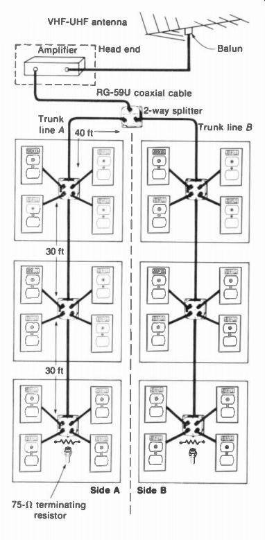
The requirements of cable distribution systems are illustrated by the system in Fig. 26-1, which delivers antenna signal for the VHF and UHF channels to 24 television receivers. Note the symmetry, with two identical trunk lines of 12 sets each. Sufficient signal is provided by the head end, which consists of an amplifier fed by the master antenna. A two-way splitter divides the amplified output for trunk lines A and B. In the trunk line, four-way multi-taps are used. Each taps off part of the signal to wall outlets for a group of four receivers. This layout would be for a dealer's showroom, to operate 24 sets from one antenna. Each receiver should have a signal of approximately 1 to 5 mV. All the distribution lines use coaxial cable with a nominal impedance of 75 O. The amplifier gain and the distribution losses are generally expressed in decibel (dB) units because these values can be simply added or subtracted. More de tails are explained in the following topics:
26-1 Head-end equipment
26-2 Distribution of the signal
26-3 Types of distribution losses
26-4 Calculation of total losses
26-5 System with multi-taps
26-6 System with single taps at wall outlets
26-7 Decibel (dB) units
26-8 Decibel conversion charts
FIGURE 26-1 CABLE DISTRIBUTION SYSTEM FOR 24 RECEIVERS WITH FOUR-WAY MULTITAPS FOR GROUPS OF FOUR WALL OUTLETS. SEE TEXT FOR EXPLANATION.
26-1 Head-End Equipment
This consists of the antenna and amplifier to feed signal into the main line for the splitter to the trunk lines. Note the following possibilities for the antenna:
1. Multiband antenna for the VHF channels
2. Multiband antenna for the UHF channels
3. All-channel antenna for the VHF and UHF channels
4. Separate antennas for each channel, using a high-gain Yagi array with a narrow forward lobe to reduce ghosts
When all stations are in the same direction, an all-channel antenna can generally be used. The amplifier provides the required gain. When UHF channels are to be received, they can be converted to unused VHF channels in order to reduce line losses for the distribution system.
The function of the amplifier is to provide the amount of gain needed to make up for the distribution losses. Then each receiver has the signal it would have as a single installation. The signal required for each receiver is at least 1 mV for no snow in the picture, but less than 5 mV to prevent overload distortion. The antenna signal can be determined with a field-strength meter (Fig. 26-2). Or, a battery-operated portable receiver can be connected temporarily to the antenna in order to judge the picture.
VHF amplifier. This amplifies all the VHF channels (2 to 13), with a typical gain of 45 dB. UHF amplifier. This amplifies all the UHF channels (14 to 83), with a typical gain of 45 dB. More gain will usually be needed for the UHF channels because of greater line losses.
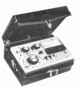
FIGURE 26-2 FIELD-STRENGTH METER. WIDTH IS 9 IN. (BLONDER-TONGUE LABORATORIES
INC.)
All-channel VHF-UHF amplifier. This amplifies the VHF and UHF channel frequencies. A typical unit is shown in Fig. 26-3, with a gain of 40 dB. The input can be one line from a combination antenna or separate lines from VHF and UHF antennas.
Mast-mounted preamplifier. With weak antenna signal, an amplifier may be needed before the main line run from the antenna. Otherwise, • 40 the signal-to-noise ratio will be too low for the main amplifier, causing snow in the picture.
This factor is especially important if the antenna is far from the main amplifier. Remember that a line run of 100 ft could cut the antenna signal voltage by one-half, or 6 dB, depending on the frequency and type of line. A typical gain for the preamplifier is 28 dB. However, the main requirement of the preamplifier is low noise.
Single-channel amplifier. This amplifies the 6-MHz band for any one VHF channel, with a typical gain of 60 dB.
UHF-VHF channel converter. This can be used to convert any one UHF channel to an unused VHF channel. A typical conversion gain is 6 dB. The reason for converting is the lower line losses for the VHF channel frequencies.
Mixer-amplifier. This can be used to combine the signal from several antennas, or from single channel amplifiers, for amplified output to the trunk splitter. A typical gain is 30 dB. Passive antenna mixer. This can combine several antenna signals, but not for adjacent channels. It is passive, without amplification. A typical loss is -2 dB.
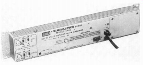
FIGURE 26-3 ALL-CHANNEL AMPLIFIER. (JERROLD ELECTRONICS CORPORATION)
Traps and filters. These passive elements attenuate signals that may cause overload in the amplifier and interference in the picture. They are available for the FM band of 88 to 108 MHz or for an interfering adjacent channel, usually at the sound carrier frequency.
26-2 Distribution of the Signal
In general, a splitter just divides the signal from the main cable to the individual trunk lines. A multitap or single tap off takes a small part of the signal from the trunk line for individual receivers.
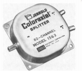
FIGURE 26-4 TWO-WAY SPLITTER. WIDTH IS 3 IN. (JERROLD ELECTRONICS CORPORATION)
FIGURE 26-5 FOUR-WAY MULTITAP WITH COVER OFF. WIDTH IS 4 IN. NOTE ISOLATION RESISTORS.
The tapoff has isolating resistors in order to separate each receiver from the other receivers on the common trunk line. All these components have fittings for coaxial cable, generally with F-type connectors.
Splitters. A two-way splitter divides the signal for two trunk lines; a four-way splitter divides for four trunks. Each division of the signal into two paths means one-half power into each trunk.
This loss is -3 dB, which is 50 percent of the power or 70 percent of the input signal voltage.
A four-way split has double these losses, or -6 dB. Then the result is one-fourth power and 50 percent signal voltage in each trunk line.
A typical splitter is shown in Fig. 26-4.
The splitter is also considered a coupler. Resistance may be included to isolate the output connections from each other and to match the split to the transmission line. When there is less isolation for one outlet, it is a directional coupler.
Tapoffs. A four-way tapoff with isolating resistance in each branch is shown in Fig. 26-5. Each tap can be considered as a series voltage divider. As an example, when 1,12511 is in series with 75 ohm, the total equals 1,200 ohm. The 75 ohm of the cable is then V16 of 1,200 U. Therefore, the tapoff provides 75/ 1.200 == V16 of the trunk signal to a 75-ohm cable. Typically, the fraction of signal tapped off is I/4 to I. The corresponding losses are -12 to -24 dB.
Less signal is usually tapped off at the start of the trunk to allow more signal for receivers at the end of the line. It should be noted that the signal voltage on the trunk is not reduced by the tapoffs because they are parallel paths. Insertion loss reduces the trunk signal.
Wall outlet. This fits into the standard box for an electrical outlet, just to provide a convenient fitting for connecting the distribution line to the television receiver. The wall outlet can be simply a feedthrough connection, without any isolation losses. However, in a layout for single taps the wall outlet itself serves a single tapoff on the trunk, in addition to a feedthrough connection to continue the line to the next tapoff.
Cable termination for the last tap. In general, a tap has connections for the tapoff, plus the input and output lines. The in and out connections are only a continuation of the trunk line. However, the last tap has no place to go on the output side. This end must be terminated with 75 ohm to match the impedance of the line. In Fig. 26-1, each of the trunk lines is terminated with a plug that has the required 75-ohm resistance.
In any distribution system, all the lines must be terminated. An open line is a big source of trouble because it has reflections. These can be coupled into the entire distribution system, causing interference, overload, and ghost problems.
Balun units. A balun matching transformer is generally used to connect the coaxial cable to the antenna. In addition, a balun may be needed at each receiver to connect the 75-ohm cable to the 300-ohm antenna input terminals. However, most sets now have input connections for either coaxial cable or twin lead.
26-3 Types of Distribution Losses
These include the isolation loss at each tapoff, insertion losses in the distribution components, and the attenuation of the cable.
Isolation loss. This is the attenuation caused by isolation resistance. Any tapoff has series resistance to separate each receiver from the trunk line. In the forward direction, from the line to the receiver, the isolation has two effects: (1) matching the impedance of the taps to the impedance of the transmission line, and (2) reducing the amount of signal coupled to the receiver.
In the backward direction, from the receiver to the line, the isolation prevents each receiver from affecting the other receivers on the trunk line. Common problems are oscillator radiation from the receiver and different input impedances. At the receiver end, the impedance may depend on whether the set is on or off and what channel it is operating on.
The isolation loss is present at any tapoff because of the necessary series resistance. This loss applies to multitaps, single taps, and wall outlet tapoffs. Typical losses are -12 to -24 dB, corresponding to voltage ratios of 1/4 to I/,„.
Insertion loss. This includes attenuation of the signal caused by either (1) splitting or (2) I 2R loss in the feedthrough connections. Typically, a two-way splitter has -3 dB loss for the split, plus a feedthrough loss of -0.5 dB for VHF and -1 dB for UHF. The total insertion loss of the splitter, then, is -3.5 dB for VHF or -4 dB for UHF. These insertion losses are twice as great for a four-way splitter.
Cable loss. This is the cumulative effect of I^2R losses in a long line. It can be considered as the insertion loss of the cable. Using low-loss, foam coaxial cable similar to RG-59U, the attenuation can be considered to be 3.2 dB per 100 ft for VHF channel 13 and 6.4 dB for UHF channel 70.
Summary of distribution losses. These are listed in Table 26-1. In general, the isolation loss refers to a tapoff. The insertion losses apply to all distribution components. It should be noted that the isolation loss for a tapoff would normally be counted only once. However, the insertion losses must be added because of their cumulative effect on signal distributed through out the entire system.
TABLE 26-1 TYPES OF DISTRIBUTION LOSSES
26-4 Calculation of Total Losses
The distribution losses are added to find out how much amplifier gain is needed to make up for attenuation of the signal. Note the following points about the general procedure:
1. Take the worst possible case to be sure to have enough signal. Calculate losses for the highest channel to be received. Use the longest line run, if they are not all the same.
2. It is only necessary to calculate the losses for one trunk line. If there is signal for the longest trunk, all the lines will have enough signal.
The procedure involves supplying at least 1-mV signal for the last receiver on the trunk line.
The distribution losses can be grouped in three categories: cable loss, insertion loss, and isolation loss. Insertion losses are added throughout the trunk-line distribution. The isolation loss is just at the tapoff for each receiver. Specific examples will be calculated now for the distribution with four-way tapoffs in Fig. 26-1 and the commonly used method with single tapoffs, which is illustrated in Fig. 26-6.
26-5 System with Multitaps
Refer to the distribution in Fig. 26-1. The cable length for each trunk is 30 ft + 30 ft + 40 ft from the two-way splitter. No length is added for the wall outlets because we assume they are close to the multitaps. The total cable length, then, is 100 ft. We can use foam RG-59U, which has a loss of -6.4 dB for the UHF channels. All the losses here are for a VHF-UHF system.
The insertion loss for the splitter can be taken as -4 dB for UHF. It includes -3 dB for the two-way split and -1 dB for the feedthrough loss. The splitter may have isolation between the outputs, but this is not considered as a series tapoff loss.
The four-way multitap has an insertion loss of -1.5 dB for UHF. This loss is for the whole unit, from the input to output connections. However, the loss of the last unit on the trunk is not added because this signal does not feed through. In Fig. 26-1, therefore, the total insertion loss of the multitaps is 2 x -1.5 = -3 dB for each trunk line.
Each tap can be assumed to have an average isolation loss of -18 dB. This value is counted only once because the loss is in the line to each receiver. Tabulating the losses: Attenuation of 100 ft of cable Insertion loss for two-way splitter Insertion loss for two multitaps Isolation loss of each tapoff
= - 6.4 dB
- 4.0 dB
- 3.0 dB
- 18.0 dB
Total loss of trunk line = - 31.4 dB
This distribution loss can be made up by a VHF-UHF amplifier with a gain of 30 to 40 dB. The 40 dB corresponds to a voltage gain of 100. Typically, the amplifier can take antenna signal of 2 mV and supply output of 200 mV for the splitter. This output signal is divided by one-half for approximately 100 mV to the two trunk lines.
Then there is enough signal on both trunks for all the tapoffs on the line.
26-6 System with Single Taps at Wall Outlets
Refer to the distribution in Fig. 26-6. The losses in this layout are calculated for each of the four trunks. Each line has a length of 70 + 30 = 100 ft. The calculations are for VHF only, assuming that any UHF channels will be converted to VHF. There are seven tapoffs, plus one termination, for each trunk. The tabulation is:
Attenuation of 100 ft of foam cable, RG-59U, at VHF = -
Insertion loss for four-way splitter = -
Insertion loss for seven tapoffs (7 x 0.75)
Isolation loss of each tapoff
3.2 dB
7.0 dB
= 5.25 dB
= - 18.0 dB
Total loss of trunk line = - 33.45 dB
FIGURE 26-6 CABLE DISTRIBUTION SYSTEM FOR 32 RECEIVERS, SPLITTER AND SINGLE TAPOFFS,
This distribution loss of approximately -34 dB can be made up by an amplifier that has a voltage gain of 50 or 34 dB. With 2 mV into the amplifier, the output signal is 100 mV. This is divided into a little less than 25 mV for each of the four trunks. Then each trunk has enough signal for the tapoffs (Fig. 26-7). The tapoffs near the splitter should have minimum insertion loss to feed through enough signal for the end of the line. Also, these tapoffs at the start of the cable could have a little more isolation loss than the average, taken as-18 dB, while those near the end of the cable would have less isolation loss. Remember that the signal level becomes smaller at the end of the trunk because of cable attenuation and insertion losses.
The differences in isolation losses could progress in steps of -2 dB, which is the approximate attenuation between two tapoffs. This is done to equalize the signal strength for all receivers on the trunk line. Adjustable tapoffs are available to vary the isolation loss from -10 USING FOUR-WAY to -20 dB, corresponding to a tapoff of one third to one tenth of the signal on the cable.
26-7 Decibel (dB) Units
The decibel (dB) unit is a logarithmic ratio that is convenient in calculating gains and losses for power, voltage, or current. The reason is that dB values are added or subtracted, not multiplied or divided. The logarithmic factor also compresses a wide range of values into smaller numbers.
Originally, the bet unit was defined for audio work as log (P2/ P1 ). The logarithm is to base 10.
P2/P1 is the ratio of two values of power. Either IF or rf signals can be compared.
The logarithmic unit generally used is the decibel, equal to one-tenth of a bel. The value of 1 dB indicates a gain or loss of approximately 26 percent in power or 12 percent in voltage. This much change in audio signal is just perceptible to the ear.
FIGURE 26-7 COMBINATION WALL OUTLET AND SINGLE TAPOFF (JERROLD ELECTRONICS
CORPORATION)
Power ratios. The formula for calculating the dB comparison between two values of power is
dB = 10 x log (P2/P1) (26-1)
To calculate dB values with this formula, the following method can be used:
1. Find the numerical ratio of the two powers.
Be sure to use the same units for both. For instance, if P, is 1 W and P, equals 1 mW, this ratio is 1,000 mW/1 mW = 1,000.
2. Always let P2 in the numerator be the larger number. Then the ratio must be 1 or more.
This eliminates the problem of working with fractions less than 1, which have a negative logarithm.
3. Find the logarithm of the power ratio. Here, 1,000, or 103, has the logarithm 3.
4. Multiply the logarithm by 10 to calculate the answer in decibels. Here we have 10 x 3 = 30 dB. This answer is +30 dB for a gain from 1 mW to 1,000 mW. For a decrease from 1,000 mW to 1 mW the loss would be -30 dB. The dB value is the same for an equal gain or loss. Also, the power ratio is independent of the impedances that develop the powers.
Voltage ratios. Since power is E^2/R or I^2R, the decibel formula can also be expressed in terms of voltage and current. The dB formula is often used for voltages as: dB = 20 x log HE ) E, (26-2)
The two voltages E, and E, must be across the same value of impedance. If they are not, multi ply Eq. (26-2) by the correction factor \ . For example, for a gain from 1 mV to 1,000 mV across the same value of Z, the dB voltage gain is dB = 20 x log ( ) dB = 20 x log (1,000) = 20 x 3 = 60
The 60-dB gain for a voltage ratio of 1,000 is double the dB gain for a power ratio of 1,000 because the voltage formula has the multiplying factor of 20 instead of 10. The reason is that power is proportional to the square of voltage.
In logarithms, squaring a number corresponds to doubling its logarithm. Therefore, a voltage ratio always equals twice the decibels of the same numerical power ratio.

TABLE 26-2 COMMON DECIBEL VALUES
Reference levels. In order to make the dB units more useful, standard values are used for comparison. Then only one value of P or E compared with the reference can be specified by a decibel value. There are several references in common use, but you can tell which is being used by the abbreviation: dB = 6 mW across 500 ohm as the reference.
dBm = 1 mW across 600 II as the reference.
dBmV = 1 mV across 75 -ohm.
This reference is used for cable television because we are interested in the amount of signal voltage for coaxial cable with a nominal impedance of 75 Ohm. As a formula, the dBmV reference can be stated:
dBmV = 20 x log ( E2 1 mV (26-3)
For an rf signal voltage of 100 mV, as an example, this voltage ratio is 100 or 102 compared with the reference of 1 mV. The log of 100 is 2. Then
/100 mV dBmV = 20 x log 1 1 mV dBmV = 20 x 2 = 40
When using reference levels, it is important to note that 0 dB indicates the value equal to the reference. The reason is that the log of 1 happens to be zero. As an example, assume a voltage of 1 mV as the value compared with the dBmV reference:
1 mV dBmV = 20 log 1 mV
= 20 x log 1
= 20 x 0 = 0
In all cases of decibel comparisons, the 0 dB means equal values are being compared, with a ratio of unity.
Adding and subtracting dB values. Adding the logarithms of numbers corresponds to multiplying the numbers. Also, subtracting logarithms corresponds to dividing numbers. Therefore, dB values in cascade are added or subtracted. For instance, two amplifiers in cascade, each with a dB gain of 13, provide a total gain of 26 dB. As another example, when signal voltage at a level of 20 dBmV is fed into a line with an attenuation of -9 dBmV, the signal level at the end of the line is 20 - 9 = 11 dBmV. Common decibel values. The ratios listed in Table 26-2 are worth memorizing because they can be used as short-cuts in dB calculations. A1 though shown as +dB for gain, the same ratios inverted apply for -dB with losses.
Consider some voltage ratios for dBmV with the reference of 1 mV. Double this value is 6 dBmV, or 2 mV. One-half the reference voltage is -6 dBmV, or 0.5 mV. Ten times the reference is 20 dBmV or 10 mV, because the log of 10 is 1.
Then 20 x 1 = 20 dBmV. Also, 100 mV is 40 dBmV because the log of 100 is 2. Then 20 x 2 = 40 dBmV. Doubling the voltage ratio always adds 6 dB. Not only is 6 dB two times the voltage, but 12dB is four times, 18dB is eight times, 24 dB is 16 times, and 48 dB is 256 times the voltage, as examples. Each addition of 6 dB means doubling of the voltage. It should also be noted that 10 dBmV is approximately three times the voltage. See Table 26-2.
A useful technique is dividing the ratio into factors that are easier to convert to decibels and then adding the dB values. For instance, a voltage ratio of 200 is the same as 100 x 2. The factor of 100 equals 40 dB, while double the voltage is 6 dB. Therefore, the factors of 100 x 2 yield the values of 40 dB + 6 dB = 46 dB for the voltage ratio of 200. With the 1 mV reference, this equals 200 mV for 46 dBmV.
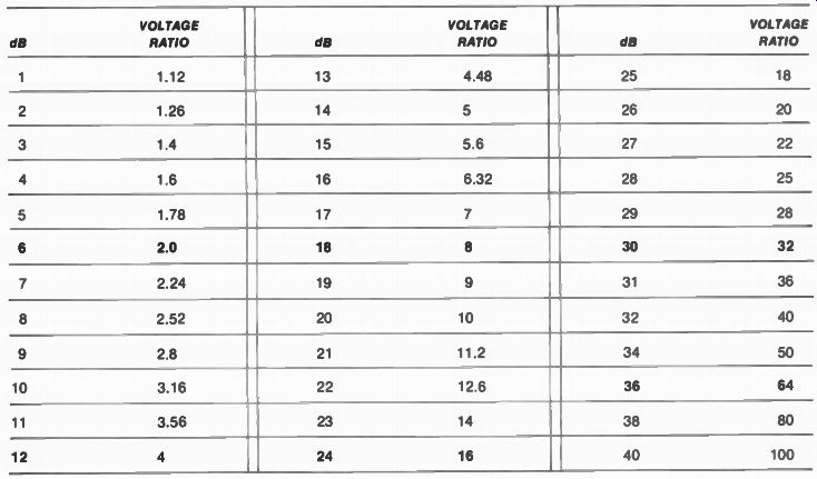
TABLE 26-3 DECIBELS (dB) AND VOLTAGE RATIOS --- Calculated as dB = 20 log(V,/V, with both voltages across the same impedance.
26-8 Decibel Conversion Charts
Tables 26-3 and 26-4 list the dB values for different voltage ratios, to eliminate the need to use the decibel formula with logarithms. Table 26-3 is in a general form for comparison of two voltages without any reference. However, the values in Table 26-4 are specifically for the dBmV reference of 1,000 V or 1 mV. Note that starting with 6 dB for a voltage ratio of 2, each increase of 6 dB shows a doubled voltage ratio. These values are in bold face type. Any doubled voltage ratio is 6 dB higher.
The last four values in the table are in multiples of 2 dB in order to complete the list with 40 dB for a voltage ratio of 100. For a larger voltage ratio, divide it into factors and add the dB values for the factors. As an example, a voltage ratio of 10,000 is 100 x 100. This corresponds to 40 dB + 40 dB = 80 dB. For the opposite conversion with more than 40 dB, separate it into terms that can be added to give the total dB value, and then multi ply the corresponding voltage ratios. As an example, 46 dB = 40 dB + 6 dB. The voltage ratios are 100 for 40 dB and 2 for 6 dB. Then multiply 100 x 2 = 200 to get the voltage ratio for 46 dB. In Table 26-4, note that 1 mV= 1,000 AV, which is the reference value for 0 dBmV. Values less than 1,000 uV correspond to -dBmV; voltages more than 1,000 µV are +dBmV. The voltage ratios are approximate values, having been rounded off to fit the pattern of 6 dB more for double voltage and 6 dB less for one-half voltage.
TABLE 26-4 MICROVOLTS AND dBmV*
Calculated as dBmV = 20 log(E2 /1 mV) across 75-ohm impedance.
SUMMARY
The following definitions, in alphabetical order, summarize the terminology of cable distribution systems.
Amplifier. A device which increases signal level by 20 to 55 dB. Types include VHF, UHF, combined UHF-VHF, and single-channel amplifiers.
Attenuator. A device which reduces signal level.
Balun. A device which matches 300-ohm balanced and 75-ohm unbalanced impedances.
Also called an elevator transformer.
Booster. A small preamplifier for antenna signal.
Cable equalizer. A device which compensates for tilt in cable attenuation from channel 2 to channel 13, for very long lines.
Cable losses. Attenuation of the distribution line.
CATV. Cable television. This abbreviation is generally used for systems that serve many receivers in individual homes.
CCTV. Closed-circuit television. Distribution by cable to selected receivers, but usually for video signal rather than antenna rf signal.
Characteristic impedance (Z(). A property of a cable independent of length. Z„ is nominally 75 it for coaxial cable and 300 ohm for twin lead.
Converter. A device which converts a UHF channel to a VHF channel for lower losses in cable distribution.
dB. Abbreviation for decibel. The dBmV unit is compared with the reference of 1 mV. Elevator transformer. Same as balun, to match between 75-ohm unbalanced and 300-ohm balanced impedances.
ETV. Educational television for schools, often using a cable distribution system.
Filter. A device which passes the desired band but attenuates other frequencies.
FSM. Abbreviation for field-strength meter, a device which measures signal at the antenna location.
Head end. A section which includes the antenna, amplifier, and any additional equipment needed to feed signal into the cable distribution system.
Impedance matching. Terminating a line in its characteristic impedance.
Insertion loss. Attenuation in the series path of the signal. This loss is cumulative in the trunk line.
Isolation. Separation between signal paths, usually by series resistance in each of the parallel branches. This loss is mainly in the tapoff for each receiver.
MA N. Master antenna television. Feeding multiple receivers from a master antenna, as in motels and apartment buildings.
Mixer. A device which combines signals from several antennas.
Pad. A fixed attenuation, usually with resistors.
Passive component. A device which has no amplification -no tubes or transistors.
Preamplifier. A low-noise amplifier for boosting the antenna signal before the main amplifier.
Splitter. A device which divides signal from one line into two or more lines.
Standard signal. For cable television, 1 mV across 75 ohm for each receiver. This level is 0 dBmV. Tapoff. A voltage divider to take part of the cable signal to each receiver.
Terminating plug. A 75-ohm resistor to terminate the end of a trunk cable in its characteristic impedance.
Tilt. Unequal cable attenuation for different channels.
Trap. A device which attenuates a specific frequency.
Trunk. A line from the splitter to tapoffs for the receivers.
Wall outlet. A connection between the cable and the receiver without isolation resistance.
Wall tapoff. A connection between the cable and the receiver with isolation resistance. It also feeds signal through to the next tapoff.
Self-Examination (Answers at back of guide)
1. Typical gain of an amplifier for the VHF channels is: (a) 0 dB; (b) -5 dB; (c) 2 dB; (d) 40 dB.
2. Which of the following lines has the greatest losses: (a) twin lead; (b) open-wire; (c) RG-59U coaxial cable; (d) foam RG-11U coaxial cable.
3. The standard signal voltage used as the reference for the dBmV unit is: (a) 6 mV in 500 ohm; (b) 1 mV in 75 ohm; (c) 1 mW in 600 ohm; (d) 6 mW in 1 ohm.
4. The loss in a 2-for-1 split is approximately: (a) 3 dB; (b) 8 dB; (c) one-third voltage; (d) one-quarter power.
5. A tapoff with an isolation loss of -20 dB takes the following fraction of signal voltage: (a) one-half; (b) one-fourth; (c) one-tenth; (d) one-hundredth.
6. The number of trunk lines in Fig. 26-1 is: (a) 1; (b) 2; (c) 3; (d) 4.
7. The number of wall-outlet tapoffs on each trunk line in Fig. 26-6 is: (a) 4; (b) 6; (c) 7; (d) 8.
8. The terminating resistance at the end of a trunk line is: (a) 75 ohm; (b) 100 ohm; (c) 150 ohm; (d) 300 ohm.
9. The number of insertion losses added for the wall-outlet tapoffs in Fig. 26-6 equals: (a) 7; (b) 8; (c) 16; (d) 31.
10. The minimum signal required for each receiver in the distribution system is approximately: (a) 0 mV; (b) 1 mV; (c) 6 mV; (d) 10,000 µV.
Essay Questions
1. Give three types of amplifiers for the antenna signal.
2. What is the difference between a split and a tapoff?
3. Why is coaxial cable used for distribution systems?
4. What is the advantage of converting a UHF channel to a VHF channel for the distribution system?
5. What is the function of a mast-mounted preamplifier?
6. Give the function of the following: balun, U/V splitter, FM trap, and terminating plug.
7. What is the difference between a four-way splitter and a four-way multitap?
8. For an average isolation loss for a tapoff on the trunk line, give the dB value and the corresponding fraction of signal voltage tapped off the line.
9. List the three main types of losses in a distribution system.
10. Show the layout for 40 receivers and calculate typical losses for the VHF television channels. Use a four-way splitter with four trunk lines and single wall-outlet tapoffs, as in Fig. 26-6.
Problems (Answers to selected problems at back of guide)
1. Give the dB values for the following voltage ratios: (a) 2:1; (b) 3:1; (c) 10:1; (d) 20:1; (e) 100:1.
2. Give the voltage ratios for the following dB values: (a) 6 dB; (b) 10 dB; (c) 20 dB; (d) 26 dB; (e) 40 dB.
3. Give the mV values for the following dBmV levels: (a) 0 dBmV; (b) 6 dBmV; (c) 10 dBmV; (d) 20 dBmV; (e) 40 dBmV; (f) 46 dBmV.
4. Give the dBmV levels for the following signal voltages: (a) 1 mV; (b) 2 mV; (c) 3 mV; (d) 10 mV; (e) 100 mV; (f) 200 mV.
5. Calculate the net dB gain for -4 dB loss, 50 dB gain, -7 dB loss, and -24 dB loss.
6. Calculate the signal level for 80 dBmV.
7. Calculate the dBmV level for a signal of 2V.
8. An antenna signal of 100 AV has a gain of 20 dB, loss of -6 dB, gain of 40 dB, and loss of -34 dB. Calculate the output signal level in millivolts.