The method of transmitting the amplitude-modulated (AM) picture signal is
similar to the more familiar system of AM radio broadcasting. In both cases,
the amplitude of an rf carrier wave is made to vary with the modulating voltage.
Modulation is necessary so that each broadcast station can have its own rf
carrier frequency. Then the rf section of the receiver can be tuned to different
stations. In television broadcasting, the composite video signal modulates
a higher-frequency carrier wave to produce the AM picture signal* illustrated
in Fig. 6-1. The amplitudes in the transmitted carrier wave vary with the
video modulating signal. More details of the AM picture signal are explained
in the following topics:
6-1 Negative transmission
6-2 Vestigial-sideband transmission
6-3 Television broadcast channels
6-4 The standard channel
6-5 Line-of-sight transmission
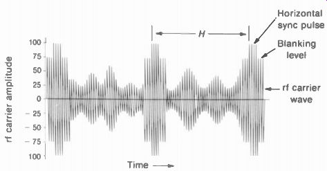
FIGURE 6-1 TRANSMITTED PICTURE CARRIER WAVE. AMPLITUDE-MODULA TED BY COMPOSITE
VIDEO SIGNAL
The term "picture signal" is used here for the modulated rf carrier wave, while "video" represents the signal that can be used directly to reproduce the desired visual information when applied to a picture tube, corresponding to "audio" in a sound system.
6-1 Negative Transmission
The transmitted picture carrier signal in Fig. 6-1 is shown with the negative polarity of modulation that is an FCC standard. Negative transmission means that changes toward white in the picture decrease the amplitude of the AM picture carrier signal.
In Fig. 6-1 the tips of sync voltage produce the peaks of rf amplitude in the AM carrier wave.
This peak carrier amplitude is its 100 percent level. The blanking level in the composite video signal is transmitted at a constant level of 75 percent of peak carrier amplitude. Smaller amplitudes in the modulated rf carrier correspond to picture information that varies between black and maximum white. The whitest parts of the picture produce a carrier amplitude 10 to 15 percent of the peak value. All these relative amplitudes are the same for the top or bottom of the envelope because the modulated rf carrier wave has a symmetrical envelope of amplitude variations.
The negative transmission refers to the polarity of video modulating voltage, not individual cycles of the rf carrier, both being positive and negative. The result of white video signal amplitudes having negative polarity at the grid of the modulator is negative polarity of modulation. Then the carrier amplitude decreases for white video modulating voltage. If the video modulating signal had opposite polarity, the transmitted carrier would have positive polarity of transmission.
An advantage of negative transmission is that noise pulses in the transmitted rf signal increase the carrier amplitude toward black, which makes noise less obvious in the picture.
Also, the transmitter uses less power with lower carrier amplitudes for pictures that are mostly white.
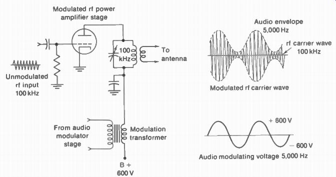
FIGURE 6-2 PLATE-MODULATION CIRCUIT. THE 100-kHz RF CARRIER IS AMPLITUDE
MODULATED BY THE 5,000-Hz AUDIO VOLTAGE.
-------------------
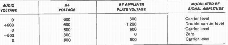
TABLE 6-1 MODULATION VALUES FOR FIG. 6-2
AUDIO VOLTAGE
B+ VOLTAGE
RF AMPLIFIER PLATE VOLTAGE 600
MODULATED RF SIGNAL AMPLITUDE
Carrier level
Double carrier level
Carrier level Zero
Carrier level
------------------------
6-2 Vestigial-Sideband Transmission
The AM picture signal is not transmitted as a normal double-sideband signal. Instead, some of the sideband frequencies are filtered out before transmission in order to reduce the bandwidth of the channel needed for the modulated picture signal. To see how this vestigial sideband transmission is accomplished, we can consider first the idea of how amplitude modulation produces sideband frequencies.
Amplitude modulation. In Fig. 6-2 an rf carrier wave is amplitude-modulated by a sine-wave audio signal in a plate-modulation arrangement.
For simplicity the rf carrier frequency is taken as 100 kHz and the audio as 5,000 Hz. The B+ voltage for the rf power amplifier is assumed to be 600 V, and the peak value of the audio sine-wave modulating voltage is also 600 V. allowing 100 percent modulation.
Note that the audio voltage across the secondary of the modulation transformer is in series with the 8+ supply and the rf amplifier plate circuit. Therefore, the audio modulating voltage varies the plate voltage of the rf amplifier at the audio rate (see Table 6-1). The varying amplitudes of the rf carrier wave provide an envelope that corresponds to the audio modulating voltage. Both the positive and negative peaks of the rf carrier wave are symmetrical above and below the center axis and have exactly the same amplitude variations.
The envelope is symmetrical because the changes in amplitude of the negative and positive half cycles of the rf signal are equal, as the carrier amplitude is varied at the audio rate, which is much slower than the rf variations. Any point on the audio waveform includes many cycles of the rf carrier. The result of the modulation in this case, is to produce an rf carrier wave at a frequency of 100 kHz with an amplitude that varies at the audio rate of 5,000 Hz. Either the top or bottom envelope of the amplitude modulated carrier wave corresponds to the 5,000-Hz audio modulating signal.
Side-carrier frequencies. Referring now to Fig. 6-3, the AM wave is shown to be equal to the sum of the unmodulated rf carrier and two side carrier frequencies. Notice that the carrier and its equivalent side frequencies all have a constant level. Also, the amplitude of the side carriers equals one-half the unmodulated carrier level, for 100 percent modulation. Each side frequency differs from the carrier by the audio modulating frequency. The upper side frequency is 105 kHz, and the lower side frequency 95 kHz in this illustration.
The question as to whether the transmit ted signal is a carrier with varying amplitudes or a constant-amplitude carrier with its two side carriers is without meaning, because the two concepts are the same. The constant-level side carriers plus the unmodulated carrier wave are equal to the AM carrier signal. Or, the AM carrier wave is equal to the unmodulated carrier plus two side carriers of proper amplitude, phase, and frequency. The equivalence of the two signals is due to the fact that the modulated rf carrier wave is distorted slightly from true sine wave form by the audio amplitude variations, producing new frequency components, which are the side frequencies.
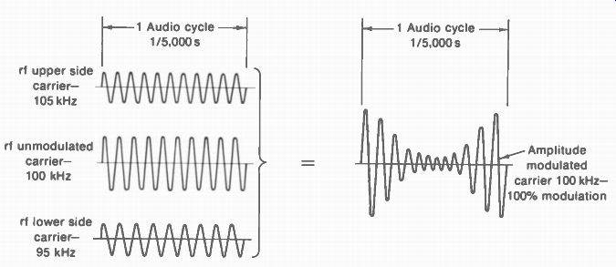
FIGURE 6-3 EQUIVALENCE OF AM WAVE TO THE CARRIER PLUS TWO RF SIDE CARRIERS
PRODUCED BY MODULATION.
The envelope is not a side frequency. The rf side-carrier frequencies should not be confused with the audio envelope. The envelope is an audio frequency. The side carriers are radio frequencies close to the carrier frequency. For the case here, the envelope is the audio modulating signal of 5,000 Hz, while the rf side frequencies are 105 and 95 kHz. If the audio modulating frequency is 1,000 Hz. the rf side frequencies will be 101 and 99 kHz. Then the modulated carrier will have an audio envelope of 1,000 Hz.
Side bands. When the carrier is modulated by a voltage that includes many frequency components, each audio modulating frequency produces a pair of rf side frequencies. In each pair, one side frequency is higher than the carrier frequency and one is lower. All the higher side frequencies can be considered as the upper side band of the carrier with all the lower side frequencies the lower side band. This idea is illustrated in Fig. 6-4 for the case of modulation with a continuous band of audio frequencies from 0 to 5,000 Hz. The graph here indicates the corresponding side frequencies for a 100-kHz carrier. The upper side band includes all side frequencies from the carrier frequency of 100 up to 105 kHz: the lower side band includes the side frequencies down to 95 kHz. The bandwidth required for the two side bands in this case is 15 kHz centered around the carrier frequency of 100 kHz, or a total bandwidth of 10 kHz. Note that the required bandwidth for the AM carrier with two side bands is double the highest modulating frequency.
The fact that different audio modulating frequencies produce different side frequencies in AM should not make it be confused with frequency modulation. In FM the rf carrier frequency varies in accordance with the amount of audio modulating voltage, but in AM the side frequencies depend on the audio modulating frequency.
The baseband. This is the band of modulating frequencies for either AM or FM. In this example of audio modulating frequencies up to 5,000 Hz, the baseband is 0 to 5 kHz. In television broad casting the baseband is 50 to 15,000 Hz for the FM sound signal and 0 to 4 MHz, approximately, for the AM picture signal.
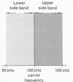
FIGURE 6-4 DOUBLE SIDE BANDS RESULTING FROM AM PLITUDE MODULATION OF 100-kHz
CARRIER WITH ALL MODULATING FREQUENCIES UP TO 5 kHz
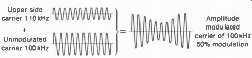
FIGURE 6-5 EQUIVALENCE OF CARRIER AND ONE SIDE CARRIER TO AM WAVE.
Vestigial side bands. Note that the information of the modulating signal is in the side bands of the amplitude-modulated rf carrier. Frequency of the modulation is indicated by how much the side frequencies differ from the carrier frequency; modulating voltage is indicated by the amplitude of the two side carriers. For the case of 100 percent modulation, each side carrier has one-half the unmodulated carrier amplitude. Furthermore, the upper and lower side frequencies have the same information, since they are of equal amplitude and each differs from the carrier frequency by the same amount. The desired modulating signal can be transmitted by one side band. therefore, and it does not matter whether the upper or lower side band is used. With only one side band, the transmitted signal has the advantage of only one-half the bandwidth of two side bands. The amplitude modulation normally produces double side bands, but one side band can be filtered out if desired.
Figure 6-5 illustrates just one side frequency transmitted with the carrier. Notice that the resultant modulated wave has amplitude variations for only 50 percent modulation, in stead of the 100 percent modulation produced with both side bands. In Fig. 6-5, the modulated wave varies in amplitude 50 percent above and below the unmodulated carrier amplitude, but with 100 percent modulation the peak carrier amplitude doubles the unmodulated level and decreases to zero. Therefore, a signal transmit ted with one side band has effectively one-half the percent modulation, compared with double sideband transmission. The same reduction factor of /2 applies when the varying modulating voltage produces different amounts of modulation less than 100 percent.
Except for the amount of amplitude swing, the envelope of the carrier plus one side band can be considered essentially the same as with double-sideband transmission, although there is slight distortion for high percentages of modulation. Notice that the envelope in Fig. 6-5 still corresponds to the audio modulating voltage. Furthermore, the envelope is not cut off at the top or bottom of the AM wave. Remember that one rf side frequency is filtered out, but not the audio envelope. In order to remove one part of the envelope it would be necessary to rectify the modulated carrier signal.
The method just described can be considered single-sideband transmission with the carrier. In many applications of single-sideband transmission, however, the carrier itself is not transmitted in order to save power by suppressing the carrier. Then only one side band is trans mitted. In this situation, the carrier must be reinserted at the receiver to detect the signal.
A compromise between double-sideband transmission and the single-sideband method is used for broadcasting the AM picture carrier signal. In this system, called vestigial-sideband transmission, all of one side band is transmitted but only a part, or vestige, of the other side band.
The picture carrier itself is transmitted. More specifically, all the upper side band of the AM picture signal is transmitted, to include all video modulating frequencies up to 4 MHz. The lower side band, however, includes only video modulating frequencies up to 0.75 MHz approximately, to conserve bandwidth in the broadcast channel. The vestigial-sideband transmission used in television is designated by the FCC as emission type A5C.
6-3 Television Broadcast Channels
Each television broadcast station is assigned a 6-MHz channel for transmission of the AM picture signal and the FM sound signal. Vestigial sideband transmission is used for the picture signal, so that video modulation frequencies up to 4 MHz can be broadcast in the 6-MHz channel.
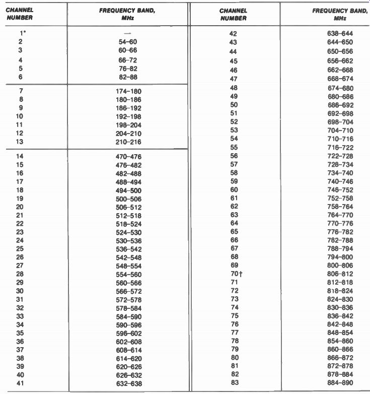
TABLE 6-2 TELEVISION CHANNEL ALLOCATIONS ---- 'The 44- to 50-MHz band was
television channel 1 but is now assigned to other services.
Channels 70 to 83 are also allocated for land mobile radio services. For television, these UHF channels are used mainly by translator stations (see Sec. 6-5).
Assigned channels. Since the picture carrier frequency must be much higher than the highest video modulating frequency of 4 MHz, the television channels are assigned in the VHF band of 30 to 300 MHz and the UHF band of 300 to 3,000 Mhz. Table 6-2 lists the channels and frequencies assigned by the FCC for commercial television broadcast stations in the United States.
The television channel frequencies can be considered in three groups: the five low-band channels 2 to 6 in the VHF range, seven high-band channels 7 to 13 also in the VHF range, and the 70 UHF channels 14 to 83. Frequencies between these television broadcasting bands are used by other radio services.
The number of channels available for television broadcast stations in any one locality depends upon its population, varying from one channel in a smaller city to twelve stations for New York City, including VHF and UHF channels. Most cities have at least one channel reserved for a noncommercial educational television broadcast station.
One channel can be used by many broad cast stations, but they must be far enough apart to minimize interference between them. Such stations using the same channel are co-channel stations. They must be separated by 170 to 220 mi for VHF channels or 155 to 205 mi for UHF channels. Stations that use channels adjacent in frequency, like channels 3 and 4, are adjacent-channel stations. To minimize interference between them, adjacent-channel stations are separated by 60 mi for VHF channels or 55 mi for UHF channels. However, channels consecutive in number but not adjacent in frequencies, such as channels 4 and 5, channels 6 and 7, or channels 13 and 14, can be assigned in one area.
6-4 The Standard Channel
The structure of a standard television channel is illustrated in Fig. 6-6a. The width of the channel is 6 MHz, including the picture and sound carriers with their sideband frequencies. The picture carrier is spaced 1.25 MHz from the lower edge of the channel, and the sound carrier is 0.25 MHz below the upper edge of the channel. As a result, there is always a fixed spacing of 4.5 MHz between the picture and sound carrier frequencies. The specific picture and sound carrier frequencies for all television broadcast channels are listed in Appendix A.
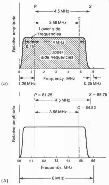
FIGURE 6-6 THE STANDARD TELEVISION BROADCAST CHANNEL. P IS PICTURE CARRIER.
S IS SOUND CARRIER. AND C IS COLOR SUBCARRIER. (a) FREQUENCY SEPARATIONS FOR
ANY CHANNEL. lb) SPECIFIC FREQUENCIES FOR CHANNEL 3, 60 TO 66 MHz.
The standard channel characteristics shown in Fig. 6-6 should not be interpreted as an illustration of the picture signal. The graph merely defines the signal frequencies that can be transmitted in the television channel, with their relative amplitudes. The picture carrier is shown with twice the amplitude of the sideband frequencies, which are their relative amplitudes for 100 percent modulation.
Since the sound signal is frequency modulated, its sideband frequencies do not have the same type of amplitude characteristic as in the picture signal, and these are not shown. The sound carrier signal is a conventional FM signal, with a bandwidth of approximately 50 kHz for a frequency swing of ± - 25kHz with 100 percent modulation.
In the picture signal, all upper sideband frequencies up to approximately 4-MHz video modulation are transmitted with their normal amplitude. The color subcarrier at 3.58 MHz can be considered as just another high video frequency signal that modulates the picture carrier with the desired color information. For monochrome information, the high video frequencies represent only edge details. For a color program, however, 3.58 MHz represents the color signal needed for all the color information.
The lower side-carrier frequencies that differ from the picture carrier by more than 0.75 MHz but less than 1.25 MHz are gradually attenuated. Lower side-carrier frequencies below the picture carrier by 1.25 MHz or more are out side the channel. These frequencies must be completely filtered out at the transmitter so that they will not be radiated to interfere with the lower adjacent channel. Note that upper side carrier frequencies more than 4 MHz above the picture carrier frequency are also attenuated to eliminate interference with the associated sound signal.
Examples of rf channel frequencies. Numerical values for channel 3 as a typical television channel are shown in Fig. 6-6b. The channel has a bandwidth of 6 MHz, from 60 to 66 MHz.
The picture carrier is 1.25 MHz above the lower edge of the channel, which is 61.25 MHz for this channel. The sound carrier at 65.75 MHz is 4.5MHz above the picture carrier frequency.
With vestigial-sideband transmission, all the upper sideband frequencies up to 65.25 MHz are transmitted. However, only that part of the lower sideband frequencies down to 60.5 MHz, approximately, is transmitted without attenuation. As an example, when the video modulating voltage has a frequency of 0.75 MHz, both the upper and lower side frequencies of 62 and 60.5 MHz are transmitted. For this case, the picture carrier is a normal double-sideband signal. The same is true for any video modulating signal having a frequency less than 0.75 MHz.
However, for components of video modulating signal with a frequency higher than 0.75 MHz, only the upper side carrier is transmitted with normal amplitude. For 2-MHz video modulation, as an example, the upper side frequency of 63.25 MHz is in the channel. The lower side frequency is 59.25 MHz, which is outside channel 3 and must be filtered out at the transmitter.
In this case, then, only the upper side frequency is transmitted with the picture carrier, resulting in single-sideband transmission. The result is a vestigial-sideband transmission system because double-sideband transmission is used for video modulating frequencies lower than 0.75 MHz, but single-sideband transmission is used for higher video modulating frequencies up to 4 MHz, approximately.
The color video signal of 3.58 MHz is at 64.83 MHz as an upper side frequency of the modulated picture carrier in channel 3. This frequency is calculated as 61.25 + 3.58 = 64.83 MHz. If the receiver does not pass 64.83 MHz in the antenna and rf circuits for channel 3, there will be no color.
Advantage of vestigial-sideband transmission. This advantage can be seen from the fact that the picture carrier is 1.25 MHz from the end of the channel, allowing video modulating frequencies up to 4 MHz to be transmitted in the 6-MHz channel. A video-frequency limit of about 2.5 MHz would be necessary if double sideband transmission were used with the picture carrier at the center of the channel. This would represent a serious loss in horizontal de tail, since the high-frequency components of the video modulation determine the amount of horizontal detail in the picture.
It might seem desirable to place the picture carrier at the lower edge of the channel and use single-sideband transmission completely.
This method would allow the use of video modulating frequencies higher than 5 MHz and increased horizontal detail. However, this is not practicable. The elimination of undesired side carrier frequencies is accomplished by a filter circuit at the transmitter, which cannot have ideal cutoff characteristics. Therefore, it would not be possible to remove side carriers that are too close to the carrier frequency without introducing objectionable phase distortion for the lower video signal frequencies, which causes smear in the picture. The low video frequencies have the most important information for the picture.
The practical compromise of vestigial sideband transmission that is used provides for complete removal of the lower side band only where the side-carrier frequencies are sufficiently removed from the picture carrier to avoid phase distortion. The picture carrier itself and the side frequencies close to the carrier are not attenuated. The net result is normal double sideband transmission for the lower video frequencies corresponding to the main body of picture information for large areas in the picture.
The single-sideband transmission is used only for the higher video frequencies that represent details of edges or outlines in the picture Compensating for the vestigial-sideband trans mission. It should be noted that the picture signal is distorted in terms of relative amplitude for different frequencies. Remember that a signal transmitted with only a single side band and the carrier represents 50 percent modulation in comparison with a normal double-sideband signal with 100 percent modulation. Therefore, the higher video frequencies provide signals with one-half the effective carrier modulation, compared with the lower video frequencies that are transmitted with both side bands. This is in effect a low-frequency boost in the video signal.
However, it is corrected by deemphasizing the low video frequencies to the same extent in the IF amplifier of the television receiver.
6-5 Line-of-Sight Transmission
Propagation of radio waves in the VHF and UHF bands is produced mainly by ground-wave effects, rather than sky waves from the ionized atmosphere. The ground wave is that part of the radiated signal affected by the presence of the earth, and it can be considered as being propagated along the surface of the earth from the transmitting antenna. Since the television broadcast channels are in the VHF and UHF bands, transmission of the picture and sound carrier signals is determined primarily by ground-wave propagation.
Horizon distance. The transmission distance that can be obtained for the ground-wave signal is limited by the distance along the surface of the earth to the horizon, as viewed from the transmitting antenna. This is called line-of-sight transmission; the line-of-sight distance to the horizon is the horizon distance (see Fig. 6-7). The horizon distance for the transmitted radio wave, however, is about 15 percent longer than the optical horizon distance because the path of the ground wave curves slightly in the same direction as the earth's curvature. This bending of the radio waves by the earth's atmosphere is called refraction. The graph in Fig. 6-8 shows the radio horizon distance directly for any antenna height up to 10,000 ft.
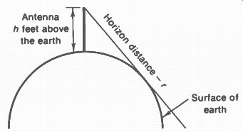
FIGURE 6-7 HORIZON DISTANCE r DEPENDS ON ANTENNA HEIGHT h.
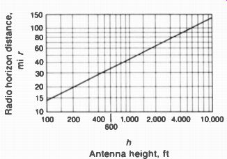
FIGURE 6-8 GRAPH SHOWING HOW RADIO HORIZON DISTANCE r INCREASES WITH ANTENNA
HEIGHT h
In considering the line of sight from transmitter to receiver, the horizon distance of each antenna must be added. As an example, a transmitting antenna at a height of 1,100 ft has the horizon distance of 55 mi. For an antenna height of 150 ft at the receiver, this horizon distance is 17 mi. Therefore, the line-of-sight distance between these two antennas equals 55 + 17 = 72 mi.
Television transmitters. The peak rf power output of a typical picture or sound signal VHF transmitter is 1 to 50 kW. However, the effective radiated power can be higher because it includes the gain of the transmitting antenna. The minimum effective radiated power specified by the FCC for a population of 1 million or more is 50 kW, with a transmitting antenna height of 500 ft. For areas with a population under 50,000 the minimum effective radiated power is 1 kW with an antenna height of 300 ft.
The radiated power of the sound carrier signal is not less than 50 percent or more than 150 percent of the radiated power for the picture carrier signal, for monochrome transmission. In color transmission, the sound power is limited to 50 to 70 percent of the picture power for minimum sound interference in the picture.
The frequency tolerance for the picture or sound carrier is ±0.002 percent. However, the exact carrier frequencies for different stations on the same channel are offset from each other by +10 kHz or -10 kHz, in order to reduce interference between co-channel stations. This system is called offset carrier operation.
Reflections. As the ground wave travels along the surface of the earth, the radio signal en counters buildings, towers, bridges, hills, and other obstructions. When the intervening object is a good conductor and its size is an appreciable part of the radio signal's wavelength, the obstruction will reflect the radio wave, similar to the reflection of light from a mirror or other reflecting surface. What happens is that the conductor intercepts the radio wave, current flows as in an antenna, and the conductor reradiates the signal. Reflection of radio waves can occur at any frequency but more easily at higher frequencies because of the shorter wave lengths.
For the television channel frequencies between 54 and 890 MHz the wavelengths are between 17 and 1 ft, depending on the frequency.
Objects of comparable size, or bigger, can reflect the television carrier waves. When the reflected picture carrier signal arrives at the receiving antenna in addition to the direct wave or along with other reflections, the multipath signals produce multiple images called ghosts in the reproduced picture.
Shadow areas. Where an object in the path of the ground wave reflects the radio signal, the area behind the obstruction is shadowed and therefore has reduced signal strength. The shadowing effect is more definite at higher frequencies because of the shorter wavelengths, just like reflection of the radio waves. Reception of television signal in shadow areas behind an obstruction like a tall building is often accomplished by utilizing waves reflected from other buildings nearby.
Booster stations. Some areas are either shad owed by mountains or too far from the nearest transmitter for satisfactory television broadcast service. In this case, a booster station can be used. The station is in a suitable location for reception and rebroadcasts the program to receivers in the local area. Some booster stations convert the VHF channel frequencies for rebroadcasting on an unused UHF channel, to minimize interference problems. These are translator stations.
SUMMARY
1. The amplitude-modulated picture carrier signal has a symmetrical envelope, which is the composite video signal used to modulate the carrier wave. The two main features of the transmitted picture carrier signal are negative polarity of modulation and vestigial-sideband transmission.
2. Negative transmission means that the video modulating signal has the polarity required to reduce the carrier amplitude for white camera signal. Darker picture information raises the carrier amplitude. Tip of sync produces maximum carrier amplitude for the 100 percent level.
3. Vestigial-sideband transmission means that all the upper side frequencies but only some of the lower side frequencies are transmitted in the 6-MHz channel for the modulated picture carrier signal. The band of upper side frequencies approximately 4 MHz above the carrier frequency is transmitted with full amplitude.
Similarly, lower side frequencies separated by 0.75 MHz, or less, from the carrier frequency are also transmitted. However, the lower side frequencies below the picture carrier enough to be outside the assigned channel are not transmitted.
4. Channels 2 to 6 are low-band VHF channels between 54 and 88 MHz; channels 7 to 13 are high-band VHF channels from 174 to 216 MHz; channels 14 to 83 are UHF channels from 470 to 890 MHz. In all bands the station broadcasts in a standard channel 6 MHz wide.
5. The standard 6-MHz channel includes the AM picture carrier 1.25 MHz above the low end, and the FM sound carrier 0.25 MHz below the high end, with 4.5 MHz between the picture and sound carrier frequencies. The color subcarrier signal is transmitted as a side frequency 3.58 MHz above the picture carrier.
Self-Examination (Answers at back of guide)
Choose (a), (b), (c), or (d).
1. The modulated picture carrier wave includes the composite video signal as the (a) average carrier level; (b) symmetrical envelope of amplitude variations; (c) lower side band without the upper side band; (d) upper envelope without the lower envelope.
2. Which of the following statements is true? (a) Negative transmission means the carrier amplitude decreases for black. (b) Negative transmission means the carrier amplitude decreases for white. (c) Vestigial-sideband transmission means both upper and lower side bands are transmitted for all modulating frequencies. (d) Vestigial-sideband transmission means the modulated picture carrier signal has only the upper envelope.
3. With 2-MHz video signal modulating the picture carrier for channel 4 (66 to 72 MHz), which of the following frequencies are transmitted? (a) 66-MHz carrier and 68-MHz upper side frequency; (b) 71.75-MHz carrier, with 69- and 73-MHz side frequencies; (c) 67.25-MHz carrier, with 65.25- and 69.25-MHz side frequencies; (d) 67.25-MHz carrier and 69.25 MHz upper side frequency.
4. With 0.5-MHz video signal modulating the picture carrier, (a) both upper and lower side frequencies are transmitted; (b) only the upper side frequency is transmitted; (c) only the lower side frequency is transmitted; (d) no side frequencies are transmitted.
5. In all standard television broadcast channels the difference between picture and sound carrier frequencies is (a) 0.25 MHz, (b) 1.25 MHz, (c) 4.5 MHz, (d) 6 MHz.
6. The difference between the sound carrier frequencies in two adjacent channels equals (a) 0.25 MHz; (b) 1.25 MHz; (c) 4.5 MHz; (d) 6 MHz.
7. With 7 percent black setup, maximum black in the picture corresponds to what percent amplitude in the modulated carrier signal? (a) 5; (b) 68; (c) 75; (d) 95.
8. Line-of-sight transmission is a characteristic of propagation for the (a) VHF and UHF bands; (b) VHF band but not the UHF band; (c) low radio frequencies below 1 MHz; (d) AM picture signal but not the FM sound signal.
9. In channel 14 (470 to 476 MHz) the 3.58-MHz color signal is transmitted at the frequency of (a) 471.25 MHz; (b) 473.25 MHz; (c) 474.83 MHz; (d) 475.25 MHz.
10. The difference between the sound carrier and color subcarrier frequencies is (a) 4.5 MHz; (b) 1.25 MHz; (c) 0.92 MHz; (d) 0.25 MHz.
Essay Questions
1. Define negative transmission.
2. Give one advantage and one disadvantage of vestigial-sideband transmission.
3. For each of the following channels, list the picture carrier and sound carrier frequencies with their frequency separation: channels 2, 5, 7, 13, 14, and 83.
4. Define the following terms: (a) offset carrier operation; (b) ghost in the picture; (c) shadow area.
5. Which television channel numbers are in the band of 30 to 300 MHz? Which are in the band of 300 to 3,000 MHz?
6. Draw a graph similar to Fig. 6-6 showing frequencies transmitted in channel 8, indicating picture carrier, sound carrier, and color subcarrier with their frequencies.
7. Why is reflection of the transmitted carrier wave a common problem with the picture signal in television, but not in the radio broadcast band of 535 to 1,605 kHz?
8. What is the effect in the reproduced picture of multipath signals caused by reflections? Problems (Answers to selected problems at back of guide)
1. List the rf side frequencies transmitted with the picture carrier for the following modulation examples: (a) 0.25-MHz video modulation of channel 2 carrier; (b)
3-MHz video modulation of channel 5 carrier; (c) 0.5-MHz video modulation of channel 14 carrier; (d) 4-MHz video modulation of channel 14 carrier.
2. In negative transmission, what is the relative amplitude of the modulated picture carrier wave for (a) maximum white; (b) tip of sync; (c) blanking level; (d) black in picture; (e) medium gray?
3. List the picture and sound carrier frequencies for channels 7, 8, and 9.
4. Give the frequency separation for the following combinations: (a) picture and associated sound carriers; (b) picture carrier and lower adjacent-channel sound carrier; (c) picture carriers in two adjacent channels; (d) sound carriers in two adjacent channels.
5. Give the frequency separation for the combinations of (a) picture carrier and color subcarrier; (b) sound carrier and color subcarrier.
6. List the picture and sound carrier frequencies for all channels from 2 to 14, inclusive.
7. Give the exact picture carrier frequency for (a) channel 2 offset -10 kHz; (b) channel 5 offset +10 kHz.
8. Refer to Fig. 6-9 below. Indicate the picture and sound carrier frequencies for three VHF channels adjacent in frequency, other than 7, 8, and 9.
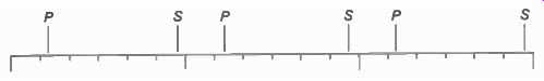
FIGURE 6-9 FOR PROBLEM 8.