The tools and supplies necessary for proper compact disc player Maintenance are not extensive or expensive. Apart from common household tools, you need only a few speciality items to maintain your CD player in good operating condition, and to diagnose minor problems. The section details these tools and supplies, and how to use them.
WORKSPACE AREA
Regular CD upkeep does not require removal of the player from its comfortable nest in your hi-fi System. As long as you dust the cabinet of the player regularly, and provide adequate vent ilation for keeping the power supply cool, you need only remove the player for repair or a Preventative maintenance interval.
For minor repair and Preventative maintenance, you need a work area that’s reasonably free from dust, well lit, and comfortable for you.
Avoid taking your compact disc player out in the garage, where there is a greater chance for dust and airborne oil to cont aminate its inner workings. A kitchen table or inside work area is ideal.
Before going to work on the player, lay out a small piece of clean carpeting or heavy fabric over the work table. This will protect the table as well as the player from scratches and dents. Collect all the tools you'll be using and have them on hand, preferably in a tool box. Special tools and supplies can be stored in an inexpensive fishing tackle box.
The tackle box has lots of small compartments for placing the screws and other parts that you remove.
If you don’t use a box, bor row a cup or bowl from the kit chen to temporarily store parts you remove from the player.
For best results, your workspace should be an area where the CD player will not be disturbed if you have to leave it for several hours or several days. The work-table should also be one that is off limits or inaccessible to young children, or at least an area that can be easily supervised. Some of the chemicals used to clean players and discs are highly toxic, so you should keep them out of reach of children.
There is a risk of electric shock and exposure of infrared laser light when the top of the player is removed. Take every precaution to avoid injury and never leave the player unat tended where curious fingers can touch high voltage wires.
BASIC TOOLS
You'll need a screwdriver and a few other common tools to disassemble the player. Most CD players use Philips screws, so be sure you have a Philips screwdriver handy. Others use flat head or alien screws. Determine which tools you need ahead of time and obtain the proper ones. Don’t try to make do with the wrong tool. Using a small flathead screwdriver to loosen an alien screw only strips the head of the screw.
Be sure to save all the screws you remove; they are not as easily replaced as you think. The majority of compact disc players are made in Japan, and use screws with Japanese met ric threads. You can’t easily find them at hardware stores and they can be expensive if purchased at specialty outlets.
A pair of pliers and a soft rubber mallet are also handy tools to have, although you may not need them. The pliers are used to loosen or tighten nuts, grommets, and plastic standof fs; the mallet is used to tap the cover back on after you've finished. Both of these tools can be misused and can cause ser ious damage if used carelessly. So go easy.
Tweezers or a pair of small long-nosed pliers help you grasp small parts-like screws that have fallen inside the player! A pair of regular manicuring tweezers is fine, but try to get the kind with the flat, blunt end. Tweezers with a pointed end aren’t as useful.
VOLT-OHM METER
A volt-ohm meter is used to test voltage levels and the impedance of circuits. This moderately priced electronic tool is the basic requirement for intermediate compact disc maintenance and repair, and is necessary for anything beyond rout ine cleaning. If you don't already own a volt -ohm meter you should seriously consider buying one. The cost is rather minimal considering the usefulness of the device.
There are many volt-ohm meters (or VOMs) on the market today. For work on compact disc players, you don't want a cheap model and you don’t need an expensive one. A meter of intermediate quality is sufficient and does the job admirably.
The price for such a meter is between $30 and $75 (it tends to be on the low side of this range). Meters and available at Radio Shack and most electronics outlets. Shop around and compare features and prices.
Digital or Analog
There are two general types of VOMs avail able today: digital and analog. The difference is not that one meter is used on digital circuits and the other on analog circuits. Rather, digital meters em ploy a numeric display not unlike a digital clock or watch. Analog VOMs use the older fashioned--still useful--mechanical movement with a needle that points to a set of graduated scales.
Digital VOMs used to cost a great deal more than the analog variety, but the price difference has evened out recently.Digital VOMs, (Fig. 5-1) are fast becoming the standard; in fact, it’s hard to find a decent analog meter anymore.
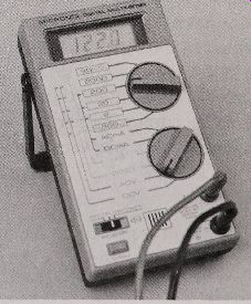
Fig. 5-1. A digital volt -ohm meter, suitable for use with CD players.
Analog VOMs are traditionally harder to use, because you must select the type and range of voltage you are testing, find the proper scale on the meter face, then est imate the voltage as the needle swings into action. Digital VOMs, on the other hand, display the voltage in clear numerals, and with a greater precision than most analog meters.
Because of their increased popularity and ease of use, this section will concentrate on digital VOMs exclusively.
Automatic Ranging
As with analog meters, some digital meters require you to select the range before it can make an accurate measurement. For example, if you are measuring the voltage of a 9-volt transistor battery, you set the range to the setting closest to, but above, 9 volts (with most meters it is the 25 or 50 volt range). Auto-ranging meters don’t require you to do this, so they are inherently easier to use. When you want to measure voltage, you set the meter to volts (either ac or dc) and take the measurement.
The meter displays the results in the readout panel.
Accuracy
Little of the work you'll do with compact disc players require a meter that’s super accurate. A VOM with average accuracy is more than enough.
The accuracy of a meter is the minimum amount of error that can occur when making a specific measurement. For example, the meter may be ac curate to 2000 volts, ±0.8 percent. A 0.8 percent error at the kinds of voltages--used in CD players typically 6 to 12 volts dc--is only 0.096 volts.
Digital meters have another kind of accuracy. The number of digits in the display determines the maximum resolution of the measurements. Most digital meters have 3-1/2 digits, so it can display a value as small as 0.001 (the half digit is a "1" on the left side of the display). Anything less than that is not accurately represent ed; then again, there's little cause for accuracy higher than this when working a compact disc player.
Functions
Digital VOMs vary greatly in the number and type of functions they provide. At the very least, all standard VOMs let you measure ac volts, dc volts, milliamps, and ohms. Some also test capacitance and opens or shorts in discrete components like diodes and transistors.
For our purposes, these additional functions are not necessary, and you need not spend the extra money on a meter that includes them. To make effective measurements, you need to take diodes and transistors out of the circuit to accurately test them.
The design of most compact disc players makes this difficult and inadvisable, even for a seasoned repair technician. (Component failures are usually repaired by service techs by swapping the entire circuit board and not replacing components.)
The maximum range of the meters when measuring volts, milliamps, and resistance also various.
For most applications, including compact disc troubleshooting, the following maximum ratings are more than adequate:
dc Volts
ac Volts
dc Current Resistance
1,000 volt
500 volts
200 milliamps
2 megohms
V Meter Supplies
Most meters come with a pair of test leads one black and one red-each equipped with a needle-like metal probe. The quality of the test leads is usually minimal, so you may want to purchase a better set. The kind with coiled leads are handy. They stretch out to several feet yet recoil to a manageable length when not in use.
Standard leads are fine for most rout ine testing, but some measurements may require the use of a clip lead. These have a spring loaded clip on the end; you can clip the lead in place so your hands are free to do other things. The clips are insulated to prevent short circuits, and you can get clips that at tach onto regular test leads.
Meter Safety and Use
Most applications of the meter involve testing low voltages and resistance, both of which are rela tively harmless to humans. Sometimes, however, you may need to test high voltages--like the input to a power supply--and careless use of the meter can cause serious bodily harm. Even when you’re not actively testing a high voltage circuit, it may be exposed when you remove the cover of the CD player.
If the player is plugged in while the cover is off (which it will be if you’re testing for proper operation), and you’re not measuring voltages at the power supply, cover the power supply terminals, (if exposed) with a piece of cardboard or insulating plastic.
Proper procedure for meter use involves setting the meter beside the unit under test, making sure it is close enough so that the leads reach the test points inside the player. Plug in the leads and test the meter operation by first selecting the resistance function set ting (use the smallest scale if the meter is not auto-ranging). Touch the leads together: the meter should read 0 ohms. If the meter does not respond, check the leads and internal batt ery and try again. If the display does not read 0 ohms, double-check the range and function set tings, and adjust the meter to read 0 ohms (not all digital meters have a 0 adjust, but most analog meters do).
Once the meter has checked out, select the desired function and range, and apply the leads to the player circuits. Usually, the black lead will be connected to ground, and the red lead will be connected to the various test points in the player. Figure 5-2 shows a continuity test of the Power switch on a CD player. The black (ground) lead is clipped to one terminal of the switch; the red lead is touched to the other terminal.
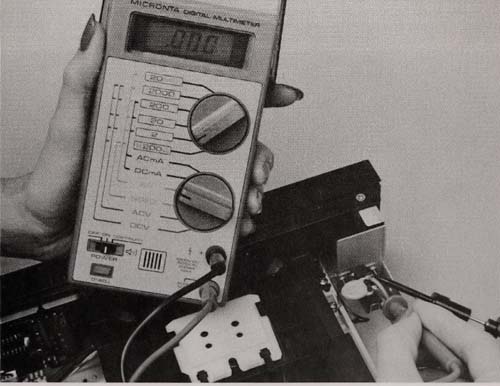
Fig. 5-2. Using the VOM to test the continuity of a switch.
NEVER blindly poke around the inside of a compact disc player in an at tempt to get some kind of reading. Apply the test leads only to those portions of the player that you are familiar with switch contacts, power contacts, and so forth. If you have a schematic diagram for the player, refer to it for the location of the test points.
One safe way to use the meter is to at tach a clip on the ground lead and connect it to the chassis or circuit ground. Use one hand to apply the red lead to the various test point s; stick the other hand safely in your pocket. With one hand ' out of commission," you are less likely to receive a shock because you weren’t watching what you were doing.
LOGIC PROBE
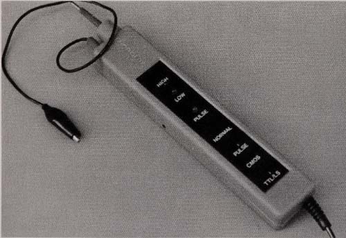
Fig 5-3. A digital logic probe, sometimes helpful in diagnosing CD player
fault Sa For intermediate and advanced troubleshooting.
Meters are typically used for measuring analog signals. Logic probes test for the presence or absence oflow voltage dc signals that represent digital data. The 0’s and 1’s are usually electrically defined as 0 and 5 volts, respectively (although the actually voltages of the 0 and 1 bits depends en tirely on the circuit ). You can use a meter to test a logic circuit, but the results aren’t always predictable. Further, many logic circuits change stat es quickly (pulse) and meters cannot track the voltage switches fast enough.
Logic probes (Fig. 5-3) are designed to give a visual and (usually) aural signal of the logic state of a particular circuit line. One LED on the probe lights up if the logic is 0 (or low), another LED lights up if the logic is 1 (or high). Most probes have a built in buzzer, which has a different tone for the two logic levels. That way, you don't need to keep glancing at the probe to see the logic level.
A third LED or tone may indicate a pulsing signal. A good logic probe can Detect that a circuit line is pulsing at speeds of up to 10 MHz, which is more than fast enough for compact disc player applica tions. The minimum Detect able pulse width (the time the pulse remains at one level) is 50 nano-seconds, again more than sufficient for testing CD players.
Although logic probes may sound complex, they are really simple devices, and their cost reflects this. You can buy a reasonably good logic probe for under $20. Most probes are not battery operated; Rather, they obtain operating voltage by the circuit under test. Unless you plan in-depth troubleshooting and repair of your compact disc player, a logic probe is not as important as a VOM. It is a handy tool to have should the need ever arise, but rout ine Maintenance does not require it.
Using a Logic Probe
The same safety precautions apply when using a logic probe as they do when using a meter. When the cover of the player is removed, potentially dangerous high voltages may be exposed. If you are working close to these voltages, cover them to prevent accidental shock. Logic probes cannot operate with voltages exceeding about 15 volts dc; so if you are unsure of the voltage level of a particular circuit, test it with a meter first to be sure it is safe.
Successful use of the logic probe really requires you to have the circuit schematic to refer to. It’s nearly impossible to blindly use the logic probe on a circuit without knowing what you are testing. And since the probe receives its power from the circuit under test, you need to know where to pick off suitable power. You can easily damage the probe and possibly the circuit under test--if you connect the power leads incorrectly.
To use the probe, connect the probe's power leads to a voltage source on the board, clip the black ground wire to circuit ground, and touch the tip of the probe against a pin of an integrated circuit or the lead of some other component (Fig. 5-4).
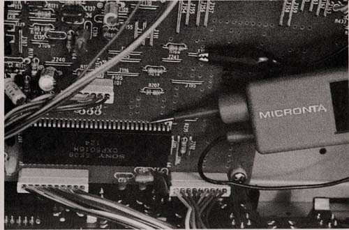
Fig. 5-4. Using the probe to test the logic level at an IC pin.
Please note: CD players often use negative voltages with respect to ground. To the logic probe, there is little difference between connecting the power leads to a positive and ground or connecting the power leads to a negative and ground rail. However, avoid connecting the power leads to a positive and negative rail, because the voltage differential might exceed the maximum supply voltage of the probe. For instance, connecting the lead between the +9 and -9 rails will feed 18 volts to the probe, which is higher than its rated operating voltage.
LASER DETECTOR
Video disc players use a laser that emits a visible beam that’s easy to spot. You can tell that the laser is working just by looking at it. The laser diode used in compact disc players, however, operates at 780 nanometers, which is in the infrared region of the light spectrum. Despite the color ful adver tising ar tthat manufacturers often use to depict the operation of the CD player, the beam is not a bright red streak of light, like the light sabers in a Star Wars movie.
Because you can't see the laser light, you need to use a special infrared light sensor to determine that the laser is indeed working. Such sensors are not readily available at any reasonable cost, but they are easy to make. This section describes the circuit and const ruction details of an inexpensive but versatile laser light sensor. You can also use the sensor to test other sources of infrared light, including the wireless remote control for your CD player.
Bear in mind that you need not const ruct the sensor unless you are actively involved in the repair of compact disc players, or unless you firmly suspect that the laser in your player has gone awry.
The laser diode used in CD players is a long-lasting solid-st ate device, with an average operating life of 5, 000 or more hours, and should long out last most of the mechanical components of the machine. Still, laser diodes are known to break down after only a short period of time. It’s not impossible for a laser diode in a compact disc player to go on the fritz after only one or two years of use.
Circuit Description
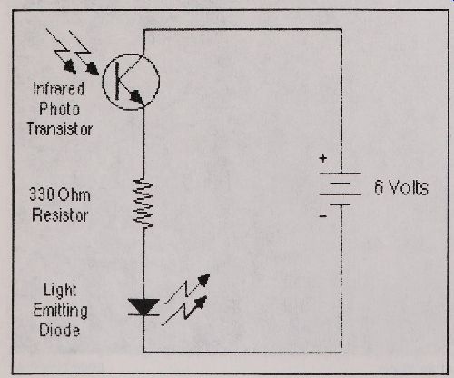
Fig. 5-5. Schematic of the laser light sensor.
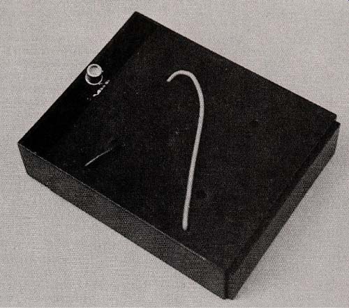
Fig. 5-6. An assembled laser light sensor.
The laser light sensor is a simple circuit that employs only three part s: an infrared phototransis tor, an LED, and a resistor. The schematic is shown in Fig. 5-5. All the parts are commonly available at Radio Shack and most other electronic part stores. You need some sor tof battery supply to operate the circuit. We' ve built the circuit with four AA" bat teies enclosed in a self-contained battery compartment. The compartment also serves as the case for the sensor electronics.
Alternatively, you can use a 9-volt transistor battery mounted in a simple clip holder. The resistor limits the current flowing through the LED, but the 330 ohm value selected is safe for use with supply voltages up to 9 volts. If you use a higher supply voltage, increase the value of the resistor, using Ohms Law. Failure to do this may cause the visible LED in the circuit to burn out. You can determine the value of the resistor by taking the supply/ voltage and subt racting the voltage drop through the LED (usually 1.2 volts). Divide the result by the current you want flowing through the LED (usually about 20 milliamps). For example, with a supply voltage of 9 volts, subt ract -ing the drop in the LED makes 7.8 volts. Divide that by.02 (20 milliamps) and you get 390. The exact value of resistor to use, then, is 390 ohms. There is a lot of slack built into this, because LEDs can take higher currents without risk of damage. On a practical level, don't exceed 30 to 40 milliamps.
For best results, solder the components on a small perforated board, or use an 8-pin IC socket.
The components fit in the contacts of the socket without soldering, but you may wish to solder the leads in place to prevent them from coming out. Soldering into the socket is a little tr icky, because the plastic can melt. An easy way is to fit the compo nent leads into the contacts of the socket, and briefly touch the leads with the tip of the soldering iron. Before the plastic of the socket melts, apply the solder. The electrical contract has already been made inside the socket by the contact s; the solder simply serves to anchor the leads in place. Place the assembly in a box, (Fig. 5-6) to prevent dam age during storage and use. The LED is mounted on the other side of the socket, so that it can be seen when the sensor is pointed towards the optical pickup.
Orientation of both the phototransistor and LED are critical. Installing them backwards will cause the circuit to not work. The phototransistor is marked with a tab or indentation so that you can easily identify the emitter and collector. Refer to the specifications sheets that came with the transistor, or consult a transistor guidebook. The plas tic rim on the cat hode side of the LED is almost always marked with a small indent ation. You can install the resistor in any direction. Be sure to connect the power leads in the proper way too. Reversing the leads could dest roy the phototransistor.
Using the Sensor
You can test the sensor by connecting the batt ery and pointing the phototransistor directly into a bright light (the sun and regular light bulbs all have infrared light content ). The LED should glow.
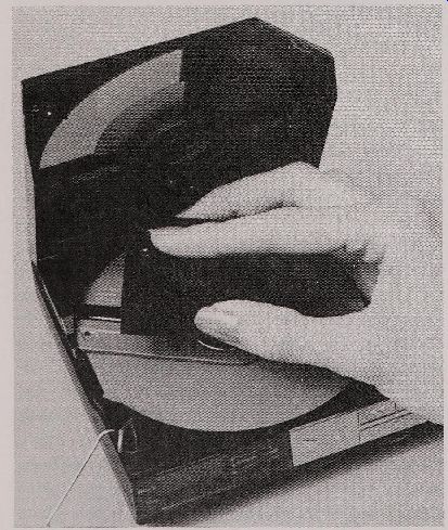
Fig. 5-7. Using the sensor to test the operation of the laser in a portable
player.
If it does not, check your work to make sure the components have been wired correctly (of course, be sure the battery is good; test it with your VOM).
Once you're sure the sensor works, you can test the laser diode in your compact disc player. You must get the phototransistor within one to three inches from the objective lens of the optical pickup for the phototransistor to pick up any light. Figure 5-7 shows the sensor being used on a portable CD player (the LED can be seen at the tip of the index finger ). Note the metal clips inserted into the latching mechanism of the player. These clips defeat the safety interlock switches in the player, so the laser will turn on when the top is open.
This brings us to an important point. The light from the laser diode, though invisible, can cause eye damage if you stare directly into it. When testing the laser diode, keep your eyes out of the direct optical path of the light. Avoid get ting closer than 12 inches from the objective lens.
Defeating Laser Safety Interlocks
You must act ivate the laser to test it, which means you must put the player into Play mode. Ob viously, you also need to remove the top cover of the machine to access the pickup and operate it without a disc. Most drawer -type or door -type players will go into play mode with no disc installed, but only for a moment. During the initial playback stage, the pickup at tempts to read the disc. But be cause there is no disc, the player will soon stop.
Some players, particularly ones that are top loading (including the portables, have a variety of safety interlock features that prevents the laser from turning on unless a disc has been inserted, and the door or cover has been closed. To get the laser to turn on with these, you must locate the interlock switches and defeat them.
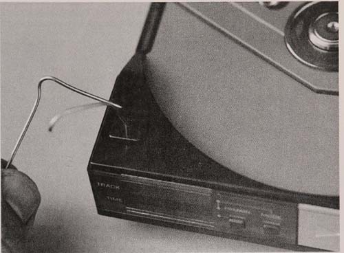
Fig. 5-8. Using bent paper clips to defeat the safety interlock switches,
for testing the laser.
Figure 5-8 shows inserting the pieces of a bent paper clip into the interlock switches of a common portable CD. You can use toot hpicks, paper, or other objects to push the switches closed, to simu late that a disc has been properly loaded. Some interlocks, however, depend on electrical contract made by a pin in the top cover, so you may need to use metallic objects to complete the circuit.
You'll know that the switches have been defeated when you push the play button and the disc spindle starts to spin. With all CD players, the objective lens will pop up and down one to three times during the initial start up time. The pickup is trying to focus on a disc. During this time, the laser is on and you can test it.
Even some drawer and door loading CD players have internal interlock switches. If the disc spinfle does not spin, look for an interlock switch and defeat it. Most interlock switches are located along the side and the back of the loading drawer, as shown in Fig. 5-9, and a few machines have interlock switches at tached to the cabinet. The laser is defeated when the top cover is removed.
Depending on the design of the player, some switches must be closed (depressed) for the laser to work, while others must be open. You might en counter electronic switches; these are optical and sense when a disc is present, light from a small infrared LED is blocked off to a phototransistor. You can easily defeat this type of electronic switch by placing a stiff piece of paper between the LED and photo detector.
If the pickup is tucked too deeply within the player to closely position the phototransistor, you may need to at tach longer leads to the transistor.
Use any insulating wire but keep the lead lengths under six inches if at all possible. Twist the two lead wires together in a braid. You can use shielded wire, the same kind used in audio applications, if the lead length must be longer than six inches.
AMPLIFIER AND SPEAKERS
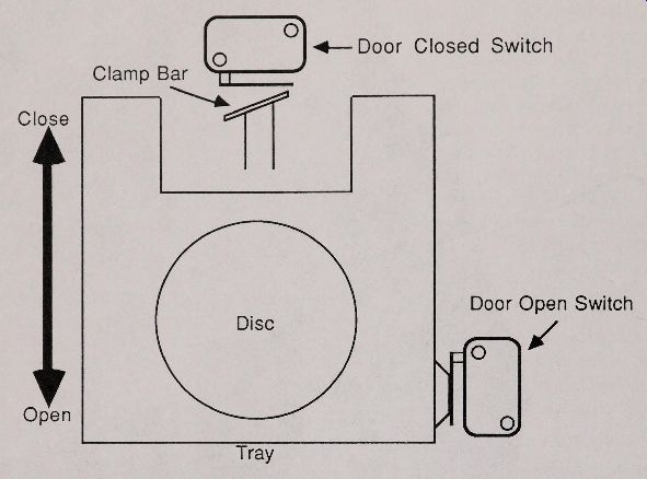
Fig 5-9
A small portable amplifier and speakers are invaluable when troubleshooting and repairing a broken compact disc player. You can keep the CD connected to the amp and test the player as you go through the various troubleshooting procedures.
It’s a lot easier than hooking the player back up to your hi-fi whenever you want to test something.
The amplifier need not be special, but it should be stereo, especially if you're having trouble with the audio output stages of the player. You can use any small speakers that are rated for use with the amplifier. Alternatively, if the amp has a headphone jack, you can use headphones to listen to the audio output. Use Caution, however, because unexpected sound coming through the player can be deafening if the volume is turned up. When not needed, you should take the headphones off.
ASSORTED SUPPLIES
Unlike the family automobile, the compact disc player requires little in the way of oiling and lubing-if at all. Some cleaning and lubrication supplies may be necessary, however, and any wellequipped Maintenance kit will have a little of both.
Spray Cleaner
The cabinet of the player can be cleaned with a damp sponge. If dirt and gr ime are a problem, use a mild spray household cleaner, such as Fantastik or 409. Apply the spray to the sponge or cloth, not directly onto the cabinet. Excess can run inside and possibly cause damage.
Cleaner / Degreaser
Freon, the stuf fused as a coolant in air conditioners, is also a solvent. Unlike most pet roleum based solvents, Freon doesn't melt plastics, and the kind of Freon that you can readily buy is non-toxic and non-flammable. It does have a distinctive odor, but it is harmless.
Freon by itself can be used as a basic degreaser and cleaner. You can use it to remove things like gr ime and dirt in hard to reach places. Freon is available at most any indust rial supply house, or if such a business is not nearby, purchase a can of compressed air at a photographic store. Using the can upside down expels the pure Freon propellant.
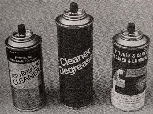
Fig. 5-10. Three commonly available non-residue cleaners
Freon is often mixed with alcohol to make a more potent cleaner. Use caution with this stuf f: it is flammable and toxic. The Freon and alcohol mixture can be used as a general cleaner, a degreaser, even as a lens cleaner for the objective lens mounted in the pickup. Section 6 shows you how to use the mixture to clean the lens.
The Freon/ alcohol mixture is available as an allpurpose cleaner / degreaser that you can buy in a spray can. The cleaner is available at Radio Shack and most any electronics supplies store. Figure 5-10 shows three cans that use Freon and alcohol in various mixtures, but they all pret ty much do the same thing. The cleaners leave no residue, so you can spray it on and it’ll dry with no trace.
The cleaner / degreaser can be used on all the internal components of the compact disc player, ineluding the printed circuit board, optical pickup, and disc loading mechanism. Always remember to turn the player off and let it cool down before spraying. Otherwise, you run the risk of a short circuit.
Spraying the cold liquid on warm parts can crack some components.
Lens Cleaning Material
In addition to Freon and alcohol, you can clean the objective lens on the optical pickup with most any lens cleaner that’s recommended for photo graphic use. Never use lens cleaners or polishers designed for eyeglasses on the optical pickup of a compact disc player. These usually incorporate sili cone, which can adversely react with the coating on the objective, and permanently ruin it.
Keep in mind that cleaning the objective with a fluid is not generally necessary, unless the lens has a thick coating of dustor nicot ine, or has been tainted by a greasy fingerprint. All you'll probably need is a packet of non-treated lens tissues (again, available at photographic stores), or a swab made of cot ton or chamois. Moisten the objective lens with a ''huff" of breath. Avoid rubbing the lens with a dry swab.
Grease and Oil
The mechanical components of a CD player are few and far between, and most do not require any special lubrication. Some lubrication is especially recommended if the player has been used in ad verse environments (a portable or auto CD player would fall into this category) or is more than two or three years old.
Just about any light machine oil can be used for the components that need oiling. The oil should not have anti-rust ingredients. Good candidates are 3-in-1 oil or most any oil designed for sewing machines. Another good oil is that kind designed for musical instruments. The high grade oil comes in a handy applicator bot tle. Some bot tles come with a syr inge-type needle for applying the oil in hard to reach places.
The best oil to use is the kind designed for small machined parts. This oil, which is packed in a small bottle with a syr inge applicator, has special penet rating lubricants that ordinary oils lack.
You can buy this oil at most indust rial supply houses, and some camera and electronics stores.
The "grease" should be a non pet roleum-based product. There are a variety of greaseless lubri cants from which to choose. A light -grade lubricant, such as that used in 35mm cameras, is suitable. You can obtain it from most indust rial supply stores and camera repair shops. A small tube goes a long way.
Refer to Section 6 for more details on common CD components that require oiling and lubrication.
Note that some mechanical components do not require oil or lubrication, and in fact can be harmed by them. Motors fall into this cat egory. It’s a safe bet that if there is no sign that oil or lubricant has ever been present on a mechanical part, it does not need it !
Miscellaneous Cleaning Supplies
There are a variety of other supplies that may ...
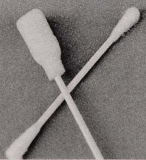
Fig. 5-11. Cotton swabs can leave behind lint ; sponge swabs leave no
fabric that can interfere with the proper operation of the player.
... come in handy when repairing and maintaining a CD player.
Brushes let you dust out dirt.
Contact cleaner enables you to clean the electrical contacts in the player.
Cot ton swabs help you soak up excess oil, lubricant and cleaner.
Sponge-t ipped swabs are like cot ton swabs, but leave no little pieces of lint behind (see Fig. 5-11).
Orange sticks (from a manicure set ) and nail files let you scrape junk off circuit boards and electrical contacts.
The eraser on a pencil goes a long way to rub electrical contacts clean, especially ones that have been contaminated by the acid from a leaking battery.
Modeling put ty (for plastic models) can be used to mend cracks and chips on the plastic exterior of the CD player cabinet.
Contact cement, white glue, and other common adhesives are excellent for repairing broken plastic and metal parts.
A small magnet makes it easier to pick up screws and fer rous metallic objects that have been accident ally dropped into the player.
Non-slip cleaner removes oily build-up from rubber parts like rollers and belts. Alcohol should not be used to clean rubber parts, as it can dry them out.
USING TEST DISCS
Test discs enable you to put your CD through a series of diagnostic procedures that examine the player’s ability to successfully reproduce music on a damaged disc. This may seem Rather daf f, but test discs can be used not only to determine whether a player is well designed, but if its tracking, focusing, and electronic error correction circuits are working properly. If you test your CD with a disc when you first buy it, then again a year later--and the player doesn't fare as well--it’s a good indication that the player needs preventative maintenance.
Commercial Test Discs
You can buy a commercial test disc from any of several CD player manufacturers. The discs conain carefully recorded audio signals that are designed for use in adjusting the player after servicing. As such, the discs aren’t much to listen o, unless you are a fan of single-note tones that go on for minutes. Most test discs also include simu ated damage-dust part icles, scratches, even fin gerprints. The damage is carefully controlled, so hat during playback, you know the extent of disc damage a player can tolerate before it is thrown off course.
The premier test disc is offered by Philips and goes by stock number TS4A. The TS4A disc conains some short music selections that are ob structed by a variety of simulated and deliberate damage. The first type of damage on the TS4A discs a wedge-shaped area on the aluminum signal surace. The wedge was created by scratching the master-disc mold.
The minimum width of the wedge, as seen by the laser, is 400 um. This inner surface wedge is meant to simulate either pinholes in the disc’s alu minum stamping, or scratches on the outside of the disc. Philips says that all players should be able to navigate through the 400 up wedge with no audi ble errors. The wedge enlarges to 500 up and 600 up. Many players can handle these with no probem, as well.
The TS4A disc also includes a series of opaque black dots 300, 500, 600, and 800 / im in diameter, These are painted on the outside of the disc, so the aser actually sees them as much smaller obstrucions when it focuses on the signal surface. The dots are supposed to simulate bubbles in the plastic pro ective layer. Philips says that all players should be able to handle the 300 um dot, but most late-model players can play through most without any problem.
A rect angular gr id of tiny dots represent a real greasy fingerprint. Because the rect angle is or iented so that it is longest in the direction of disc ot ation, the fingerprint test is the toughest one of all. Though it is a difficult test, your player should be able to pass through the fingerprint with little or no error.
Making Your Own Test Discs
The Philips TS4A test disc was engineered at a time when compact disc players were still in their infancy. Player design has improved greatly, and the vast majority of CDs can play through the TS4A disc with no problem. The disc is good to have as a benchmark, but you can put your player through a much more rigorous ordeal by making a test disc yourself. Your own test disc is also cheaper.
You can make a test disc using any CD you already own. The disc will not be damaged, but you should use one that, if accidentally hurt, would pose no great loss. To make the disc, purchase a roll of graphics ar ts tape, the kind used to make thin lines for charting and graphing purposes. You can get the tape at any ar tsupply store and the cost is minimal--under $2.50 for one roll. The tape comes in a variety of colors and widt hs. Black mat te tape that is 1/ 32-inch wide is a good candidate for test discs. Thinner tape is harder to work with and doesn't really stretch the error correction circuitry in the player. You can really test a player’s tracking ability by using 1/ 16-inch wide tape.
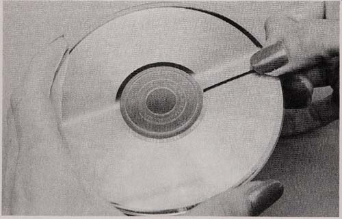
Fig. 5-12. Placing a thin strip of matte black graphics art tape on the
bottom (play side) in order to test the error correction Systems in a player.
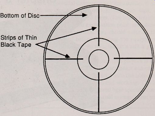
Fig. 5-13. Add more strips on the disc until unconcealed errors occur.
Place the strips opposite each other, like the spokes on a wheel.
--------Bottom of Disc ; strips of Thin Black Tape
Place a strip of the tape radially along the bottom (play) surface of the disc, like a spoke on a wheel (Fig. 5-12). Make sure it adheres to the disc and that the tape is trimmed neatly at the edge.
Don’t worry about the tape damaging the player.
It won't. The worst thing that can happen is the t ape will come off inside the player. Should this happen, and the tape can’t be extracted when you open the drawer, remove the top cover to gain direct access to the pickup area. In any case, if you press the tape onto the disc well enough in the first place, it is unlikely that it will come off.
To the player, the black strip acts as a thick scratch. The 1/ 32" width at the bottom of the disc corresponds to roughly 1 or 2 um at the data surface, which still means that at most, only a few dozen pits will be totally blocked off by the player.
All but the very worst players will track through the single piece of tape. You can test the threshhold of your player by adding more strips.
Place a second strip opposite to the first, and try the disc. Add two more strips 90 degrees away from the other two (Fig. 5-13). Try the disc again. A good player will be able to play with up to six to eight strips on the disc before errors are heard.
You can use your test disc to evaluate a player before you buy it. If the player doesn't seem to be able to handle the disc with any more than three or four strips, you may want to look at another machine. You can also use the test disc as a benchmark. Try the test disc when your machine is new.
Note it’s upper threshhold, the maximum number of black strips it can accommodate before audible errors occur.
At regular intervals--say every six to 12 months--recheck the operation of the player with the same disc. If the player can't accommodate as many strips, it’s a good indication that it is in need of a checkup. The objective lens in the optical pickup might be dirty, or the slide rails used in the transport may be sticking due to an accumulation of dustor nicotine. See Section 6 for more information on Preventative Maintenance procedures.
= = = =