The special features of the FET which recommend this transistor for use in oscillators (see Section 3) also enable it to perform efficiently in low-powered transmitter circuits. In fact, many tube type oscillator and r-f amplifier circuits for transmitters need no change other than voltage reduction if the tubes are replaced with suitable FET's. This means that standard coils, tuning capacitors, and chokes may be used, and also that no loss results in capacitance type interstage coupling in transmitters and exciters. Furthermore, the high input impedance of the FET tends to preserve the high Q of the transmitter tank circuit.
Low-powered circuits offering high overall efficiency and relative simplicity are possible in this area with FET's. The transmitter circuits described in this Section are of especial interest to the radio experimenter, novice, and ham. But they will also suggest applications to communications professionals. In addition to actual transmitters, some accessory devices for use in transmitting stations are described. Additional devices may be found in Section 7.
Operation of transmitters is regulated by the Federal Communications Commission (FCC). Be sure you are complying with their rules and procedures before you attempt to put a signal "on the air."
SINGLE-STAGE CRYSTAL-CONTROLLED TRANSMITTER
Fig. 1 shows the circuit of a simple crystal-controlled, oscillator type c-w transmitter with a low-impedance output. This single stage unit, based on a 2N3823 FET, covers the amateur bands from 10 to 80 meters and is capable of 56 milliwatts d-c power input.
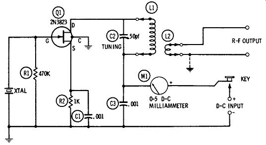
Fig. 1. Single-stage 56-mw crystal-controlled transmitter.
The circuit is that of the basic drain-tuned crystal oscillator. The tuned tank circuit comprises 50-pf variable capacitor C2 and tank coil L1. Each plug-in "coil" consists of a tank coil ( L1) and link coupling coil (L2) as a unit ( Millen low-powered, single-ended 40,000 series, or equivalents), and separate plug-ins are available for the 10-, 20-, 40-, and 80-meter ham bands. The 20-meter unit can be used also for the 21-meter band. Special coils wound to suit individual demands will cover other frequencies.
The low-impedance output may feed a coaxial antenna feeder directly, or may operate into a suitable antenna coupler. In portable emergency applications, a whip antenna may be connected directly to the top of coil L1.
With the key depressed, the circuit is tuned, without antenna or other load, by adjusting C2 for drain-current dip, as indicated by 0-5 d-c milliammeter M1. The antenna then is connected and any adjustments made to the antenna coupler ( if one is used) to "load" the drain current up to the highest value at which the oscillator starts readily each time the key is closed. Drain current is 1.40 ma at 6 vdc, 1.41 ma at 9 vdc, 2.0 ma at 15 vdc, and 2.5 ma at 22.5 vdc.
With an active crystal, the oscillator can be made to act as a doubler, i.e., tank L1-C2 may be tuned to twice the crystal frequency. The r-f output will be lower, however, than in straight through operation.
In addition to serving as a single-stage transmitter, this circuit may also be used as the crystal oscillator in a multistage transmitter.
Either inductive or capacitive output coupling may be used in the latter application.
All wiring must be kept as short and rigid as practicable. And the fourth pigtail of the 2N3823 (being internally connected to the metal case of this FET) must be grounded as shown. Resistors R1 and R2 are 1/2 watt; capacitors C1 and C3 are mica.
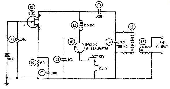
Fig. 2. Single-stage 0.8-watt crystal-controlled transmitter.
SINGLE-STAGE 0.8-WATT CRYSTAL-CONTROLLED TRANSMITIER
The U222 FET will provide a maximum of 1 watt r-f output at frequencies as high as 200 MHz. This capability makes the U222 especially attractive for transmitter use.
Fig. 2 shows the circuit of a single-stage crystal-controlled c-w transmitter using the U222. This circuit is similar to the one de- scribed in the preceding section, except that the U222 circuit em ploys shunt feed of the d-c supply through a 2.5-mh r-f choke (LS). This allows the bottom of the tank circuit, L1-C4, to be grounded.
Plug-in coil sets ( L1-L2) permit the transmitter to be tuned to any frequency for which a crystal is available. Each plug-in set consists of a tank coil ( L1) and link-coupling coil (L2) assembled as a unit.
The Millen 40,000 series of low-powered single-ended coils provides sets for the 10-, 20-, 40-, and 80-meter ham bands (the 20-meter set can be used also for the 21-meter band). For non-ham frequencies, other L1-L2 coils may be wound to suit individual demands.
The circuit is tuned, with the key depressed and with no antenna or other load, by adjusting C4 for drain-current dip, as indicated by 0-50 d-c milliammeter M1. Then, the antenna is connected and any adjustments made to the antenna coupler (if one is used) to "load" the drain current up to 35 ma minimum. At this point, the d-c power input is 0.8 watt. The low-impedance output may be connected directly to a coaxial antenna feeder or may operate into a suitable antenna coupler.
Like the preceding single-stage transmitter (Fig. 1), this one may serve either as a complete c-w transmitter or as the oscillator of a multistage transmitter.
Resistors R1 and R2 are 1/2 watt, and capacitors C1, C2, and CS are mica. All wiring must be short and rigid, for stability. The gate electrode of the U222 is internally connected to the metal case of this FET which accordingly must be kept out of contact with other components.
TWO-STAGE TRANSMITTER
Fig. 3 shows the circuit of a crystal-controlled oscillator-amplifier type of transmitter, employing single-ended stages. A 2N3823 FET is used in the oscillator ( Q1) and a U222 FET in the r-f amplifier (Q2). The d-c power input of the amplifier is 0.8 watt.
The oscillator is tuned by tank circuit L1-C2. Here, L1 is a plug in coil chosen to resonate with C2 at the crystal frequency. The amplifier is tuned by tank circuit L2-C6, and here a plug-in coil set (L2-L3) is used: L2 resonates with C6 at the crystal frequency, and LS is a link-coupling coil. For ham bands, the oscillator and amplifier coils both may be commercial low-powered units, such as the Millen 40,000 series of single-ended units. For L1, the main coil is used without the link winding. The low-impedance R-F OUTPUT terminals of the transmitter can feed a coaxial antenna feeder directly or can operate into a suitable coupler for a higher frequency antenna.
A single 0-1 d-c milliammeter ( M1) is used for tune-up purposes.
When meter switch S1 is in its OSC position, the meter is switched across 27-ohm resistor R3, the scale is converted to 0-3 ma, and the meter reads oscillator current; when S1 is in its AMP position, the meter is switched across 1.3-ohm shunt resistor R6, the scale is converted to 0-43 ma, and the meter reads amplifier current. (Both shunt resistors are stock values). The transmitter is tuned to the crystal frequency, in the conventional manner, by adjusting first the oscillator capacitor (C2) and then the amplifier capacitor (C6) for drain-current dip. Common drain-current values are 2.5 ma for the oscillator and 35 ma for the amplifier.
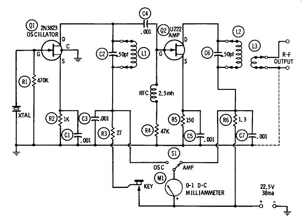
Fig. 3. Two-stage transmitter.
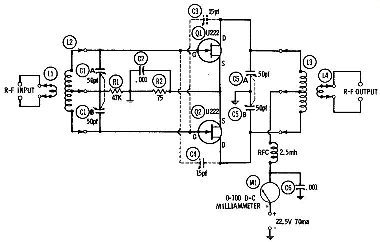
Fig. 4
All wiring must be kept short, direct, and rigid as practicable.
Overall shielding, such as complete enclosure in a metal box, is advantageous but not mandatory. However, the fourth pigtail of the 2N3823 (being internally connected to the metal case of this FET) must be grounded as shown. The gate electrode of the U222 is internally connected to the metal case of that FET, so the U222 must be kept clear of all contact with other components and wiring. All fixed resistors are 1/2 watt, and all fixed capacitors are mica.
PUSH-PULL FINAL AMPLIFIER
A push-pull final amplifier capable of approximately 1.6 watts d-c power input is shown in Fig. 4. This amplifier may be driven by the two-stage circuit shown in Fig. 3 or by the crystal oscillator shown in Fig. 2. Two U222 FET'S are used.
The amplifier employs link-coupled input and output (low-impedance coupling coils L1 and L4). For ham bands, plug-in coils (such as the Millen 40,000 series, low-powered, center-tapped type) may be used both for the input ( L1-L2) and output (L3-L4) tanks. Both tanks are tuned to the incoming frequency.
In many instances, the amplifier will self-oscillate and will need to be neutralized. The 15-pf variable capacitors (CS, C4) are indicated for this purpose, but will not be needed in every layout. The circuit should be tried first without them, noting if self-oscillation occurs at any setting of tuning capacitors C1A-C1B and C5A-C5B.
Neutralizing is accomplished in a conventional manner.
All wiring must be kept short, direct, and rigid; and care should be taken to avoid contact between the FET's or between them and other components, since the gate electrode is internally connected to the metal case of the U222. Resistors R1 and R2 are 1 watt, and capacitors C2 and C6 are mica.
Current drain is approximately 70 ma at 22.5 volts, but may be higher with individual FET's.
100-MHz GROUNDED-GATE AMPLIFIER
The grounded-gate FET amplifier is the counterpart of the grounded-grid h1be amplifier. Neither of these amplifiers requires neutralization; hence, both are usable at very high frequencies in circuits which are simpler than they otherwise might be. The grounded-gate ( and grounded-grid) amplifier has the additional advantage of somewhat higher output than that of the grounded source, grounded cathode, or grounded emitter under similar operating conditions, since most of the excitation power also appears in the amplifier output.
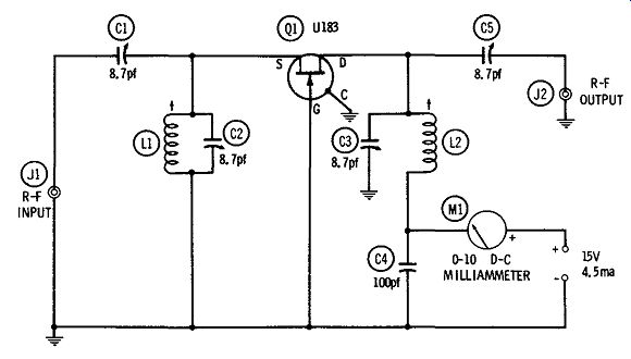
Fig. 5. 100-MHz grounded-gate amplifier.
Fig. 5 shows the circuit of a grounded-gate r-f amplifier suitable for 100-MHz use. Employing a Ul83 FET, this amplifier has 50-ohm input and output (available through coaxial jacks J1 and J2, respectively). In this arrangement, the input (source-to-gate) circuit is tuned by means of tank L1-C2, and the output (drain-to-gate) circuit by means of tank L2-C3. Variable capacitors C1 and C5 are used for coupling and impedance matching. Each of the variable capacitors ( C1 to C5) has a maximum capacitance of 8.7 pf (E. F. Johnson 160-104 midget, or equivalent) and each of the tank coils ( L1, L2) is a slug-tuned 0.184-0.275-µh unit ( Miller 40A227CBI, or equivalent). The coil slugs are set to tune the tanks to 100 MHz with C2 and C3 at half-capacitance.
Current drain is 4.5 ma at 15 vdc; this corresponds to a d-c power input of 67.5 mw. The r-f input (driving) power is approximately 4mw.
All wiring must be kept as short, direct, and rigid as practicable; and the fourth pigtail of the Ul83, being internally connected to the metal case of this FET, must be grounded as shown. Fixed capacitor C4 must be silvered mica.
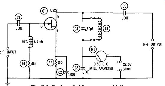
Fig. 6. Single-ended frequency multiplier.
SINGLE-ENDED FREQUENCY MULTIPLIER
Fig. 6 shows the circuit of a single-ended frequency-multiplier stage. Although this circuit gives best efficiency as a frequency doubler, it may also be used as a tripler. Operation is entirely conventional: the output tank ( L1-C4) simply is tuned to twice or to three times the frequency of the r-f input, as desired.
The circuit, which employs a single U222 FET, may be driven by either of the crystal oscillators described earlier (Fig. 1 and 5-2), but substantially higher output as a doubler or as a tripler will be obtained when the oscillator of Fig. 2 is used as the driver.
Inductance L1 is selected to resonate with capacitance C4 at the desired multiple of the input-signal frequency. For the ham bands, plug-in coils may be any of the commercial low-powered units, such as the Millen 40,000 series. Either capacitive output coupling may be used, as shown in Fig. 6, into a high-impedance load; or low-impedance inductive coupling may be obtained with the link coil supplied as part of the commercial plug-in coils ( L1). The d-c power input is approximately 0.8 watt (35 ma at 22.5 vdc). Drain-current dip, as indicated by 0-50 d-c milliammeter M1, indicates correct tuning of the multiplier.
All wiring must be kept short, direct, and rigid; and since the gate electrode of the U222 is internally connected to the metal shell of this FET, the latter must be kept out of contact with other components and wiring. All resistors are 1/2 watt, and all fixed capacitors are mica.
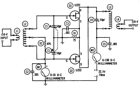
Fig. 7. Push-push doubler.
PUSH-PUSH DOUBLER
The push-push doubler, using two tubes or transistors, gives approximately twice the r-f power output of the single-ended doubler.
Fig. 7 shows the circuit of a push-push doubler employing two U222 FET's.
Note that, in the conventional manner, the gates are connected in push-pull and the drains in parallel. Because of this arrangement, a center-tapped input tank coil (L2) and single-ended output tank coil (L3) are required. (Both tanks are link coupled, the input through L1 and the output through L4). The inductance of L2 is selected to resonate with dual tuning capacitor C1A-C1B at the input frequency, and the inductance of L3 to resonate with tuning capacitor C4 at twice the input frequency. Input- and output-coil sets may be low-powered commercial plug-in units, such as the Millen 40,000 series.
Tuning procedure is conventional: Tune the input tank to the input frequency by adjusting C1A-C1B for peak deflection of milli ammeter M1, then adjust the output tank for drain-current dip at twice the input frequency, as indicated by milliammeter M2. The d-c power input is approximately 1.6 watt (70-ma drain current at 22.5 vdc). All wiring must be as short, direct, and rigid as practicable. Resistors R1 and R2 are 1 watt, and all fixed capacitors are mica. The U222's must be kept clear of contact with each other and with wiring and other components, since the gate electrode is internally connected to the metal case of this FET.
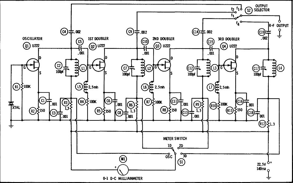
Fig. 8.
FOUR-BAND EXCITER
Fig. 8 shows the circuit of a standard four-band exciter for ham radio. This arrangement consists of a crystal oscillator ( Q1) followed by three doublers (Q2, Q3, Q4), each stage containing a single U222 FET. The output (fl) of the oscillator or that of the doublers (f2, f3, f4) is selected, as desired, by means of the single pole, 4-position rotary switch, S2. All r-f outputs are capacitance coupled (through C4, C9, Cl4, and Cl9, respectively). In a popular application of this type of exciter, the crystal oscillator operates in the 80-meter band, and the doublers in the 40-, 20-, and 10-meter bands, respectively.
The various stages are tuned by means of separate tank capacitors: C2 for the oscillator; C7, first doubler; C12, second doubler; and C17, third doubler. Each stage is tuned, in the conventional manner, starting with the oscillator and progressing through the exciter, for drain-current dip. For economy in this tuning, a single 0-1 d-c milliammeter (M1) is switched (by means of S1) across a shunt resistor (R5, R6, R9, R12) in any stage being adjusted. These resistances are low enough that they introduce only negligible loss in the exciter, but multiply the meter to approximately 0-42 ma full scale. The scheme is much simpler than would be required if the lines had to be broken to insert the meter and closed after completion of the measurement. The 1.3-ohm resistors are stock 5 percent units. Where economy is unimportant, however, a separate 0-50 d-c milliammeter may be installed in each stage.
The d-c power input is approximately 0.8 watt per stage (35 ma at 22.5 vdc). Total current drain for the exciter is 140 ma.
All wiring must be kept as short, direct, and rigid as practicable.
All resistors are 1/2 watt, and all fixed capacitors are mica. The U222's must be kept clear of contact with each other and with wiring and other components, since the gate electrode is internally connected to the metal case of this FET.
BALANCED MODULATOR
For single-sideband operation, the FET makes possible a triode type balanced modulator which is compact and low powered. Fig. 9 shows such a balanced-modulator circuit employing two matched 2N4340 FE T's. Note that the a-f (modulating) signal is applied to the gates in push-pull through transformer T1 and that the r-f (carrier) signal is applied to the sources in parallel through capacitor C3.
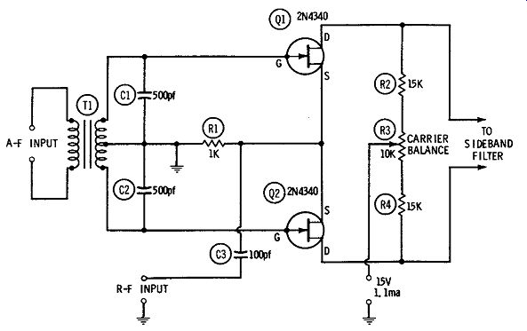
Fig. 9. Balanced modulator.
Cancellation of the carrier in the output circuit (only the two sidebands which result from the modulation remaining) results from the symmetry of the circuit. To ensure this symmetry, there must be close correspondence between the two halves of the circuit. This means that the secondary winding of transformer T1 must be accurately center tapped, the two FET's must be matched, C1 must match C2, and R2 must match R4. Any slight unbalance due to these components or to circuit strays may be corrected by adjustment of the CARRIER BALANCE potentiometer, R3. Total current drain is 1.1 ma at 15 vdc.
All wiring must be kept as short, direct, and rigid as practicable, and the circuit should be enclosed within a grounded shield box. All fixed resistors are 1/2 watt, and all fixed capacitors are silvered mica. The 2N4340's must be kept clear of contact with each other and with wiring and other components, since the gate electrode is internally connected to the metal case of this FET. The terminal arrangement of the FET's can be checked against the drawings shown in Section A. Manufacturers may be obtained from Appendix B, and the addresses are shown in Section C.
C-W MONITOR
Fig. 10 shows the circuit of a simple monitor for c-w telegraphy.
Requiring no connection to the transmitter and containing its own power supply, this device may be placed conveniently on the operating desk. It will give a reliable aural check of signal quality, as well as making the keying audible.
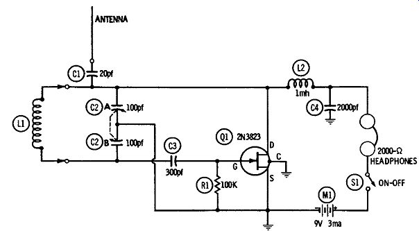
Fig. 10. C-w monitor.
The circuit is that of a Colpitts-type oscillating detector employing a single 2N3823 FET. The signal is tuned in by the dual 100-pf variable capacitor C2A-C2B. The antenna may be any convenient whip; short, stiff, vertical wire; or flexible, insulated, scatter lead which will pick up enough signal for a comfortable headphone level. The tuning capacitor may be detuned above or below the signal for the most pleasing beat tone. Total current drain is 3 ma at 9vdc.
Inductance L1 is chosen to resonate with one-half C2A-C2B (i.e., with 50 pf) at the signal frequency. For ham-band operation, a set of low-powered commercial plug-in coils, such as the Millen 40,000 series, may be used to cover the 3.5- to 30-MHz spectrum.
The volume delivered by a pair of high-impedance magnetic headphones will be sufficient in most environments, especially with medium- and high-power transmitters. However, a transistorized audio amplifier may be added to the monitor if speaker operation or louder headphone signals are desired.
All wiring must be kept as short, direct, and rigid as practicable, and the monitor circuit should be enclosed in a shield box to which the circuit is grounded. For further shielding, the fourth pigtail of the 2N3823 (which is internally connected to the metal case of this FET) must be grounded as shown. Resistor RI is 1/2 watt, and capacitors C1, C3, and C4 are mica. The terminal arrangement for the FET is shown in Appendix A.
MODULATING THE FET TRANSMITTERS
The FET transmitters shown in this Section are depicted for c-w telegraph operation. They may be amplitude modulated for telephony. however, by short-circuiting the telegraph key and connecting a suitable a-f speech amplifier/modulator unit in series with the transmitter d-c supply, as shown in Fig. 11.
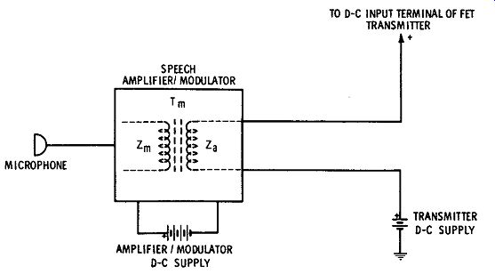
Fig. 11. Amplitude-modulation arrangement.
The only requirements are that the a-f power output of the modulator must be at least twice the d-c drain power input of the transmitter, and that the impedance ( Z.,) of the modulator output transformer, T111 , match the impedance of the transmitter. Table 1 shows the values of impedance (for each of the applicable transmitters in this Section) which transformer Tm in the modulator must match. It also shows the a-f output power needed to modulate each of the transmitters 100 percent. The primary impedance ( Z111 ) of the transformer matches the impedance of the transistor(s) in the modulator.
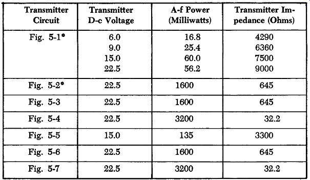
Table 1. A-M Modulator Data "Modulated oscillators are prohibited
in some services.
Note that the modulation must be applied to the final r-f stage in the transmitter circuit given in Fig. 3.
SINGLE-CONTROL ("TNT") TRANSMITTER
Fig. 12 shows the circuit of a c-w transmitter. This is a variation of the tuned-plate, tuned-grid (TPTG) oscillator which uses tuning only in the output circuit. An untuned coil is used in the input circuit. This accounts for the descriptive term TNT ( "tuned, non tuned").
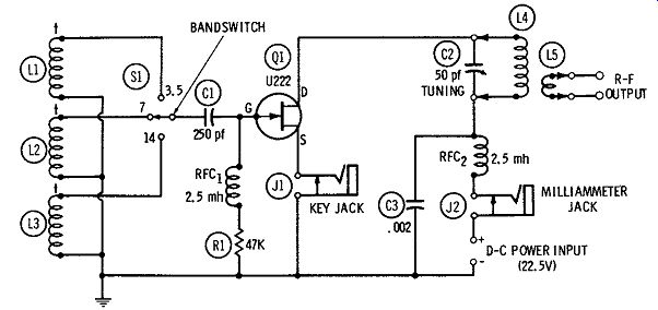
Fig. 12. Single-control ("TNT") transmitter.
In the arrangement shown here, the drain circuit is tuned by means of 50-pf variable capacitor C2 and a plug-in coil. Each plug in coil set ( Millen 43,000 Series, or equivalent), consists of an untapped main coil (U) and end link (L5). Three sets provide coverage of the 3.5-, 7-, and 14-MHz amateur bands. Corresponding un tuned gate coils ( L1, L2, and L3) for these bands are selected by means of single-pole, three-position switch SL The gate coils are pre-adjusted by means of their screwdriver-operated tuning slugs.
(L1, 3.5-MHz band, Miller No. 40A475CBI. L2, 7-MHz band, Miller No. 40A155CBI. L3, 14-MHz band, Miller No. 40A336CBI). The U222 FET (Q1) draws 35 ma at 22.5 volts de, a d-c input corresponding approximately to 0.8 watt. Lower d-c voltages will produce correspondingly lower power input. A 0 to 50 d-c milliammeter plugged into jack J2 allows drain current to be read at intervals, or it can be monitored continuously.
In operation, the transmitter may be tuned throughout each band simply by adjusting variable capacitor C2. There is sufficient distributed capacitance and circuit capacitance across the gate coil ( L1, L2, LS) in most layouts that this coil, in true TNT fashion, needs no separate tuning. However, the transmitter output will be maximum around the one frequency at which the gate coil tends to self-resonate, and will fall off somewhat at higher and lower frequencies. The optimum gate-coil inductance which will give best output through out the band may be selected by adjusting the gate-coil slug, varying capacitor C2, and noting the relative output as indicated by an r-f vtvm connected to the R-F OUTPUT terminals, or by a 2-volt pilot lamp (with a 1-turn pickup coil) coupled to tank coil L4. In most instances, the gate coil will be adjusted for peak output at the center of the band. When maximum efficiency is desired at some extreme frequency in any band, the appropriate gate coil may be re-trimmed for maximum output at that frequency.
The gate coils must be mounted at right angles to each other and separated as widely as practicable, to prevent power absorption by the unused two. For maximum isolation, L1, L2, and LS may be enclosed in separate shield cans.
Closed-circuit jacks are used both for the key (J1) and drain milliammeter (J2). This allows the circuit to restore itself automatically when the key or meter is removed.
To prevent parasitic oscillation, all leads must be as short, rigid, and direct as practicable. The U222 must be mounted clear of wiring, chassis, and all other components, since the gate electrode is internally connected to the metal case of this FET. Resistor R1 is 2 watts, and capacitors C1 and CS are mica. Selector switch S1 must be ceramic insulated.
The TNT circuit may be used as a doubler ( 3.5 to 7 MHz, and 7 to 14 MHz) if a driving signal is fed into the gate coil and the drain tank is tuned to twice the driving frequency.
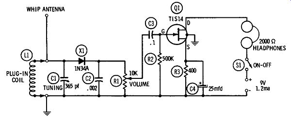
Fig. 13. Phone monitor.
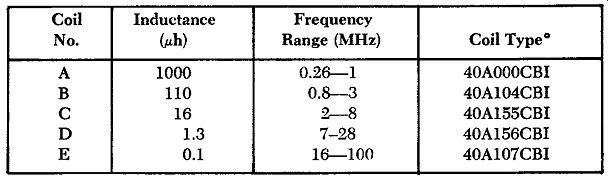
Table 2. Phone Monitor Coil Data ~Catalog numbers of J. W. Miller
Co.
PHONE MONITOR
A tuned diode detector with headphones is often used to monitor radiophone transmissions. The semiconductor diode has the advantage in this application that, at least for large signals, its response is linear, so that it gives a faithful check of the monitored signal. But its output is relatively low, so that the headphone signal cannot compete with room noise.
The solution is to use a headphone amplifier following the detector. Fig. 13 shows an arrangement of this sort. The advantage of a field-effect transistor (here a TIS14 unit, Q1) is the resultant zero loading of the detector by the amplifier.
A short whip antenna will pick up adequate signal from the transmitter. The signal is tuned in by means of 365-pf variable capacitor C1 which resonates with plug-in coil L1 at the signal frequency. Table 5-2 gives data for coils to cover the frequency range of 0.26 to 100 MHz in five bands. The specified units are miniature, ceramic, slug-adjusted coils which may be set exactly to frequency during calibration of the monitor. For plug-in purposes, these coils may be mounted inside 1 inch-diameter 4-prong forms, such as Millen Type 45004. For narrower-band tuning than is afforded by this coil assortment (example: amateur or citizens' bands), a lower capacitance (for example, 50 or 100 pf) should be used for C1.
The detector is an inexpensive 1N34A germanium diode ( X1). Audio output of the diode, developed across load resistor R1, is applied to the gate of the TIS14. Capacitor C3 blocks the d-c component in the output of the diode. Since the load resistor ( R1) is a potentiometer, efficient control of headphone volume is assured.
Current drain is 1.2 ma at 9 vdc.
Tuning capacitor C1 is a midget, broadcast-type variable. C2 is a mica capacitor, and C3 a 100-volt plastic unit. C4 is a 25-dcwv electrolytic. Resistors R2 and R3 are 1/2 watt.
All wiring must be as short, direct, and rigid as practicable. A fourth pigtail of the TIS14 is internally connected to the metal case of this FET and must be grounded as shown, for shielding.
The monitor may be calibrated by loosely coupling coil L1 to an amplitude-modulated r-f signal generator, tuning in generator signals at selected frequencies by adjusting C1 for loudest headphone response, and graduating the C1 dial accordingly.
[Note: This guide is based on Sams "FET Circuits", pub'd in 1961]