Solid-state test equipment has long been prized for its complete portability, electrically clean operation, and total isolation from the power line. In all classes of such equipment, the bipolar transistor, often in company with the semiconductor diode, brought about many improvements. However, its use generally necessitated design compromises. But the FET, being more nearly like the vacuum tube, demands few compromises in the transistorizing of standard instrument circuits.
The electronic voltmeter is a clear example of successful transistorization via the field-effect transistor. Here, the FET has faith fully preserved the high input resistance ( 1 megohm or more per volt) which is characteristic of the vacuum-tube voltmeter, whereas transistorization via the bipolar transistor usually afforded an input resistance of only 100,000 ohms per volt. Another example is the highly useful dip oscillator; in this instrument, the FET provides the same high sensitivity and excellent selectivity that is characteristic of the grid-dip oscillator.
This Section describes several simple instruments which are made efficient, reliable, and completely portable by the FET. For circuits in other Sections, which may be used for instrumentation, see Figs. 2-11, 2-12, 2-13, 3-1, 3-2, 3-3, 3-4, 3-7, 3-8, 3-9, 3-10, 4-7, 5-10, and 6-6.
SINGLE-FET ELECTRONIC DC VOLTMETER
Fig. 1 shows a transistorized version of the extremely useful d-c vacuum-tube voltmeter. This instrument, which ( like its vtvm counterpart) has a constant input resistance of 11 megohms on all ranges, employs a single 2N4340 FET. ( I megohm of the input resistance is accounted for by isolating resistor RI in the probe.)
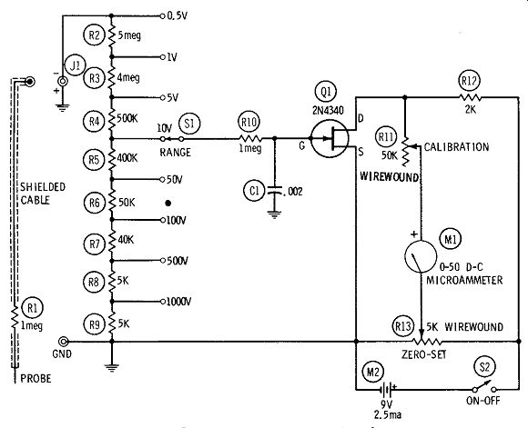
Fig. 1. Electronic d-c voltmeter (single FET).
The instrument covers 0 to 1000 volts in eight ranges: 0-0.5, 0-1, 0-5, 0-10, 0-50, 0-100, 0-500, and 0-1000 selected with single-pole, 8-position, non-shorting rotary switch SL The range resistors ( R2 to R9) in the input voltage-divider string must be accurate to at least 1 percent. Some of these ( 400K and 4 meg) are not stock values and must be made up by series-connecting available resistors (500K + 100K, and 3 meg + 1 meg, respectively). Linearity of response is within +2 percent of full scale.
Resistor R10 and capacitor C1 form a filter to remove any stray fluctuations picked up by the test leads. Rheostat R1l is the CALIBRATION control mounted safely inside the instrument case, and potentiometer R13 is the front-panel ZERO-SET. The 0-50-microampere scale of meter M1 reads direct on the 50 volt range and is read on the 0.5-, 5-, 50-, and 500-volt ranges by mentally shifting the decimal point, as required. On the 1-, 10-, 100-, and 1000-volt ranges, however, the readings must be mentally multiplied by 2 or some multiple of 2 (by 0.02 for the 1-volt, by 0.2 for the 10-volt, by 2 for the 100-volt, and by 20 for the 1000-volt range). To calibrate the instrument:
1. Set switch S1 to the 1-volt range.
2. Set rheostat R1l approximately to the center of its range.
3. Plug the test leads into jack J1 and the GND terminal.
4. Close switch S2.
5. Adjust potentiometer R13 to zero the meter.
6. Connect an accurately known 1-volt d-c source to the input ( negative to the shielded test lead, positive to the GND terminal).
7. Adjust rheostat R11 for exact full-scale deflection of meter M1.
This rheostat then need not be touched again until the instrument is routinely recalibrated.
A diode rectifier operated ahead of the input voltage divider will adapt the instrument for a-c voltage measurements but will require special meter scales and calibrations, in addition to the d-c ones.
All fixed resistors are 1 watt, and variable resistors R1l and R13 both are wirewound ( the former is provided with a slotted shaft for screwdriver adjustment). Capacitor C1 may be mica or ceramic.
The 2N4340 must be kept clear of contact with the chassis or other components, since the gate electrode is internally connected to the metal case of this FET. Current drain from the 9-volt battery, \12, is 2.5 ma.
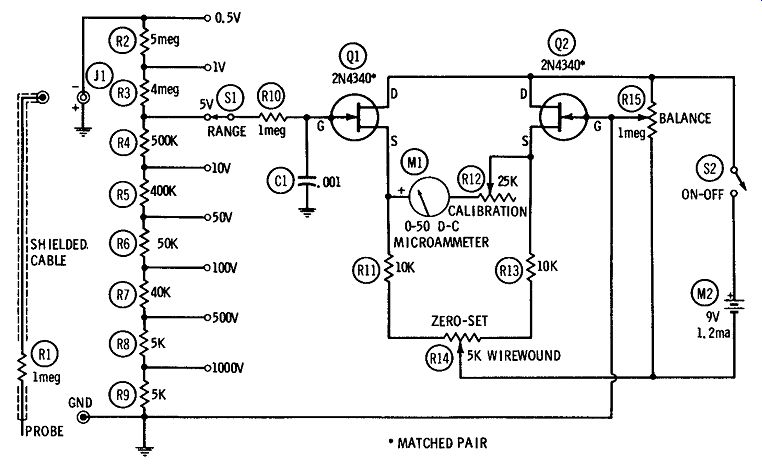
Fig. 2.
BALANCED ELECTRONIC DC VOLTMETER
As in vacuum-tube voltmeters, a symmetrical (balanced) FET d-c voltmeter is superior to the single-ended circuit described in the preceding section. The balanced circuit exhibits less temperature drift, and therefore requires fewer zero re-settings than in the simpler circuit. It also draws less current from the power supply during normal operation.
Fig. 2 shows a balanced d-c voltmeter circuit employing two 2N4340 FET's. For best results, these FET's must be matched, and may be so obtained from the manufacturer. The circuit is essentially that of a resistance bridge, the four arms of which are (1) the internal drain-to-source resistance of FET Q1, (2) the internal drain-to-source resistance of FET Q2, ( 3) R1l and that part of R14 to the left of the slider, and ( 4) R13 and that part of R14 to the right of the slider. Adjustment of potentiometer R14 balances the bridge and thus zeroes the meter. Application of a test voltage to the gate of Q 1 ( through the input terminals of the instrument)
changes the internal resistance of Q1, unbalancing the bridge, and causes the meter to deflect.
The instrument covers 0 to 1000 volts in eight ranges: 0-0.5, 0-1, 0-5, 0-10, 0-50, 0-100, 0-500, and 0-1000 volts selected with single pole, 8-position, non-shorting rotary switch SL The range resistors ( R2 to R9) must be accurate to at least 1 percent. Some of these ( 400K and 4 meg) are not stock values and must be made up by series-connecting available resistors ( 500K + 100K, and 3 meg + 1 meg, respectively). Linearity of response is within + 2 percent of full scale. The input resistance of the instrument is constant at 11 megohms on all ranges ( 1 megohm of this is accounted for by the isolating resistor, R1, in the test probe). Resistor R10 and capacitor C1 form a filter to remove any stray fluctuations picked up by the test leads. Rheostat R12 is the CALIBRATION control mounted safely inside the instrument case, and potentiometer R14 is the front-panel ZERO-SET. Potentiometer R15 ( also mounted safely inside the case) is used to balance the circuit by varying the grid bias on Q2 before the instrument is placed into service.
The 0-50--microampere scale of meter M1 reads direct on the 0-50--volt range and is easily read on the 0.5-, 5-, 50-, and 500-volt ranges by mentally shifting the decimal point, as required. On the 1-, 10-, 100-, and 1000-volt ranges, however, the reading must be multiplied by 2 or some multiple of 2 (by 0.02 for the 1-volt, by 0.2 for the 10-volt, by 2 for the 100-volt, and by 20 for the 1000-volt range).
The circuit must be initially balanced in the following manner:
1. Unplug the test leads from jack J1 and GND.
2. Set switch S1 to its 0.5-volt range.
3. Close switch S2.
4. Adjust potentiometer R14 to zero the meter, changing the set ting of rheostat R12 if necessary to get a readable deflection of the meter when unzeroed.
5. Temporarily ground the gate of FET Q1; this should drive the meter from zero. Without touching R14, adjust R15 to rezero the meter.
6. Remove the ground from the Q1 gate; this should drive the meter from zero. Without touching R15, reset R14 to rezero the meter.
7. Again, ground the gate of Q1 and note if the meter reads off zero. If it does, repeat Step 5.
8. Continue to alternate between these steps until the zero set ting of the meter is undisturbed by grounding the gate of Q1. Potentiometer R15 then should be protected from tampering.
After this initial balancing adjustment, the instrument may be calibrated in the following manner:
1. Set switch S1 to the 1-volt range.
2. Set rheostat R12 to approximately the center of its range.
3. Plug the test leads into jack J1 and the GND terminal.
4. Close switch S2.
5. Adjust potentiometer R14 to zero the meter.
6. Connect an accurately known 1-volt d-c source to the input ( negative to the shielded test lead, positive to the GND terminal).
7. Adjust rheostat R12 for exact full-scale deflection of meter M1.
This rheostat then need not be touched again until the meter is routinely recalibrated.
A diode rectifier may be operated ahead of the input voltage divider to adapt the instrument to a-c voltage measurements. however, this will require special meter scales and calibrations, in addition to the d-c ones.
All fixed resistors are 1 watt, variable resistors R12 and R14 both are wirewound, and variable resistor R15 ( because of its high resistance) is a composition type. R12 and R15 each should have a slotted shaft for screwdriver adjustment. Capacitor C1 may be mica or ceramic. The 2N4340's must be kept clear of contact with each other or with the chassis, wiring, or other components, since the gate electrode is internally connected to the metal case of this FET. Current drain from the 9-volt battery, ~2, is 1.2 ma.
ELECTRONIC AC VOLTMETER
Fig. 3 shows the circuit of a high-impedance electronic a-c volt meter suitable for audio and ultrasonic tests and measurements. This circuit, which is based on a single 2N4868 FET, has an input impedance of 1 megohm in series with 0.1 microfarad on all voltage ranges.
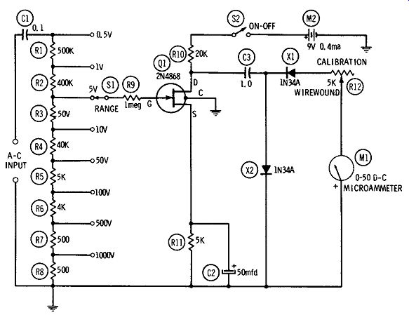
Fig. 3. Electronic a-c voltmeter.
The instrument covers 0 to 1000 volts rms in eight ranges: 0-0.5, 0-1, 0-5, 0-10, 0-50, 0-100, 0-500, and 0-1000, selected with single pole, 8-position, non-shorting rotary switch SL The range resistors ( R1 to RB) must be accurate to at least 1 percent. Two of these ( 400K and 4 meg) are not stock values and must be made up by series-connecting available resistors ( 300K + 100K, and 3 meg + 1 meg, respectively). Linearity of response is within 5 percent of full scale. Frequency response, referred to 1 kHz, is down 3.5 db at 50 Hz and 2 db at 50 kHz.
The circuit is the conventional amplifier-rectifier arrangement: the signal is amplified first by the FET and then is rectified by the two germanium diodes ( X1, X2). The d-c output of the diodes is more than sufficient to drive meter M1 to full scale when a signal voltage of 0.5 volt rms is applied to the AC INPUT terminals. The meter deflection is proportional to the average value of the a-c signal voltage, but the meter may be calibrated to read rms voltage on a sine-wave basis.
No zero adjustment is needed. Rheostat R12, the CALIBRATION control, is mounted safely inside the instrument case to protect it from tampering after the instrument has been calibrated.
The 0-50-microampere scale of the meter reads direct on the 0-50-volt range, and is easily read on the 0.5-, 5-, 50-, and 500-volt ranges by mentally shifting the decimal point, as required. On the 1-, 10-, 100-, and 1000-volt ranges, however, the reading must be mentally multiplied by 2 or some multiple of 2 ( by 0.02 for the 1 volt, by 0.2 for the 10-volt, by 2 for the 100-volt, and by 20 for the 1000-volt range). Calibrate the instrument in the following manner:
1. Set switch S1 to the 5-volt range.
2. Set rheostat R12 to full resistance.
3. Close switch S2.
4. Connect an accurately known 5-volt rms a-c source to the A-C INPUT terminals ( any frequency between 60 Hz and 1 kHz).
5. Adjust rheostat R12 for exact full-scale deflection of meter M1.
This rheostat then need not be touched again until the instrument is routinely recalibrated.
All fixed resistors are 1 watt. Capacitor C1 is a 1000-volt ceramic unit (Sprague 5HK-P10, or equivalent), C2 a 25-dcwv electrolytic, and C3 a 200-volt metallized paper tubular (Aerovox P8292ZN, or equivalent). Rheostat R12 is a wirewound unit which has a slotted shaft for screwdriver adjustment. The fourth pigtail of the 2N4868 is internally connected to the metal case of this FET and must be grounded as shown. Current drain from the 9-volt battery, M2, is 0.4 ma.
ELECTRONIC AC VOLTMETER/MILLIVOLTMETER
For more sensitive a-f and ultrasonic voltage measurements than are permitted by the circuit described in the preceding section, the two-transistor circuit shown in Fig. 4 is recommended. The additional amplification available in this latter arrangement permits full scale deflections down to 0.1 volt ( 100 mv) rms.
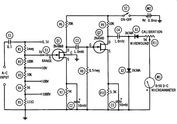
Fig. 4. A-f voltmeter/millivoltmeter.
Based on one 2N4868 FET ( Q1) and one 2N4340 FET (Q2), the instrument covers 0 to 1000 volts rms in five ranges: 0-0.1, 0-1, 0-10, 0-100, and 0-1000, selected with the single-pole, 5-position, non-shorting rotary switch S1. The range resistors ( R1 to R5) must be accurate to at least 1 percent. One of these ( R5) is not a stock value and must be made up by series-connecting one 100- and one 11-ohm resistor. (This odd resistance makes it possible to hold the other four resistors to stock values. ) Frequency response, referred to 1 kHz, is down 4 db at 50 Hz and 3 db at 50 kHz. Linearity is within 5 percent of full scale on each range.
Like the simpler a-c voltmeter (Fig. 3 ), this instrument uses the conventional amplifier-rectifier arrangement: the signal is amplified by the two FET's ( Q1, Q2), then is rectified by two germanium diodes ( X1, X2) whose d-c output drives microammeter M1. Deflection of the meter is proportional to the average value of the a-c signal voltage, but the meter may be calibrated to read rms voltage on a sine-wave basis.
No zero adjustment is needed. Rheostat R11, the CALIBRATION control, is mounted safely inside the instrument case to protect it from tampering after the meter has been calibrated.
Unless special scales are drawn for the meter, voltages must be determined from the 0-50-microampere scale by mentally multiplying the deflection by some multiple of 2 (by 0.002 for the 0.1-volt, by 0.02 for the 1 volt, by 0.2 for the 10-volt, by 2 for the 100-volt and by 20 for the 1000-volt range). Calibrate the instrument in the following manner:
1. Set switch S1 to its 10-volt range.
2. Set rheostat R1l to full resistance.
3. Close switch S2.
4. Connect an accurately known 10-volt rms a-c source to the A-C INPUT terminals ( any frequency between 60 Hz and 1 kHz).
5. Adjust rheostat R1l for exact full-scale deflection of meter M1.
The rheostat then need not be touched again until the meter is routinely recalibrated.
All fixed resistors are 1 watt. Capacitor C1 is a 1000-volt ceramic unit (Sprague 5HK-P10, or equivalent), C3 is a 200-volt metallized paper tubular, and C2 and C5 are 25-dcwv electrolytics. Rheostat R11 is a wirewound unit which has a slotted shaft for screwdriver adjustment. The fourth pigtail of the 2N4868 ( Q1) is internally connected to the metal case of this FET and must be grounded as shown, but the gate electrode of the 2N4340 ( Q2) is internally connected to the metal case of the latter FET, which accordingly must be kept clear of contact with wiring, chassis, and other components. Current drain from the 9-volt battery, M2, is 0.8 ma.
The terminal arrangement for the FET's is shown in Sect A.
Manufacturers of FET's can be obtained from Sect. B, and the addresses of the manufacturers are shown in Sect. C.
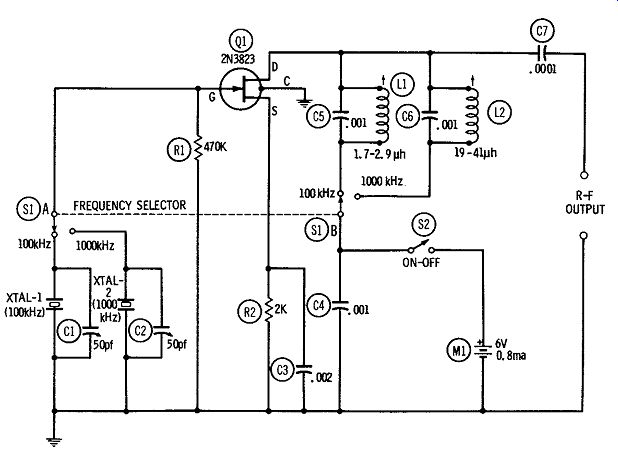
Fig. 5. Crystal dual-frequency standard.
CRYSTAL DUAL-FREQUENCY STANDARD
Fig. 5 shows the circuit of a dual crystal oscillator with output selectable at either 100 or 1000 kHz. Both signals give strong harmonics for calibration purposes far into the high-frequency spectrum. The circuit is based on a single 2N3823 FET. A dpdt FREQUENCY SELECTOR switch ( S1A-S1B) connects the 100-kHz crystal and the first tank ( L1-C5) into the circuit for 100-kHz output, or the 1000-kHz crystal and the second tank ( L2 C6) into the circuit for 1000-kHz output. The tank coils are slug tuned for maximum output signal, as indicated by an a-c vtvm or transistorized electronic a-c voltmeter connected to the appropriate output terminals. ( L1 is a Miller No. 42A223CBI, or equivalent; L2 is a Miller No. 42A335CBI, or equivalent.) Each crystal frequency is adjustable over a narrow range by means of a 50-pf trimmer capacitor ( C1, C2) to standardize the outputs against WWV transmissions or other standard-frequency signals.
All wiring must be kept as short, direct, and rigid as practicable.
Also, wiring should be kept well away from metal chassis or case, to minimize stray capacitance which will bypass higher harmonics of the signals. Capacitors C3, C4, and C7 are mica; C5 and C6 are silvered mica. The fourth pigtail of the 2N3823 is internally connected to the metal case of this FET and must be grounded as shown. Current drain from the 6-volt battery, M1, is 0.8 ma.
100-kHz/10-kHz
SECONDARY FREQUENCY STANDARD
The secondary frequency standard circuit shown in Fig. 6 has a 100-kHz oscillator and 10-kHz multivibrator. This arrangement provides 100-kHz harmonics far into the high-frequency spectrum, and each 100-kHz interval is subdivided by harmonics of the multi vibrator. The oscillator is based on a single 2N3823 FET ( Q 1) and the multivibrator on two 2N4340 FET's (Q2, Q3). The oscillator is tuned to the crystal frequency by adjusting the slug-tuned coil, L1 ( Miller No. 42A223CBI, or equivalent) and the crystal frequency is adjustable over a narrow range, by means of 50-pf trimmer capacitor C1, to standardize the 100 kHz against WWV transmissions or other standard-frequency signals. The 100 kHz output is capacitance coupled through capacitor C3.
Synchronizing 100-kHz voltage is injected into the multivibrator through potentiometer R5 which, with R4, forms the gate resistor of FET Q2. The 10-kHz output is capacitance coupled through capacitor C6.
The multivibrator is best adjusted by connecting the 100-kHz output of the instrument to a communications receiver, tuning in two adjacent 100-kHz harmonics on the receiver, closing switch S1, and adjusting potentiometer R5 until exactly nine intermediate ( 10-kHz) signals can be counted between each two adjacent 100 kHz harmonics. Adjustment of R5 will cause the intermediate points to jump abruptly from one number to another as the multivibrator synchronizes at 7, 8, 9, 10, or 11 kHz. When the 10-kHz harmonics are not wanted, switch S1 may be opened, and only the 100-kHz harmonics will remain.
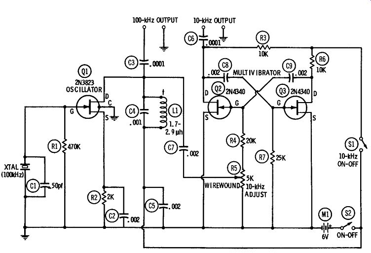
FIG. 6
The 10-kHz fundamental is separately available, through capacitor C6, as a highly accurate audio frequency, as a square wave, and as a synchronizing signal.
All wiring must be kept as short, direct, and rigid as practicable.
Also, wiring should be kept well away from metal chassis or case, to minimize stray capacitance which will bypass higher harmonics of the signals. All fixed resistors are 1/2 watt, and all fixed capacitors are silvered mica. Potentiometer R5 is wirewound and provided with a slotted shaft for screwdriver adjustment; it should be mounted safely inside the instrument case to protect it from tampering. The fourth pigtail of the 2N3823 is internally connected to the metal case of this FET and must be grounded as shown. The gate electrode of the 2N4340 is internally connected to the metal case in the latter FET, however, so both 2N4340's must be kept clear of contact with each other or with wiring, chassis, or other components.
Total current drain from the 6-volt battery, M1, is 2.2 ma.
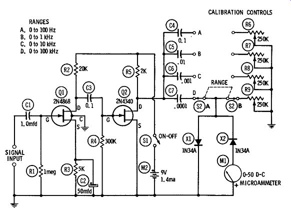
Fig. 7. Direct-reading audio-frequency meter.
DIRECT-READING AUDIO-FREQUENCY METER
A direct-reading audio-frequency meter is a convenient instrument. Feed an unknown audio frequency into its input terminals and read the frequency directly from the meter scale. No adjustments of any kind need be made; only the frequency range must be switched in the same way that a voltmeter range is switched.
Fig. 7 shows the circuit of such an instrument, based on one 2N4868 FET ( Q1) and one 2N4340 FET (Q2). This instrument covers 0 to 100 kHz in four ranges: 0-100 Hz, 0-1 kHz, 0-10 kHz, and 0-100 kHz. The frequency is indicated on the scale of microammeter M1, and the indication is independent of signal amplitude from 1.7 volts rms upward and is independent of waveform over a wide range. The response is linear; hence, only one point need be calibrated in each frequency range.
The circuit exploits the same principle employed in some tube type frequency meters: It is essentially two overdriven amplifier stages in cascade. The output of the last stage accordingly is a square wave which is applied to an r-c circuit ( R6-R9 and C4-C7) and diode rectifiers X1 and X2. Since the square wave is limited ( i.e., of constant amplitude), the deflection of meter M1 depends only on the number of pulses passing through this meter during each second, so is directly proportional to the pulse frequency.
The frequency meter must be calibrated at one point in each of its four ranges ( the best point is the top frequency in each range). Rheostats R6, R7, RS, and R9 are the CALIBRATION controls, and these units are provided with slotted shafts for a screwdriver.
They are also mounted safely inside the instrument case to protect them from tampering. Follow this calibration procedure:
1. Close switch S1.
2. Set range switch S2 to position A.
3. Connect an accurate audio oscillator to the SIGNAL INPUT terminals and set its output to 2 to 3 volts rms.
4. Set the signal frequency to 100 Hz and adjust R6 for full scale deflection of meter M1.
5. Set S2 to position B.
6. Set the signal frequency to 1 kHz and adjust R7 for full-scale deflection of the meter.
7. Set S2 to position C.
8. Set the signal frequency to 10 kHz and adjust RS for full-scale deflection of the meter.
9. Set S2 to position D.
10. Set the signal frequency to 100 kHz and adjust R9 for full-scale deflection of the meter.
All wiring must be kept as short, direct, and rigid as practicable.
All fixed resistors are 1/2 watt. Capacitors C1 and CS are 400-volt metallized paper tubulars, and C2 is a 25-dcwv electrolytic. Capacitors C4 and C5 are 200-volt metallized paper tubulars, and C6 and C7 are silvered mica. While the range capacitors ( C4 to C7) should be reasonably accurate, any deviation in capacitance will be compensated by adjustment of the calibration controls ( R6 to R9). The fourth pigtail of the 2N4868 is internally connected to the metal case of this FET and must be grounded as shown. In the 2N4340, however, the metal case is internally connected to the gate electrode, so this latter FET must be kept clear of contact with wiring, other components, or chassis. Current drain from the 9-volt battery, M2, is 1.4 ma.
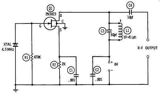
Fig. 8. Television sound-marker generator (4.5-MHz).
4.5-MHz SOUND-MARKER GENERATOR
Fig. 8 shows the circuit of a 4.5-MHz crystal oscillator for sound-channel alignment in tv receivers. This oscillator, based on a single 2N3823 FET, is tuned to the crystal frequency by adjusting the slug-tuned tank coil, L1 (Miller No. 42A335CBI, or equivalent) for maximum output, as indicated by a communications receiver or an r-f voltmeter connected to the R-F OUTPUT terminals.
The open-circuit signal amplitude at the R-F OUTPUT terminals is 4.0 volts rms when the d-c supply is 6 volts at 1.4 ma. The signal strength may be continuously adjusted by making C4 a 50-pf midget variable capacitor.
Resistors R1 and R2 are 1/2 watt.
Capacitors C1, C2, and C4 are mica, and capacitor CS is silvered mica. The fourth pigtail of the 2N3823 is internally connected to the metal case of this FET and must be grounded as shown.
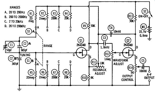
Fig. 9. Variable-frequency audio oscillator.
VARIABLE-FREQUENCY AUDIO OSCILLATOR
Fig. 9 shows the circuit of a variable-frequency r-c-tuned audio oscillator employing two 2N4340 FET's. Using the Wien-bridge frequency-determining network, this instrument covers 20 Hz to 200 kHz in four ranges: 20-200 Hz, 200-2000 Hz, 2-20 kHz, and 20-200 kHz. Tuning in each range is accomplished with a dual 365-pf variable capacitor (C2), and ranges are changed by switching identical resistors in pairs ( R1-R5, R2-R6, R3-R7, and R4-R8). These resistances must be accurate to at least 1 percent.
In this circuit there are two feedback paths, both through capacitor C4. One is through the band-switched Wien bridge to the gate of FET Q1, the other is through FEEDBACK ADJUST rheostat R1l to the source of Q1. At the resonant frequency of the Wien bridge, the feedback to the Q1 gate is positive and creates oscillation. The feedback through R11, however, is negative and, since it cancels the oscillation on all frequencies except the bridge resonant frequency, is responsible for the very low distortion of this type of circuit.
The amplitude of the negative feedback is adjustable with rheostat R1l, and the amplitude of the driving voltage presented to the feedback/ output amplifier ( Q2) is adjustable with potentiometer R12. Optimum adjustment of these two controls results in lowest distortion of the output signal.
The low-impedance, source-follower output is adjustable with potentiometer R14 from approximately zero to 0.4 volt rms. Current drain is 0.8 ma from the 22.5-volt battery, M1. Higher output amplitude ( at the same current drain for the oscillator) may be obtained with an additional output-amplifier stage.
The tuning capacitor ( C2) must be insulated from the metal chassis and should be enclosed in a grounded shield box. The lower section of this capacitor is grounded, but the upper section floats and must be compensated with the 50-pf trimmer capacitor, C1.
Solid construction must be employed throughout, and all wiring must be short, direct, and rigid.
The oscillator may be calibrated in the conventional manner against any available standard audio frequency, using an oscilloscope set up for Lissajous figures. Another method makes use of a calibrated audio-frequency meter ( see an earlier section of this Section) connected to the A-F OUTPUT terminals. With switch S1 set to the proper range, capacitor C2 is adjusted to resonance with the standard frequency ( or to the desired frequency, as indicated by the audio-frequency meter). The dial of this tuning capacitor then is set to that frequency. Trimmer capacitor C1 is adjusted for continuous oscillation throughout the range.
Rheostat R11 is adjusted for constant output over the entire range of the oscillator. as indicated by an electronic a-c voltmeter or oscilloscope connected to the A-F OUTPUT terminals. Potentiometer R12 is adjusted for minimum distortion ( as indicated by an oscilloscope or distortion meter connected to the A-F OUTPUT terminals). After adjustment, these two variable resistors need not be touched again until the instrument is routinely rechecked.
All fixed resistors are 1 watt. Capacitors C4 and C5 are 50-dcwv electrolytics, and capacitor C3 is a 200-volt metallized paper tubular. Rheostat R1l and potentiometer R12 have slotted shafts for screwdriver adjustment and are mounted safely inside the instrument case to protect them from tampering. Trimmer capacitor C1 is also inside the case, being securely fastened to the frame of tuning capacitor C2. The gate electrode of the 2N4340 is internally connected to the metal case of this FET, so both 2N4340's must be kept clear of contact with each other, other components, wiring, or chassis.
DIP OSCILLATOR
The tube-type grid-dip oscillator is a well-known and useful instrument which needs no theoretical explanation nor a recitation of its merits here. Previously, some transistorized versions of this device, while offering freedom from the power line, have been less satisfying than the tube type, since the bipolar transistor reduced sensitivity and selectivity of the circuit. With an FET, however, the dip oscillator behaves just as it does with a tube, because the gate to-ground impedance of the FET is comparable to the grid-to ground impedance of the tube. Response is sharp and fast, and the indicating meter need not be connected in some special part of the circuit different from the grid circuit of the tube.
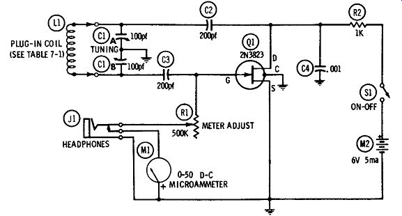
Fig. 10. Dip oscillator.
Fig. 10 shows the circuit of a dip oscillator, based on a 2N3823 FET. With six plug-in coils, this instrument covers the range 1.1 to 95 MHz: (A) 1.1-2.5 MHz, (B) 2.5-5 MHz, (C) 5-11 MHz, (D) 10-25 MHz, ( E) 20-45 MHz, and ( F) 40-95 MHz. The circuit is that of a Colpitts oscillator tuned with a dual 100-pf variable capacitor, C1.
Dip is indicated by the 0-50 d-c microammeter, M1, in the gate to-ground leg, and the meter sensitivity is adjustable with rheostat R1. Downward deflection is sharp when the tank ( L1-Cl) is tuned to the resonant frequency of an external 1-c circuit to which the tank is loosely coupled.
Like other dip oscillators, this one is useful for checking signals as well as dead 1-c circuits. A closed-circuit jack, J1, is provided for high-resistance magnetic headphones used for this purpose.
When the headphones are plugged in, the microammeter is automatically disconnected from the circuit.
The instrument may be calibrated in either of two ways: ( 1)
Loosely couple L1 to a succession of dead l-c tank circuits whose frequencies are accurately known, tune C1 successively for dip at the various frequencies, and mark the dial of this variable capacitor correspondingly, or ( 2) With headphones plugged into jack J1, tune in a number of accurately known signals, adjusting C1 for zero beat at each frequency and marking the dial of the tuning capacitor correspondingly.
--------------------
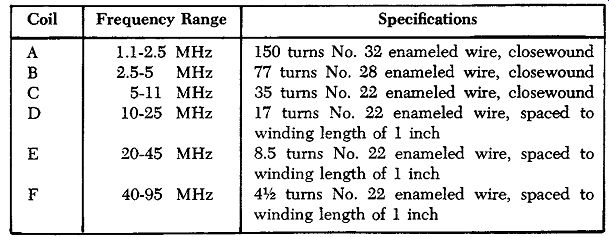
Table 1. Coil-Winding Data0
Coil Frequency Range Specifications
B 2.5-5 MHz 77 turns No. 28 enameled wire, closewound
C 5-11 MHz 35 turns No. 22 enameled wire, closewound
D 10-25 MHz 17 turns No. 22 enameled wire, spaced to winding length of 1 inch
E 20-45 MHz 8.5 turns No. 22 enameled wire, spaced to winding length of 1 inch
F 40-95 MHz 41,i! turns No. 22 enameled wire, spaced to winding length of 1 inch
------------------
For stability, the instrument must be solidly constructed, and the shortest, most direct, and most rigid wiring practicable must be used. All coils are tightly wound on I-inch-diameter plug-in forms (see Table 7-1 for coil-winding data). The number of turns in the coils may need some adjustment to compensate for stray capacitance in an individual instrument and for the particular gate to-source capacitance of an individual FET. Resistor R2 is 1/2 watt, and capacitors C2, CS, and C4 are silvered mica. The fourth pigtail of the 2N3823 is internally connected to the metal case of this FET and must be grounded as shown. Current drain, from the 6-volt battery, M2, is 5 ma.
The steady deflection of the microammeter does not have the same value on all frequency ranges and may even change to a higher or lower value as the instrument is tuned through a single range. Adjustment of rheostat R1, however, enables the operator to set the pointer of M1 to a desirable point on the scale before tuning for dip. This rheostat also provides some degree of volume control when the instrument is used with headphones.
A-F MILLIAMMETER
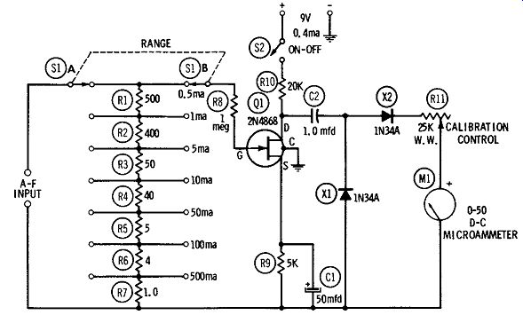
Fig. 11. A-f milliammeter.
Fig. 11 shows the circuit of an audio-frequency milliammeter, based on a single 2N4868 FET ( Q 1), which covers the current range 0 to 500 ma in seven full-scale ranges: 0.5, 1, 5, 10, 50, 100, and 500 milliamperes. A 2-pole, 7-position, rotary selector switch ( S1) switches in the appropriate values of shunt resistance ( R1 to R7). The double-pole switching guarantees that the circuit is never exposed to excessive current between switch positions. Linearity of response is within 5 percent of full scale. Frequency response, referred to 1 kHz, is down 3.5 db at 50 Hz and 2 db at 50 kHz. Current drain is 0.4 ma at 9 vdc.
Input-resistance values are: 0.5 ma, 1000 ohms; 1 ma, 500 ohms; 5 ma, 100 ohms; 10 ma, 50 ohms; 50 ma, 10 ohms; 100 ma, 5 ohms; and 500 ma, 1 ohm.
Like the a-f milli-voltmeters described earlier in this Section, this circuit uses the conventional amplifier-rectifier arrangement: the signal is developed by current through the selected shunt resistors and is first amplified by the FET and then rectified by the two germanium diodes ( X1, X2). The d-c output of the diodes is more than sufficient to drive microammeter M1 to full scale. The meter deflection is proportional to the average value of the input a-f current, but the meter may be calibrated to read rms current on a sine-wave basis.
No zero adjustment is needed. Rheostat R1l, the CALIBRATION control, is mounted safely inside the instrument case to protect it from being turned by accident after the instrument has been completely calibrated.
The 0 to 50 DC microampere scale of meter M1 reads directly on the 50-ma range, and is easily read on the 0.5-, 5-, and 500-ma ranges by mentally shifting the decimal point as required. On the 1-, 10-, and 100-ma ranges, however, the reading must be mentally multiplied by 2 or some multiple of 2 ( thus, by 0.02 for the 1-ma, by 0.2 for the 10-ma, or by 2 for the 100-ma range of the a-f milliammeter). Calibrate the instrument in the following manner:
1. Set switch S1 to the 50-ma range.
2. Set rheostat R1l to full resistance.
3. Close switch S2.
4. Connect an accurately known 50-ma a-c source to the A-F INPUT terminals ( any frequency between 60 Hz and 1 kHz).
5. Adjust rheostat R1l for exact full-scale deflection of meter M1.
This rheostat then need not be touched again until the instrument is routinely recalibrated.
The instrument is now in calibration on all ranges if accurate values have been used for resistors R1 through R7.
All fixed resistors are 1 watt. ( The range resistors-RI to R7 must be accurate to at least 1 percent.) Capacitor C1 is a 25-dcwv electrolytic; C2 is a 100-volt plastic unit. Rheostat R1l is a wire wound unit provided with a slotted shaft for screwdriver adjustment.
For stability, all wiring must be as short, rigid, and direct as practicable; and the fourth pigtail of the 2N4868, which is internally connected to the metal case of this FET, must be grounded as shown, for shielding.
INDUCTANCE CHECKER
Any inductance between 60 µh and 60,000 hy may be checked by the resonance method, using the circuit shown in Fig. 12 with a variable-frequency audio oscillator. With the unknown inductance connected to terminals X-X, the oscillator is tuned for peak deflection of meter M1, whereupon the inductance is determined ( in terms of the .01-mfd capacitance, CS) by calculation or by reference to the graph in Fig. 13.
In this circuit ( Fig. 12), the U 183 FET ( Q1 ) serves as a source follower between the oscillator and the measuring circuit. The ad vantages of this arrangement are (a) the high input impedance of the resultant circuit reduces oscillator loading to virtually zero, and ( b) the follower isolates the measuring circuit ( M1- X1-C3-Lx) from the signal source.
Potentiometer R1 allows adjustment of the gain for exact full scale resonant deflection of meter M1. This is an added convenience even when the audio oscillator has its own output control. With R1 set for maximum gain, an oscillator output of 1.5 volts rms will drive meter M1 to full scale with most inductors which will be connected to terminals X-X. D-c microammeter M1 is made to respond to alternating current simply by connecting the 1N34A germanium diode ( X1) in parallel with it. Current drain of the circuit is 3.3 ma at 9 vdc.
Resistor R2 is 1/2 watt. Capacitor C1 is a 100-volt plastic unit; C2 is a 25-dcwv electrolytic. For stability and accuracy, CS must be a silvered mica capacitor as close as practicable to the rated .01 mfd, since it is with reference to this capacitance that the unknown inductance is determined.
The checker must be built mechanically solid, and all wiring must be as short, rigid, and direct as possible. A fourth pigtail of the Ul83 is internally connected to the metal case of this FET and must be grounded as shown, for shielding.
To use the checker:
1. Connect a variable-frequency audio oscillator ( tuning range: 20 to 200,000 Hz) to the OSCILLATOR INPUT terminals.
2. Connect the unknown inductance ( Lx) to terminals X-X.
3. Close switch S1, and switch on the oscillator.
4. Starting at the bottom of the lowest frequency range, tune the oscillator slowly throughout its ranges until a sharp deflection of meter M1 occurs. Adjust the oscillator output control and gain-control potentiometer R1 to bring this deflection close to full scale of the meter.
5. At this point of peak deflection, read the frequency from the oscillator dial.
6. For close results, calculate the inductance: 1 L, = -(-3-95-f~ 2 -X-l~0-- 9 ~) where, Lx is the unknown inductance, in henrys, f is the oscillator frequency, in hertz.
7. For approximate results, eliminating calculations, use the chart given in Fig. 13.
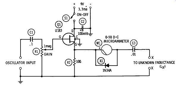
Fig. 12. Inductance checker.
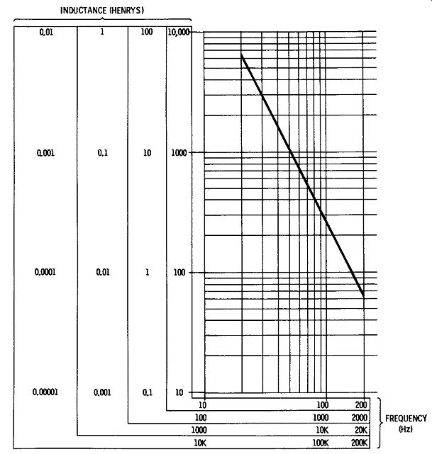
Fig. 13. Inductance chart.
SUBSTITUTION-TYPE CAPACITANCE METER
Small capacitances are accurately measured by means of the substitution process, since this method of measurement automatically compensates for stray capacitances in the test setup. It is advantageous to measure small capacitances (0.1 to 400 pf) at radio frequencies. Fig. 14 shows the circuit of a substitution-type capacitance checker operated at 1 MHz.
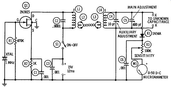
Fig. 14. Substitution-type capacitance checker.
This arrangement employs a 1-MHz crystal oscillator based on a 2N3823 FET ( Q1). The fix-tuned oscillator tank ( L1-C2) is link coupled to the resonant measuring circuit, which is composed of inductor L4, trimmer C4, variable capacitor C5, and unknown capacitance Cx connected to terminals X-X. A simple r-f voltmeter ( consisting of germanium diode X1, rheostat RS, microammeter M1, and r-f bypass capacitor C6) is connected across the measuring circuit as a resonance indicator. Both C4 and C5 are provided with calibrated dials reading directly in picofarads. The oscillator coil ( L1) and the measuring-circuit coil ( L4) are slug-tuned units ( L1, adjusted to 250 µh, Miller No. 20A224RBI; L4, adjusted to 60 µh, Miller No. 41A685CBI). L2 and LS are link-coupling coils which must be provided by the builder; each consists of 2 turns of insulated hookup wire closewound near the bottom ends of L1 and L4, respectively.
All fixed resistors are 1/2 watt. Capacitors C1, CS, and C6 are mica; C2 is silvered mica. All wiring must be short, direct, and rigid. Moreover, the wiring in the measuring circuit ( i.e., between L4, C4, C5, and terminals X-X) must be straight, solid No. 14 bus.
A fourth pigtail of the 2N3823 is internally connected to the metal case of this FET and must be grounded as shown, for shielding.
Total current drain is 12 ma at 15 vdc.
After the assembly has been completed and the wiring verified, the crystal oscillator must be initially adjusted:
1. Connect an r-f vtvm between ground and the top of LL
2. Close switch SL
3. Adjust the L1 slug for peak deflection of the vtvm. This slug need not be touched again except during routine recalibration of the instrument.
Next, initially adjust the measuring circuit: L Set variable capacitor C4 to half capacitance and C5 to maximum capacitance.
2. Set rheostat RS to maximum resistance.
3. Close switch S1.
4. Adjust the L4 slug for peak deflection of meter M1, reducing the resistance of RS if necessary to ensure a readable deflection. This slug need not be touched again except during routine recalibration of the instrument.
To use the checker:
1. Close switch S1, and resonate the circuit by setting C5 to maximum capacitance and trimming with C4 for peak deflection of meter ML Thenceforth, do not touch C4.
2. Record the capacitance setting of C5 as Ca,
3. Connect the unknown capacitance ( Cx) to terminals X-X by the shortest possible leads. This will detune the measuring circuit, and the meter deflection will either decrease or disappear.
4. Retune C5 to restore resonance, as indicated by peak deflection of M1.
5. Record this new capacitance setting of C5 as Cb.
6. Calculate the unknown capacitance: When long leads must be used to connect the unknown capacitor to the instrument, install the leads first ( in the same position they will take when the capacitor later is connected to them) and then perform Steps 1 and 2. This automatically compensates for the lead capacitance. Then connect the unknown capacitor to the far end of the leads and perform Steps 3 to 6 in the same manner described above.
When very small capacitances (0.1 to 10 pf) are measured, all readings ( Ca and Cb) should be taken from the dial of C4, and capacitor C5 should be used only to trim the circuit to resonance in Step 1. This step then consists of the following procedure:
1. Set C4 to maximum capacitance. Close switch S1, and trim with C5 for peak deflection of meter M1. Record this setting of C4 as Ca, and thenceforth do not touch C5.
IMPEDANCE METER
Fig. 15 shows the circuit of an impedance meter which employs a widely used principle of measurement: an a-f voltage is applied to an unknown impedance ( Z) in series with a calibrated variable resistor ( R), and the voltage drops ( Ez and Er) across Z and R, respectively, are checked separately with an electronic voltmeter while R is varied. When the voltage drops are equal ( i.e., Ez = Er), Z = R and may be read directly from the calibrated dial of the variable resistor.
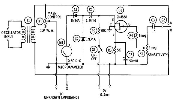
Fig. 15. Impedance meter.
In Fig. 15, rheostat R1 is the calibrated variable resistor ( 0 to 10,000 ohms) which is in series with the unknown impedance connected to terminals X-X. A signal voltage, derived from an external audio oscillator, is applied to this series combination through input transformer T1. The electronic voltmeter is composed of an a-f amplifier, based on a 2N4868 FET ( Q1), followed by a 2-diode rectifier ( X1, X2) and a d-c microammeter ( M1). When switch S2 is in Position A, this voltmeter is connected across variable resistor R1 and reads E .. ; when S1 is in Position B, the voltmeter is connected across the unknown impedance and reads Ez. The meter needs no voltage calibration, since it serves only to indicate reference points; the d-c scale of microammeter M1 may be used directly for this purpose. (It is only necessary to adjust R1 so that the deflection is the same for each position of switch S2; the magnitude of the deflection is inconsequential.) The input potentiometer ( R5) of the voltmeter circuit allows the meter to be adjusted for deflection near full scale to increase accuracy. Current drain of the circuit is 0.4 ma at 9 vdc.
All fixed resistors are 1/2 watt. Rheostat R1 is wirewound and must have a dial reading directly in ohms. Capacitors C1 and C3 are 100-volt plastic units; C2 is a 25-dcwv electrolytic. Transformer T1 may be any convenient unit having a 1:1, 2:1, or 3:1 turns ratio, and preferably should be shielded.
All wiring must be as short, rigid, and direct as practicable.
Overall shielding is desirable but not mandatory. A fourth pigtail of the 2N4868 is internally connected to the metal case of this FET and must be grounded as shown, for shielding.
Use this instrument in the following manner:
1. Connect an audio oscillator to the OSCILLATOR INPUT terminals (common test frequencies are 400, 500, and 1000 Hz), switch it on, and set its output to a level which will not saturate transformer TL
2. Connect the unknown impedance (Zx) to terminals X-X.
3. Set potentiometer R5 for maximum sensitivity.
4. Close switch SL
5. Throw switch S2 to Position A, and adjust rheostat R1 and potentiometer R5 for a deflection near full scale of meter ML Note the meter reading.
6. Throw switch S2 to Position B and note the meter reading.
7. Adjust R1 to make the deflection the same as it was in Step 5.
8. Throw switch S2 back to Position A, note the deflection and adjust R1 again, as in Step 7.
9. Continue this procedure until there is no change in meter reading as S2 is thrown back and forth between A and B.
10. At this point, read the value of the unknown impedance from the ohms dial of rheostat
RL HETERODYNE FREQUENCY METER
By means of the zero-beat method radio frequencies far into the spectrum may be spotted and measured with a calibrated low frequency r-f oscillator. This is made possible by zero beating between the unknown frequencies and harmonics of the calibrated oscillator. When a mixer and calibrated oscillator are combined for this purpose in one unit, the result is a heterodyne frequency meter.
Fig. 16 shows the circuit of a heterodyne frequency meter consisting of a 1 to 2-MHz oscillator ( Q1), an untuned mixer ( X1), and an a-f (beat-note) amplifier ( Q2). The oscillator employs a 2N3823 FET; the mixer, a 1N34A germanium diode; and the a-f amplifier, a TIS14 FET. The oscillator is of the Hartley type and is continuously tunable over the range of 1 to 2 :\1:Hz. The oscillator tank comprises coil L1, 365-pf tuning capacitor C4, and 50-pf trimmer capacitor C3. Coil L1 consists of 65 turns of No. 28 enameled wire closewound on a I-inch-diameter form, with a tap taken at the 20th turn from the ground end. L2 is a coupling coil consisting of 10 turns of No. 28 enameled wire closewound around the center of L1 and insulated from the latter.
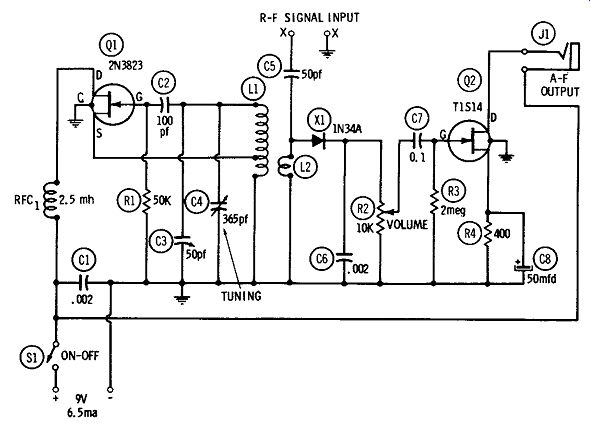
Fig. 16. Heterodyne frequency meter.
The oscillator output is coupled, through L2, into the diode mixer simultaneously with the unknown r-f signal ( coupled through capacitor C5). A beat note between the two signals is generated in the mixer and is transmitted to the a-f amplifier through coupling capacitor C7. The latter also serves to block the diode d-c component from the TIS14 gate. Magnetic headphones, plugged into jack J1, complete the TIS14 drain circuit and make the beat note audible. Other beat-note indicators, such as a vtvm, oscilloscope, magic-eye tube, or audio-frequency meter, may be used, provided J1 is shunted by a 2000-ohm resistor to complete the TIS14 d-c circuit.
The instrument draws 6.5 ma at 9 vdc. This value is constant for zero signal and maximum signal.
All fixed resistors are 1/2 watt. Capacitors C1, C5, and C6 are mica; C2 is silvered mica. C7 is a 100-volt plastic unit, and C8 a 25-dcwv electrolytic.
The oscillator tuning unit ( L1-C3-C4) must be stoutly built, and the entire oscillator stage should be enclosed in a grounded shield box. All wiring must be as short, direct, and rigid as practicable. A fourth pigtail of both the 2N3823 and the TIS14 is internally connected to the metal case of these FET's and must be grounded as shown, for shielding.
Main tuning capacitor C4 must be provided with a dial calibrated to read directly in frequency-1000 to 2000 kHz. One way to calibrate this dial is to feed an accurate, unmodulated r-f signal generator output into the R-F SIGNAL INPUT terminals, set C3 to midcapacitance, set the generator successively to as many frequencies as practicable between 1000 and 2000 kHz, and at each frequency set C4 to zero beat ( as indicated by headphone signal) and inscribe the C4 dial with the corresponding frequency. This calibration then may be checked more precisely by replacing the generator with a 100-kHz crystal oscillator, which will set up an accurate spot frequency each 100 kHz across the C4 dial. To standardize the oscillator in the future, it is only necessary to feed in the 100-kHz oscillator, set the C4 dial to its 1000-kHz point, and adjust trimmer C3 for zero beat. Since C3 needs no constant adjustment, it should be mounted inside the instrument case, where it will be safe from disturbance, and should be provided with a slotted shaft for screwdriver adjustment.
On second harmonics, the 1 to 2-MHz C4 dial covers 2 to 4 MHz, on twentieth harmonics 20 to 40 MHz, and so on. Similarly, on the second "subharmonic" the dial covers 500 to 1000 kHz.
HARMONIC-DISTORTION METER
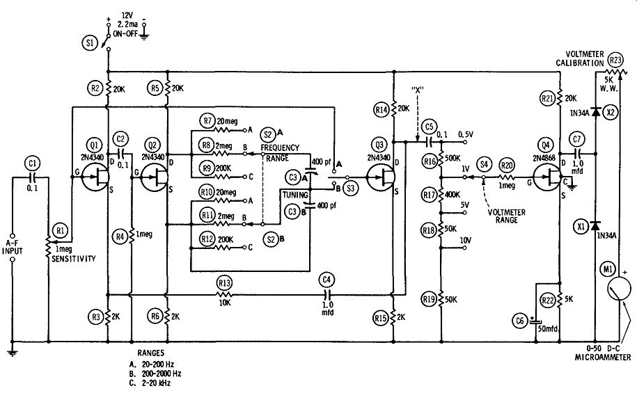
Fig. 17
A harmonic-distortion meter is convenient for measuring the total distortion of an audio amplifier, a component, or a network. A pure sine-wave signal is applied to the input of the device under test and the distortion meter is connected to the output. The meter is tuned to suppress the fundamental frequency of the test signal. The self contained electronic-voltmeter section of the instrument then is used to sample the output-signal voltage before and after the suppression.
The first voltage contains the fundamental and harmonics, whereas the second one contains only the harmonics ( distortion components introduced by the device under test). The total distortion therefore is the ratio of the second voltage to the first, and can be expressed either as a decimal or as a percentage.
Fig. 17 shows the circuit of a complete distortion meter employing these principles. This instrument covers the frequency range of 20 Hz to 20 kHz in three bands: (A) 20-200 Hz, ( B) 200-2000 Hz, and ( C) 2-20 kHz. Ranges are selected by double-pole, 3-position switch S2. The filter circuit is composed of range resistors R7 to R12 and dual 400-pf tuning capacitor C3. Within the amplifier comprised by FET's Q1, Q2, and Q3, this r-c network nulls sharply at the frequency to which it is tuned, and allows signals at other frequencies to pass relatively untouched in amplitude. The r-c network alone tunes broadly, but its response is sharpened by overall negative feedback around the amplifier through capacitor C4 and resistor R13. The voltmeter section comprises FET Q4, input range selector S4 and R16-R19, and rectifier-type microammeter ( M1- X1-X2). Total current drain is 2.2 ma at 12 vdc.
The amplifier section is based on three 2N4340 FET's ( Q1, Q2, Q3). This section is followed by an a-f voltmeter based on a single 2N4868 FET ( Q4). When switch S3 is in Position A, the voltmeter checks the signal voltage before the filter; and when S3 is in Position B, the meter checks the signal voltage after the filter.
All fixed resistors are 1 watt. Resistors R2, R3, R5, R6 to R12, and R14 to R19 must be rated at 1 percent. In an individual layout, R13 may need adjustment for sharpest null response of the circuit. Capacitors C1, C2, C4, C5, and C7 are 100-volt plastic units; C6 is a 25-dcwv electrolytic. Each section of the dual 400-pf tuning capacitor ( C3) has a built-in trimmer for initial adjustment.
After the instrument has been completed and the wiring verified, first the voltmeter section should be calibrated:
1. Set potentiometer R1 for maximum sensitivity.
2. Set switch S3 to Position A.
3. Set switch S4 to its 5-volt position.
4. Connect an accurately known 5-volt (rms) source to the A-F INPUT terminals.
5. Close switch S1.
6. Adjust rheostat R23 for exact full-scale deflection of microammeter M1.
The voltmeter now is calibrated on all ranges if resistors R16 to R19 are accurate. ( R23 need not be touched again except during routine recalibration). Next, the filter (tuner) should be adjusted:
1. Set potentiometer R1 for maximum sensitivity.
2. Set switch S2 to Position A.
3. Set switch S3 to Position B.
4. Set switch S4 to its 1-volt position.
5. Connect a high-grade audio oscillator to the A-F INPUT terminals and set it to 200 Hz at 1-volt rms output.
6. Set tuning capacitor C3 to minimum capacitance.
7. Close switch S1.
8. By adjusting the trimmers on C3A and C3B, tune the circuit for full dip (null) of the M1 deflection. ( Readjust R1 and S4, as required, for readable meter response.)
9. Tune C3 successively to various other frequencies down to 20 Hz, inscribing the C3 dial accordingly. The filter now will automatically be calibrated on the two other bands ( B and C) if resistors R7 to R12 are accurate.
Use of the instrument is straightforward:
1. Connect a high-grade sinewave audio oscillator to the input of the device under test.
2. Connect the distortion meter to the output of the device.
3. Set switch S2 to the appropriate frequency range.
4. Close switch S1.
5. Set switch S3 to Position A.
6. With switch S4 in the appropriate voltage position, adjust potentiometer R1 for full-scale deflection of meter M1.
7. Record this voltage as E1.
8. Set switch SS to Position B.
9. Tune capacitor CS for null, and set S4 to successively lower ranges for accurate reading of the voltage at null.
10. Record the residual null voltage as E2
11. Calculate the distortion percentage: D % = 100 _§_ E1
Under certain conditions, the instrument may be direct reading in distortion percentage, requiring no calculations. Thus, if E1 is 1 volt, this point may be regarded as 100 percent. The distortion percentages at null then may be read directly; e.g .. 0.01 volt = 1 percent, 0.1 volt = 10 percent, and so on.
A-F RF SIGNAL TRACER
The high input impedance of the FET makes possible for the first time a transistorized signal tracer which is fully competitive with the tube-type tracer. Basically, the signal tracer is a high-gain a-f amplifier which drives a visual signal-strength indicator and a speaker, and to which may be attached either a simple test probe for a-f input or a demodulator probe for a-m r-f input.
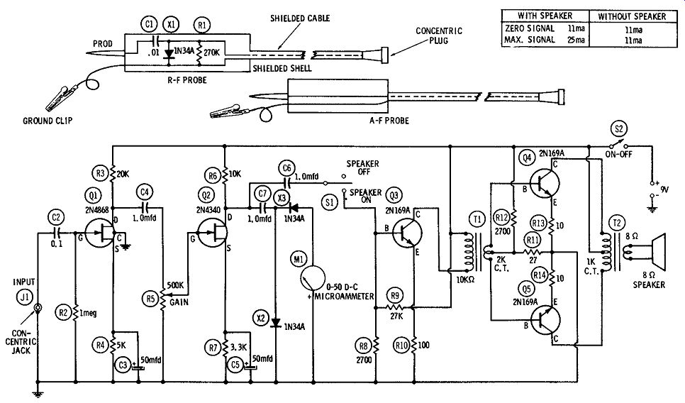
Fig. 18
Fig. 18 shows the circuit of a signal tracer employing two field effect transistors ( Q 1, Q2 ) and three NPN bipolar transistors ( QS, Q4, Q5). High sensitivity is provided by the front end, which consists of an r-c-coupled audio amplifier based on one 2N4868 FET ( Q1) and one 2N4340 FET (Q2). The a-f probe or r-f probe, as required, is plugged into this amplifier through concentric jack J1.
The front-end amplifier drives meter M1 through germanium diodes X2 and X3. This provides the visual indication of signal strength.
For aural indication of signal strength, a speaker is driven by the power amplifier consisting of a driver stage (based on a 2Nl69A transistor, QS) and a push-pull class-B output stage (based on two 2N169A transistors, Q4 and Q5). The latter stage delivers 100 milli watts to the speaker.
Switch S1 allows the speaker section to be turned off when the silent, visual indication provided by the meter is sufficient. At 9 vdc, the signal tracer draws a zero-signal current of 11 ma whether the speaker is on or off, and a maximum-signal current of 25 ma when the speaker is on and 11 ma when it is off.
All fixed resistors are 1/2 watt. Capacitor C1 is a 500-volt ceramic unit, while C2, C4, C6, and C7 are 100-volt plastic or paper units.
C3 and C5 are 25-dcwv electrolytics.
The layout is not critical; however, all wiring must be as short and direct as possible, to minimize stray coupling and interference.
For shielding, the entire unit must be enclosed in a metal box.
The instrument needs no calibration; since response of the meter section is linear, the readings of microammeter M1 may be taken directly as indications of signal strength, as long as the setting of gain-control potentiometer R5 is undisturbed during a measurement.
SENSITIVE LIGHT METER
The P-102 photo-FET is the basis of the sensitive light-meter circuit shown in Fig. 19. In this instrument, full-scale deflection of the O to 100 d-c microammeter ( M1) is obtained with only 5 foot-candles of illumination, when R1 is 10 megohms. Other ranges may be obtained by changing the value of this resistor-the lower the resistance of R1, the higher the range.
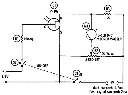
Fig. 19. Sensitive light meter.
Since there is some static drain current through the P-102, potentiometer R2 has been provided for setting the meter to zero. The operation consists simply of darkening the P-102 and adjusting R2 for zero deflection of meter M 1.
Current drain of the circuit is 1.2 ma at 9 vdc when the P-102 is darkened, and 2 ma when the light input deflects the meter to full scale.
Layout of the instrument is not critical. However, the P-102 has a lens in its nose, so this photo-FET must be mounted so as to point toward the light source. And since the gate electrode is internally connected to the case of the P-102, the FET must be mounted clear of wiring, chassis, and other components. Both fixed resistors are 1/2 watt, and potentiometer R2 is a wirewound unit.
GEIGER COUNTER
Fig. 20 shows the circuit of a simple Geiger counter based on one 2N4338 FET ( Q1) and one 2N4868 FET (Q2). Basically, this instrument is a high-gain r-coupled a-f amplifier followed by an a-c meter circuit ( coupling capacitor C4, germanium diodes X1 and X2, microammeter M1, and high-capacitance meter capacitor C6).
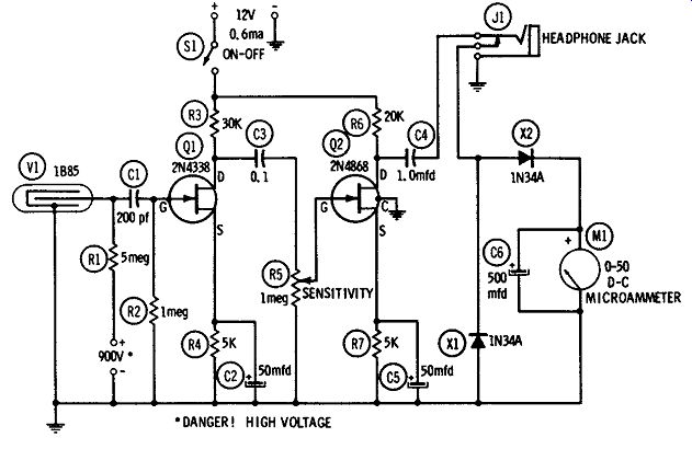
Fig. 20. Geiger counter.
A jack ( J1) also is provided for alternate use of headphones; and since this is a closed-circuit jack, withdrawal of the phone plug automatically switches the meter back into the circuit. Current drain is 0.6 ma at 12 vdc.
The amplifier receives its input signal from a Victoreen 1B85 G-M tube (V1) biased by 900 vdc (Less than 10 ma). This is a beta gamma particle counter. The type of self-contained supply selected for this high voltage will depend on the expense to which the builder can go. It can vary from three 300-volt photoflash batteries ( Eveready No. 493, or equivalent) connected in series to one of the factory-built, miniature, dry-battery-operated high-voltage modules.
Between these limits are numerous build-it-yourself units operated from flashlight cells ( 1.5 to 6 volts) of the transistor-oscillator, buzzer, and push-button-and-capacitor types. The ON-OFF switch in the high-voltage supply must be ganged with the instrument switch, SL All fixed resistors are 1/2 watt. Capacitor C1 is a 1000-volt ceramic unit; CS and C4 are 100-volt plastic, and C2, C5, and C6 are 25-dcwv electrolytics. All wiring must be short and direct. The gate electrode is internally connected to the case of the 2N4338 ( Q1), so this FET must be mounted clear of wiring, chassis, and other components. A fourth pigtail of the 2N4868 ( Q2) is internally connected to the metal case of this FET and should be grounded as shown, for shielding.
The count-rate range of the instrument may be determined by exposing the 1B85 tube to various calibrated radioactive samples, noting the corresponding deflections of meter M1, and graduating the scale of the meter accordingly.
[Note: This guide is based on Sams "FET Circuits", pub'd in 1961]