AMAZON multi-meters discounts AMAZON oscilloscope discounts
THE principles of induction heating were developed well be fore our modern high-power vacuum tubes were in general use. Dielectric heating, on the other hand, found its greatest impetus with the increased use of many kinds of plastics, and with the growing demands from the food industries which must process, preserve and prepare expanding quantities of fine products to serve more demanding and particular customers. Dielectric heating also has had to meet the challenge of mass production in the furniture industry, of great importance in electronics in terms of cabinets and speaker boxes. Not all cabinets can be made from plastics, but even there dielectric heating does its part. In either case, induction or dielectric heating, the requirements for high-frequency power are substantial.
First, let us examine briefly the principles of these two kinds of heating, and thereby learn their differences. After that we will take a look at the equipment producing the necessary energy for the processes, and discuss servicing and other problems.
Principles of dielectric heating
In dielectric heating, an object made from a nonconducting substance is placed in a dielectric field; in other words, in the field formed by the plates of a capacitor. The electrodes of a generator may vary in size and shape, but they will always constitute some form of capacitance. When a material is put into such a field, the field will penetrate all through it. There is no absorption and no deflection - and it goes right through.
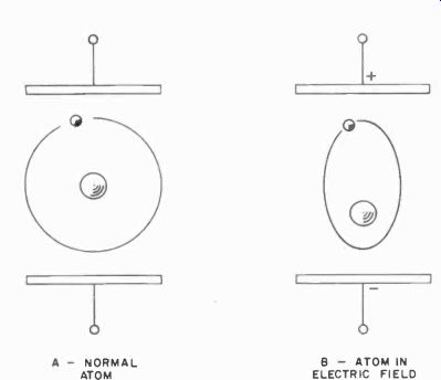
Fig. 301. Normal electron orbit of atom (a) is distorted by dielectric
field (b) created when voltage is applied to plates.
This means that all the molecules (and even the atoms) of the material are subjected to this field.
An atom consists of a nucleus with electrons whirling in orbits around it. Fig. 301-a shows a single nucleus with a single electron.
Of course, in practically all matter there is more than one electron in each atom. An electron is a negative charge. Placed near a negative electric -field charge, the electron will be repelled. If we let it meet with a positive-field charge, it will be attracted.
Thus if we place the atom between two plates and apply a strong electric field to them, the path of the electron will be distorted as a result of such forces of repulsion and attraction.
This is shown, greatly exaggerated, in Fig. 301-b. To accomplish this distortion of the electron path, we must apply a sizable amount of energy. This energy will be released when the electron snaps back to its original position when the field is turned off.
However, since the energy is now in mechanical form, it has no place to go except into another form of energy - heat.
This, somewhat simplified, is the principle of dielectric heating.
It follows that the heating which originates at the atomic level must be uniform throughout the material and very rapid. This is indeed the case, and the source of two of the major advantages of dielectric heating. It follows also that the more often we distort the electron orbit, the greater the amount of heat generated; thus frequency is important. As a matter of fact, unless you use very high frequencies, dielectric heating is ineffectual. (As you will see, this same relationship is not necessarily advantageous in induction heating.) There is, of course, a practical limit to the frequencies we can use for dielectric heating, but the limit is imposed by the equipment, not by the principle. This kind of RF can cook any material which is nonconducting, even hot dogs and steak. But since hot dogs are not entirely nonconducting, some other principles are involved, and we will discuss the cooking of food at microwave frequencies later.
Principles of induction heating Induction heating was discovered very early, when scientists noticed that the core of a transformer becomes warm, and some times very hot. This heating is due to two effects. First of all, there is a characteristic of magnetic materials which we call hysteresis. If we send a current through a coil which surrounds a ferromagnetic material such as iron or steel, we will magnetize this material. When we turn off the current, most of this magnetism disappears, but a small amount of it is left. We call this residual magnetism. To get rid of it, we must reverse the current and magnetize the metal in the opposite direction. This takes a certain amount of initial energy to remove the existing low-level residual energy. The energy required to remove residual magnetism can thus be considered a loss, and this is what we call the hysteresis loss. As with distorted atoms in dielectric heating, so with the magnetized domains in the metal. We have no place for the energy to go but into the metal as heat. One of the basic scientific laws of nature is that energy cannot be lost, only converted to some other form of energy.
At lower frequencies, this hysteresis loss, and the heat resulting from it, is very significant. As a matter of fact, the early induction -heating installations used only 60-cycle current, and many large electric furnaces operating on the induction principle still operate this way. These are not very likely to require the attention of an electronics technician, so we will not spend any time on the subject. But, remember, a lot of steel and iron is melted this way.
Above 10,000 cycles, the hysteresis effect, although still present becomes insignificant compared to another effect - eddy-current heating. Eddy currents are circulating currents created in a metal or any conducting material when it is placed in a changing magnetic field. The electric induction coil has a current produced in it when a magnet is moved in or out of the coil. You can try this easily yourself. Even a small magnet moved into the center of a coil of wire will create a deflection on a volt -ohmmeter in its sensitive ranges.
The surface of any metal object can be regarded as a coil. True, this requires a little imagination, but suppose that, as the result of the magnetic field, the current in the metal has a favorite path.
The current might prefer to run in a circle, and thus resemble a coil. In fact, this is about what happens. The changing magnetic field not only induces the current in the metal, but also determines the path the current will take. Many of these currents in various localities in the metal, added together, form a substantial transfer of energy, which again is converted directly into heat.
Since these currents occur in swirls and configurations reminiscent of eddies in a stream, they are called eddy currents. (They can be made visible by spreading the surface of the metal with very finely divided iron powder.) Note that in induction heating the object to be heated is placed in or near a coil, hence the name induction. (Eddy currents are induced currents.) Eddy currents are not confined to low frequencies and, again, there is no theoretical limitation to the frequency which can be used for induction heating. But, as before, there are practical limits to the frequencies used in induction heating, mostly due to the equipment and some due to Federal Communications Commission regulations. The FCC has the power to regulate all forms of radiation as to frequency and power.
And there is yet a third kind of limitation on the frequency used in induction -heating installations - the so-called skin effect.
As electrons are affected by electric charges in a field so they are also influenced by magnetic fields. In a TV picture tube, for example, a stream of electrons is sent out from a "gun," and are attracted by a strong charge (a very high voltage) on the anode of the tube. But to make the picture, this stream of electrons must be moved back and forth from side to side and from top to bottom like a paintbrush used to paint a wall. This motion of the electron beam is accomplished with strong magnetic fields created by the "deflection" coils. In other words, a magnetic field deflects the electrons from their original path.
This happens to electrons, no matter whether they are in a picture tube or in a metal wire. And, to make it even more insidious, the electrons will create their own magnetic field, which helps to deflect them. For moving electrons are like a moving conductor in a magnetic field - they will have a force exerted on them (as in a motor). The moving electrons can also be regarded as a current in a wire, creating a magnetic field by themselves.
The result of all of this is that, when the magnetic fields become stronger, as they do when the frequency goes up (the induced magnetic field in a coil contains more energy at high frequencies), the currents in a wire or any conducting material will be forced, by their own magnetic fields, to the outside of the material. This means that in induction heating, as we increase the frequency, the material will no longer be uniformly heated, but instead will be heated more thoroughly on the outside than on the inside.
This effect is used to control the depth of induction heating.
In fact, with this kind of installation we can do what we could never do with a flame applied to the surface of a metal object--we can accurately control the depth of surface hardening.
Induction heating is very fast; therefore, we can bring the out side of a sizable chunk of metal to a red-hot state while the center is still cold. If we do this fast enough, we can cool the outside again so fast that the metal has been made red-hot on the outside with out ever heating in the center. Or, induction heating can be a local effect. In other words, we can heat a part of the surface or the center by specially shaping our coil to create eddy currents in a particular way only, thus avoiding undesirable heat in the rest of the metal. We can also vary the depth of heat by varying the shape of the coil. These controls are accurate enough so that one piece of work could be heated to many different temperatures over its mass.
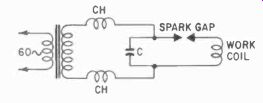
Fig. 302. Spark -gap induction generator has its operating frequency
determined by capacitor C and the work coil.
Induction heating at higher frequencies, since it does not depend on magnetic effects in the metal itself, can be applied to any metal and, in fact, any conductor. Thus glass, which we normally consider an insulator, becomes conducting when we first heat it to 600°F. We can then apply induction heating to it.
Induction generators
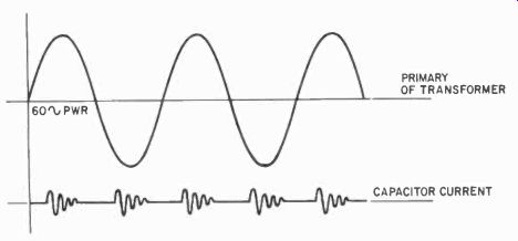
Fig. 303. High frequency of spark-gap generator is modulated at a 120-cycle
rate b the 60-cycle power line.
Many induction generators are extremely simple devices. That shown in Fig. 302 may look like a primitive generator - and indeed they stem from the days before high-power vacuum tubes were generally available - nevertheless, their operation has been so satisfactory that they remain in use today.
The generator consists of a power transformer, a spark gap and a tuned circuit, of which the work coil forms the inductance.
Whenever the voltage reaches a level sufficiently high to break down the gap, a damped oscillation takes place in the tuned circuit. This happens 120 times a second: 120 times per second the generator puts out a short burst of high-frequency current. Fig. 303 shows the waveform produced by this type of generator.
Generators of this type have been made to supply up to several hundred kilowatts. Notice the chokes, which keep the rf from entering the power transformer, and of course the gap itself keeps the coil from shorting the power transformer. The coil would present almost a direct short to the transformer, for induction -generator work coils have few turns made from heavy wire or bus bar. Although a single gap is indicated, there is actually a multiple gap, with as many as 50 to 100 gaps in series.
Gap spacing is critical and determines the breakdown voltage.
Usually the gaps are made from pure tungsten to resist excessive burning. Cooling with air is often used on the gaps.
The frequency of spark -gap generators is determined by the tank circuit. Thus, by changing the work coils or the capacitance in parallel with them, you can adjust the frequency to whatever is desired. However, remember that the coil values will change with the work -piece in place, and the adjustment for frequency must be made when it is properly placed in the coil. Also the heating of the work will change these values measurably, and a compromise between the cold and hot work -piece must be made.
Although the depth of heating is affected by the frequency, this is not an extremely critical affair, except in some special cases where great pains must be taken for frequency accuracy.
The only serious problem likely to arise with the spark-gap generators is burning of the gaps. These must be periodically inspected and serviced, or replaced. In many cases, honing the gap surfaces will restore them for another tour of duty. Gap clearance must be carefully adjusted, and this is a critical job.
Even a small change in each gap spacing would change the total gap distance considerably, and thus would affect the output of the generator. In fact, the accepted way of adjusting the current through the work coil is to change the gap, so that the spark will persist over more or less of the half -sine wave from the power transformer. The earlier the gap breaks down, the longer it persists, and the greater the average power produced by the generator.
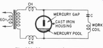
Fig. 304. Mercury under pressure prevents vapor from forming and making
the arc uncontrollable.
Because gap problems are continual with such generators, more modern versions of the spark generator use mercury-arc spark gaps which last for a very long time. The principle is shown in schematic form in Fig. 304. It is essentially the same kind of generator with the simple difference in the gap. Although the one shown is a single gap, there are also dual gaps with two electrodes in the chamber. Essentially, the gap is a cast-iron chamber with a pool of mercury in the bottom. The chamber is filled with hydrogen gas under low pressure. Without the added pressure, the chamber would soon be filled with mercury vapor, and the duration of the arc might become uncontrollable. The electrodes are specially-tipped copper rods which can be raised and lowered for gap adjustment. The hydrogen above the pool is sometimes stationary and sometimes is circulated continuously from a large tank. These mercury-arc type generators are available up to about a 40 kw rating.
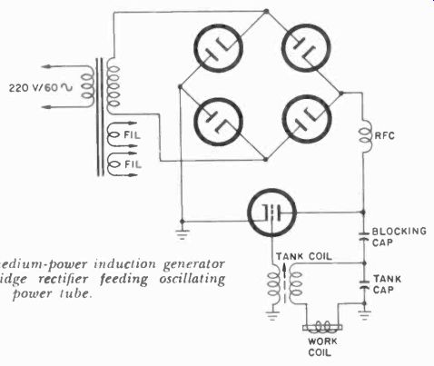
Fig. 305. Simple medium-power induction generator has unfiltered bridge
rectifier feeding oscillating power tube.
Frequencies used with these generators, as well as the air -gap type, vary with their applications. For melting purposes, frequencies from 20 to 80 khz are used, and for other applications the frequencies may go as high as 400 kc. Such high values are primarily used where only surface heat is needed, as in case hardening and some kinds of brazing. Maintenance problems with these mercury -arc generators will be minimal, consisting mostly of keeping the electrode tips clean and adjusted and the work -coil connections free of corrosion.
When the triode power tube was developed, one of its early applications was in induction -heating generators. Fig. 305 shows a typical induction-heating generator of moderate power. Notice that there is a power supply with a full -wave bridge rectifier but no filter. In communications, we would not want to tolerate 60-cycle modulation (or, in this case, 120 cycles) of the generated rf, but in heating, it is of no concern.
As you can see, the oscillator is a simple one with a tuned plate load and a feedback coil, while the work coil is part of the plate tank circuit. In some cases, the work coil makes up the entire plate inductance.
Since the work coil directly surrounds the heated object, the coil will become quite hot itself, if only from the radiated heat from the work piece. For this reason, the work coils almost al ways consist of tubing, with cooling water circulated inside of them, or of a coil with a special copper cooling tube welded parallel to the coil proper. This makes the connections of the water-cooling system and the tank somewhat complicated. Since the bore of these tubes is not large, and the cooling efficiency depends on the amount of water that can be sent through them, the opening must be kept clear of deposits. For this reason, such an installation will often include a water softener, or a large sup ply of distilled cooling water which is cooled and reused. Such a system is often a completely closed one to avoid contamination of the cooling water. This type of cooling requires insulated cooling supply lines, and part of the maintenance procedure is to see that these lines are in good condition.
Problems with this type of generator revolve generally around the failure of the tubes, either the rectifiers or the oscillator.
Such troubles are easy to locate. When the ac voltage on the rectifier plates is adequate but the dc is sagging, the rectifiers are due for replacement. When the dc voltage is adequate but the oscillator fails to produce sufficient current, the tube may be ready for replacement. Most generators have meters in both the plate and grid circuits, and poor operation shows up immediately on these meters. Of course, other sources of similar trouble must be eliminated for, example, poor connections to the work coil, etc.
Remember when "poking around" in this type of generator that you are probably dealing with potentials up to about 10,000 volts, so be extra careful and take all the necessary precautions.
Check points are generally brought out to external measurement terminals in any case, so that you need not get into the "hot" generator at all.
Since the work coil is always external to the generator, the circuit of Fig. 305 is a preferred one because it avoids high-voltage dc on the work coil. This does not mean that it is safe to touch the coil with the generator on. Very bad RF burns could be the result. Also, metal objects such a wristwatches, rings or tools should not be brought within the field of the generator--they would promptly heat, and perhaps melt. Nor is it wise to put test instruments in the vicinity of a "hot" coil; the plastic case may survive but the "works" may end up as a molten ump of metal inside the case.
The essential part of the generator, the work coil, may not look much like a coil at all. Fig. 306 on this and the following page show some typical work coils for induction generators. These coils are shaped and sized to accomplish a precise heating job, whether this be an even, or local, heating problem. Notice the cooling tubes provided to keep the coil itself from becoming red-hot. Fig. 307 shows such an induction generator in operation for the hardening of automotive transmission parts. In the automotive industry, such generators are extremely common.
For higher powers, two or more oscillator tubes are often wired in parallel. The power supply then is likely to become a three-phase job. In this way, powers of hundreds of kilowatts can he obtained. The three-phase power supply is typical of one we will discuss under dielectric generators.
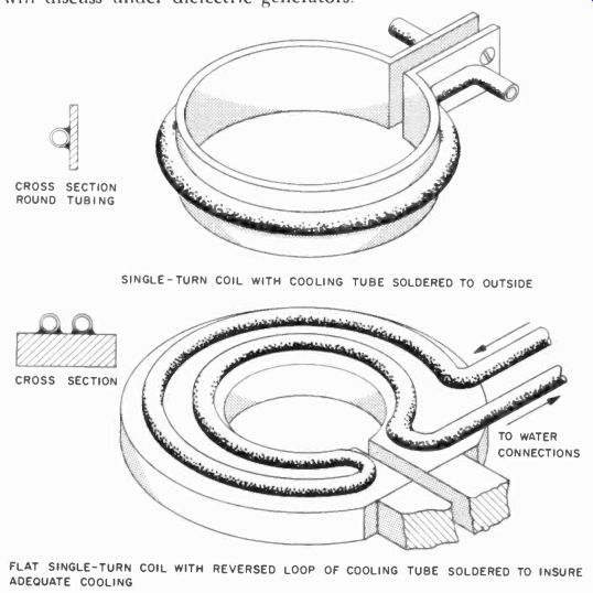
Fig. 306-a. As generator power increases, cooling problems also increase.
SINGLE-TURN COIL WITH COOLING TUBE SOLDERED TO OUTSIDE; FLAT SINGLE-TURN
COIL WITH REVERSED LOOP OF COOLING TUBE SOLDERED TO INSURE ADEQUATE COOLING
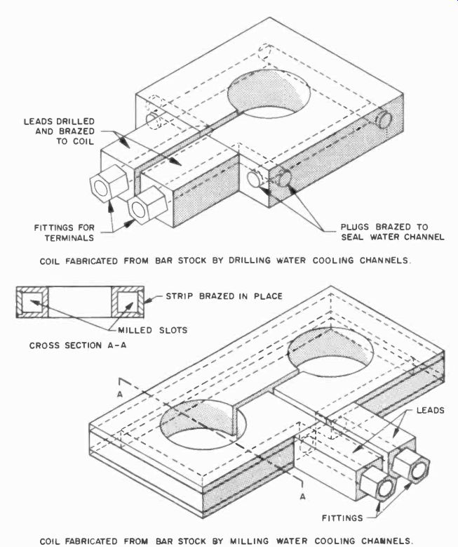
Fig. 306-b. Water-cooled coils of this type require considerable machine
-tool work. COIL FABRICATED FROM BAR STOCK BY DRILLING WATER COOLING CHANNELS.;
COIL FABRICATED FROM BAR STOCK BY MILLING WATER COOLING CHANNELS.
When checking the meters on the equipment, it is well to re member that too little plate current shows lack of emission. Too little grid current would show either low emission, poor tuning or other maladjustment in the circuit. Too much grid current with low cathode current might indicate that the tube has be come gassy.
These tubes are often so large that special setups have to be made to test them. It is, therefore, generally necessary to judge the condition of the tubes in the actual working circuit. Tubes should last up to 2,000 hours of operation. Beyond that not much can be expected, although many tubes will last longer. At 1,500 hours, replacement of the tube should be considered.
If the equipment is used intermittently, it will be better to arrange for the filaments to be kept hot. A large tube (or even a small one) will be damaged more easily and show more wear from being turned on and off many times than from proper use.
Remember also that most equipment using large tubes has a delay timer which prevents the plate voltage from being applied to the plate before the filament or cathode is properly heated, since this could seriously damage the cathode. Many of these large tubes (as well as the work coils) are water-cooled and proper maintenance of the cooling system is absolutely essential.
Repair of large induction generators is usually not difficult, for, in essence, these are very simple devices.
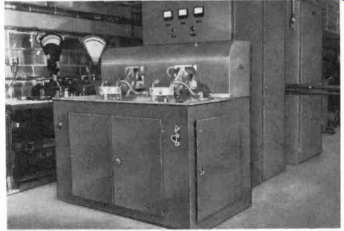
Fig. 307. A 25-kw induction heater is used to harden valve stems. (General
Electric Co.)
Dielectric generators
Dielectric generators are essentially similar to induction generators with one important difference. In the former the work is placed in the tank capacitance while in the latter it is placed in the tank inductance. With the work inside the capacitor which is part of the tuned circuit, the chances are that as the work heats up, there will be a considerable change in the frequency of the generator. Fortunately this is of little importance in dielectric heating except that a drastic change of capacitance may require that we change the timing of the generator, and leave it on longer or shorter for a particular kind of work. This timing is always established by experiment in any case and, once it has been set for a particular type of work, it can usually remain at that adjustment.
Basically, there are two kinds of dielectric generators, the direct loaded type, in which the electrodes are actually a part of the tank circuit, and the impedance -matched type. In the latter we take the energy out as we would in any tank circuit by a matched separate tank, with the work piece, the electrodes and the coupling coil tuned to the generator frequency.
The impedance-matched generator has some advantages. In the first place, it avoids the possibility of having dielectric break down of the work damage the generator, since the matching coil has only a few turns and, in effect, constitutes a current transformer. Second, it is easier to remove the electrodes from the generator and operate them at a remote point. And, third, it affords a simple way of adjusting the output power of the generator by changing the coupling of the two coils.
Fig. 308 shows a typical direct-loaded generator and Fig. 309 a typical impedance -matched type. Note again the absence of any filter capacitors. However, the generator will be supplied with a filtering system on the primary or secondary side of the transformer for the purpose of removing any high-frequency energy from the power -line connection. Otherwise, the power line would act as a radiator and could cause a great deal of interference. The FCC has set up strict rules about this, as we shall see.
Dielectric generators come in many shapes and sizes, and for many purposes. Fig. 310 shows a generator inside a bag -sealing machine used to seal plastic bags such as are used for peanuts, etc. Fig. 311 shows a machine specially designed to seal seams on plastic swimming pools on the job. In this case, it has to be an impedance -matched type, since the electrodes are remote from the generator. Similar generators are used in furniture shops to dry glued joints. Where formerly a chair would have to remain clamped for as long as 24 hours after gluing, now the glue can be made to set in minutes, thereby greatly increasing the production of all kinds of wood products.
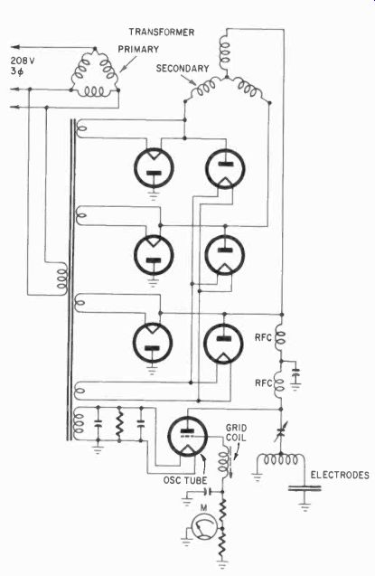
Fig. 308. Simplified schematic of a typical direct-loaded dielectric generator
has dc supplied by a three-phase full -wave rectifier.
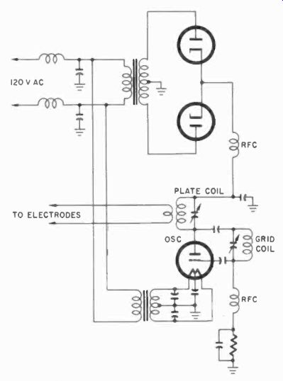
Fig. 309. Simplified schematic of a typical impedance -matched dielectric
generator.
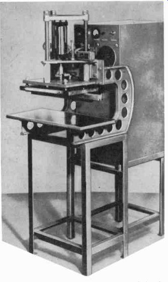
Fig. 310. The working surfaces of most dielectric generators are designed
for specific jobs. This one seals plastic bags.
Sometimes a generator will include a small fluorescent tube which will light when the generator is on, due to ionization of the mercury vapor in the tube when exposed to the field of the generator. This is a positive indication that the generator is on, and a signal to the operator to keep his hands out.
A similar indicator can be made by the technician. Fig. 312 shows a simple one consisting of a small neon bulb on a rod, and a battery. The small battery is not quite sufficient to fire the tube but, as soon as the tube is moved into the field of a generator or transmitter, the resulting ionization will light the bulb and the battery will intensify the glow. This makes it a very sensitive probe for detecting stray fields, and is strongly recommended when checking a dielectric or induction -heating installation, since exposure to an intense field can be dangerous.
The electrodes that are provided with the generators may vary considerably in shape and size. Fig. 313 shows several unusual shapes in use. To heat large areas such as are encountered in the lamination of plywood sheets or plastic on plywood, large electrodes are needed. To avoid excessive capacitance from such large electrodes, they are broken into strips, separated by about their own width. This will do an adequate heating job, particularly if the strips on the opposite side of the work alternate in location.
Ordinary dielectric-heating generators have been used in food preparation. One example is the hot-dog cooking arrangement in a vending machine, shown in close-up in Fig. 314. The hot dog is actually passed through the coil of the push-pull generator, but the effect is the same as in dielectric heating. However, this is an unusual installation and you will probably not encounter too many of this type.
The repair and maintenance of dielectric generators is similar to that of induction generators. Values of tube currents at the proper voltages are your most important indicators of the proper functioning of the generator. In the case of impedance -matched generators, tuning is very important. This will sometimes be adjustable from the outside, and in other cases will require the movement of taps on the coil inside the generator.
Dielectric generators are used for producing mass quantities of identical or very similar products, and the final criterion of how well the generator is doing its job is the shape and condition of the end products.
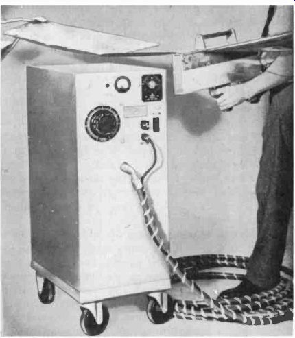
Fig. 311. This impedance-matched generator uses a long cable to take the
work head to the job.
Microwave cooking
Radar cooking is a process similar to those we have just discussed, except that a much higher frequency is used. In radar cooking, we deal with a frequency of 2450 mhz - the 10 -cm region.
The power in these areas must be generated by special tubes, and mostly the manufacturers use magnetrons. Klystrons have been used in some commercial installations.
The principles of microwave cooking are actually somewhat in question. Some of the effects are due to dielectric and some to induction heating. No electrodes are used. The material, in this case usually meat of some kind, is placed in front of a waveguide, and a rotating vane is used to make sure all of the material is exposed to the same amount of radiation. In this way, both the electrostatic and magnetic fields come into play. Where the material, such as some of the fats, is an insulator, there will be dielectric effect.
Where it is a conductor, there will be induction effects. There are borderline regions in which both effects will show up. however, there is the possibility that there may be other factors involved, for example, resonance of some sort. Although it is not yet fully understood, microwave cooking is very effective; a portion of meat which would take many hours to cook ordinarily can be cooked in minutes by microwave.
Ultrasonic generators Although the principles of ultrasonic generation have long been familiar and applied to a limited extent, their application has jumped enormously in the past 5 or 10 years with the development of new kinds of efficient and relatively inexpensive transducers. Thus, where formerly the ultrasonic generator was mostly used in depth finders and similar low-power applications, now there is a rapidly expanding range of application of ultra sonic devices.
Ultrasonics is now so widespread a whole book could be written on the subject. It is used small parts, washing with out soap or detergent, thickness gaging, flaw detection, medical diagnosis, agitation, homogenization, machining of extremely hard parts, dental drills, remote controls and many, many other applications. We will discuss only the principles involved and the generators needed to provide the ultrasonic power, and from this you will be able to recognize the necessary service equipment and procedures to be used in maintenance and repair. Necessarily our account will be limited.
Basic transducers
There are in ultrasonics three basic kinds of transducers. The third, a new material, is used only for low power applications. The principal power transducer until recently was the magnetostrictive type. This depends on the principle that a magnetized metal rod, when subjected to a varying magnetic field in addition to the magnetizing force, will undergo contraction and expansion in length due to the changes in magnetic field strength. Conversely, such a rod will also respond to ultrasonic waves striking it by creating (when magnetized) a voltage in a coil surrounding it in proportion to the ultrasonic signal impinging upon it.
The frequency at which a magnetostrictive transducer rod will vibrate is related to its dimensions (length and diameter) and to the material of which it is made. Thus a rod made from a cobalt alloy has different characteristics from a nickel rod (it will change length much more) but is more difficult to produce. In general, magnetostrictive transducers are not particularly efficient, and this has been one of the factors holding back development. In addition, due to the dimension tie-in, magnetostrictive transducers are limited in usable frequencies to the near -audio range, from about 20 khz to 50 khz, whereas other kinds now can be used practically, up to several megacycles and, in some special laboratory applications, have been operated successfully up to as high as 10,000 megacycles (sound waves!!)
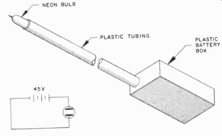
Fig. 312. High -frequency field "sniffer" uses battery to make
it more sensitive.


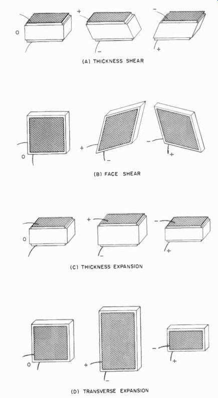
Fig. 315. Piezo-electric crystals distort when subjected to a dielectric
field. This change of shape is dependent upon the crystal type, cut and
field polarity. (A) THICKNESS SHEAR (B) FACE SHEAR (C) THICKNESS EXPANSION
(D) TRANSVERSE EXPANSION
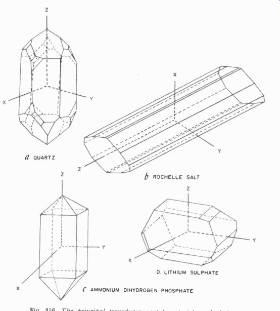
Fig. 316. The principal transducer crystal materials and their crystallographic
axes. a QUARTZ; Z b ROCHELLE SALT ; D. LITHIUM SULPHATE; C AMMONIUM DIHYDROGEN
PHOSPHATE
Quartz crystals of a special cut have also long been popular.
However, a quartz crystal which will transmit sufficient physical energy must be relatively large (or a number of them must be used in parallel) and is economically unfeasible due to the prohibitive cost of quartz crystals of this type.
Fig. 315 shows different ways in which the various kinds of crystal cuts will distort when electrical fields are applied. Trans verse shear is obtained from a 0° X-cut of Rochelle salts, and a 45° X -cut gives double transverse expansion (shown exaggerated in Fig. 315). The 0° and 45° Z-cuts of ammonium dihydrogen phosphate, a modern synthetic transducer, give the [...missing ]In gaging or in detecting flaws in solid materials, the transducer is brought into direct contact with the material. In this case, the transducer is often used both as a transmitter and receiver, and a change in echo signal can be recorded and interpreted as some flaw.
What kind of generator is needed for such ultrasonic applications? It depends a great deal on the application since frequency and power requirements vary widely. Most cleaning generators for small parts do not need more than several hundred watts of power, but some larger installations run into several kilowatts.
Frequencies also vary, but most cleaning operations are carried out between 25 and 50 khz although in some cases it may be as high as 1 mhz. The value depends on the manufacturer and his experience with that particular application. Some operations can be carried out at several frequencies, whereas others are effective only at a particular one.
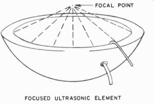
Fig. 317. Work placed in the locus will receive maximum ultrasonic energy.
FOCUSED ULTRASONIC ELEMENT
One typical generator is shown in Fig. 318. This is a relatively low -power unit such as might be used for an ultrasonic soldering tool. In this particular example, a special magnetic coil, coupled to the magnetostrictive transducer through a metal bar, provides the necessary feedback for oscillation. More often the feedback coil is wound on the transducer itself. However, here a special condition exists in which the frequency of the generator can take place in multiples and submultiples of the transducer's natural frequency, depending on the coupling between the work and the transducer. This allows the automatic adjustment of the system to the natural frequency of the entire system of transducer and bit. This frequency changes with the great variation in temperature and external loading by the soldering bit, which is attached to the transducer laminations. In this example, the transducer laminations are made from a cobalt alloy.
Ceramic transducers are not frequency selective as the crystal types are. Usually the ceramic type is operated well below its natural frequency or well above it, depending on size.
There is little basic difference between this type of generator, which can be made for the range from 50 khz to 1 mc or more, and the familiar class -C power amplifier in transmitters.
Measurements
Gaging and measurements are a little different. The power requirements are much less. When the moving molecules in a dense piece of matter reach the end of that material and find a vacuum or just air, few of them find gas molecules to push so they bounce back against other molecules in the solid and start a wave back from the boundary layer. If we adjust the frequency of the original wave so the time it takes for it to travel out and back is exactly half a cycle or a multiple of it, we have a 180° phase shift for regeneration. Any deviation from this precise dimension would immediately show up as an improper phase shift. The diagram in Fig. 319 shows the basic circuit of this kind of gaging apparatus.
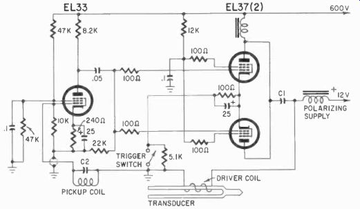
Fig. 318. Generator for ultrasonic soldering tool.
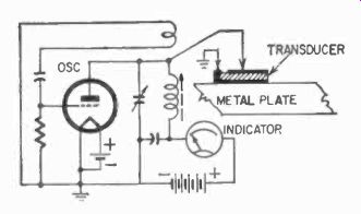
Fig. 319. Basic circuit for an ultrasonic thickness gage.
FCC rules, which apply to all industrial heating equipment, are also applicable to ultrasonic generators. Fortunately, the latter are much easier to shield, since only the crystal need be outside the case and works just as effectively inside a shielded case of its own.
Miscellaneous generators
There are a number of other applications of electronic generators and oscillators, but they do not present any new aspects of electronics so much as they illustrate new uses of the medium.
Low power oscillators are used in instrumentation and telemetering, control systems and high -frequency welding, to mention just a few.
Basically all rf generators operate on the same principles. The two criteria for oscillation, a gain of more than one and in-phase feedback, are valid in all cases.