AMAZON multi-meters discounts AMAZON oscilloscope discounts
IN all industrial generator installations, careful attention must be paid to the possibility of creating radio interference, not only as a matter of good public relations, but also because of strict regulation by the FCC. The FCC rules for industrial generators are contained in Part 18, "Industrial, Medical and Scientific Uses of Radio." Part 18 sets aside four frequencies for the operation of industrial heating installations without a license: 13.553 to 13.566, 26.960 to 27.280, 40.660 to 40.700, and 2400 to 2500 mHz; (2.4 to 2.5 giga hz) other frequencies may be used however, provided no interference is radiated.
Even in the assigned frequency bands, harmonic radiation must he carefully suppressed so that not more than 10 pV per meter signal can he detected 1 mile from the equipment. "Per meter" means a signal which can be picked up on an antenna 1 meter (a little over 3 feet) long. This figure also applies to equipment which operates at other than the assigned frequencies, but here the fundamental must also be suppressed to that extent. Further more, the same 10-pv-per-meter limitation applies at a distance of 50 feet from the power line to the equipment. This is to prevent the power line from acting as a radiator (antenna) for those frequencies.
All equipment must be grounded, and this often reduces radiation too, particularly if the equipment is housed in a metal cabinet.
However, more drastic shielding is often necessary. In some cases, the entire room may have to be shielded, an expensive operation.
Shielding has its own particular requirements. For example, if the shielding material is a mesh, care must be taken to use a small enough mesh. Any openings greater than a quarter -wave length would be like no shielding at all.
Doors and windows must be covered with the shielding material, and here particular attention must be paid to bonding the various sections. Usually a bonding strap is used every foot or so. At the hinge side of a door, flexible braid is used; for the other side of the door, a pressure contact must be made.
If commercial equipment is installed, the manufacturer usually contracts to install the generators in accordance with all applicable FCC requirements, and guarantees the installation will not generate objectionable interference.
Rf heating interference can be detected first of all at close range with a probe, and secondly with a shortwave receiver. If, during the tests, the equipment is turned on and off in a particular pat tern, it will not be difficult to find the 120 -cycle modulated signal and identify it. Equipment manufacturers often maintain completely equipped detector trucks which can check with sensitive calibrated equipment for all interference over the required distances. For most purposes, a sensitive communications receiver with adequate frequency coverage can give a reasonable indication of whatever interference may be generated. Since these frequencies are close to some TV intermediate frequencies, this is where most of the trouble is found.
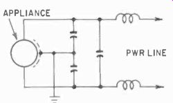
Fig. 401. A filter of this type will remove the more stub born types of
interference.
Although its monitoring stations continuously check the various frequencies used, the FCC usually does not take action until a complaint is received. The FCC has considerable power, and by legal action can shut down factories if the owners are uncooperative about correcting violations.
Interference sources
Many types of industrial equipment can create interference, even a simple motor or generator commutator. Part of industrial electronic servicing is the elimination of such interference, no matter what its origin.
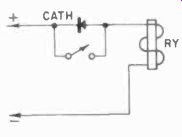
Fig. 402. Rectifier will reduce switch contact burning when the coil field
collapses.
Generally, interference is transmitted over and radiated by power lines and is quite easily controlled, once it is located. One simple way to locate a source of interference is to switch off one device after another in a plant, to determine if it is the trouble maker. It is best to wait until night when the plant is shut down, or on weekends, and turn on one machine after another until the offending equipment is located.
Fluorescent, mercury-vapor or cold-cathode lights are notorious sources of radio interference. Any kind of a gas -discharge device, such as a thyratron, is next on the list of suspects. Consider all devices which may continuously or intermittently create sparks--switches, thermostats, commutators, rotary converters, vibrators or even loose connections in any equipment. Static charges on belts and pulleys may be as responsible as electronic precipitation equipment, which electrostatically removes dust from the air or soot from smoke. Any prime mover such as an internal combustion engine may be causing interference with its spark plugs.
If these simple methods fail to locate the trouble, try using a receiver with a loop antenna. The interference may not be located within the plant but be generated by something else near by. The swiftest way to demolish accusations of interference is to locate its true source. With a loop-equipped receiver, converge on the suspected location from several directions or take "bearings" on it from a circle around the area. This should quickly locate or even pinpoint the interference source. For example, high voltage insulators in substations as well as on power poles, when dusty or wet, may create a great deal of noise in radios. If power line equipment is responsible, it must be serviced by the utility company.
The simplest interference filter is a capacitor across the terminals of the offending device, which effectively bypasses the rf to ground through the powerline. Such very simple filters have, however, one serious disadvantage. With a particular inductive load and a particular size capacitor, the interference may be increased because the circuit may become resonant to the fundamental or some harmonic of the main interference frequency.
In that case, more effective means such as the filter shown in Fig. 401 must be used. Here inductors as well as capacitors have been used. The inductors can be rf chokes wound from wire heavy enough to carry the load current, and the capacitors should be at least .05 pf and the proper peak-to-peak voltage rating.
In a 120-volt ac circuit, the capacitors must have a working-volts rating of at least 250; in a 220 -volt circuit, at least 380. Coils must also be properly insulated for the voltage, and the entire assembly housed in a metal box or cabinet which meets safety codes. The filter of Fig. 401 can be doubled and tripled to make it more effective, but in the majority of cases the single section is adequate.
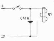
Fig. 403. Rectifier across coil shorts the counter-emf generated by collapsing
field around coil.
Relays are another possible source of a great deal of interference.
When the circuit to a relay coil is broken, the voltage across the coil tends to rise sharply due to the field remaining around the coil. This voltage appears across the contacts which open the circuit, and thus will cause arcing. This can be suppressed usually by shunting the contacts with a capacitor but, again, the capacitor, if not of exactly the right size, may make matters worse. Too large or too small a unit may make the arcing worse.
A rectifier across the contacts will be more effective (Fig. 402).
Since the voltage built up by the collapsing magnetic field of the coil is opposite to the normal flow of current, this generated current will flow through the rectifier when the contacts are opened, but the normal coil -energizing current can not.
Another method is to shunt the coil itself with the rectifier (Fig. 403). To the voltage generated by the coil, the rectifier will look like a virtual dead short, and the field will not build up sufficient voltage to arc across.
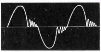
Fig. 404. Waveform generated by repeated extinction and striking of arc
within the fluorescent lamp is at frequency much higher than that provided
by the power line.
A capacitor across the coil has a similar effect. But, to be really effective, the capacitor must be very large and then the relay operation will be slowed, since, to attract the armature the capacitor must be charged. To break the contact, the capacitor must be discharged first, as the energy stored in it will continue to hold the armature. Thus a large capacitor across a relay coil can be used only when the speed of the relay is not critical.
One of the worst offenders in causing radio interference is the fluorescent lamp and its cousins the cold -cathode and mercury vapor lamps. During an ac cycle, the gas -discharge lamp, which includes the fluorescent lamp, is not on continuously. When the voltage across it drops low enough, the lamp will extinguish; when the voltage gets high enough again, it will arc across to light.
However, our slowly reacting eyes, helped by the persistence of the fluorescent powders (coating on the inside of the glass that continues to glow between cycles) makes the lamp appear to stay on.
Fig. 404 shows the waveform which occurs at the terminals of the fluorescent lamp. When the voltage drops low enough, the lamp will extinguish. But because the load across the ballast is now reduced, for a very short instant the voltage will rise again.
Thus the lamp may "strike" again and become conducting. But the voltage is still falling, and the lamp goes out again. And so, in rapid succession, at the start and end of each cycle, the lamp will "flicker" on and off very rapidly a few times. This is equivalent to radiating a very high frequency, and is a serious cause of radio interference.
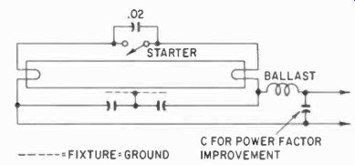
Fig. 405. Capacitor across switch reduces one type of interference while
the capacitors grounded to fixture remove most of the hash.
Although filters can be constructed to remove any such rf from the power line to the lamp, it is almost impossible to build a shield around the lamp that will not let the arc in the lamp itself "broad cast" the rf. For this reason you will find few fluorescent lamps in communications installations as they must be contained in a special, very expensive fixture.
To remove rf from the power line, we can use the method shown in Fig. 405. Here only capacitors have been used but, if the interference is serious enough to warrant it, chokes may have to be added. Cold -cathode and the so-called "instant -start" fluorescent lamps as well as the "slim -line" types do not use a heated cathode to start, and must therefore be lighted with much higher voltages.
Remember that the capacitors must also be suitable for such high voltages. For 8 -foot slim -line lamps, the open -circuit voltage may be as much as 1,500 rms and require 2,500 -volt capacitors. For cold -cathode lamps, the voltage may run more than 5,000 volts, open -circuit.
Since such high voltages are always obtained from transformers, the easiest method is to insert a line filter in the transformer primary circuit. Even with this all the wiring between the lamps and the transformer secondary windings still radiate considerable interference. In one church in California, radiation was so severe that television reception for several miles around was impossible when the church lights were on. Needless to say, corrective action was taken quickly.
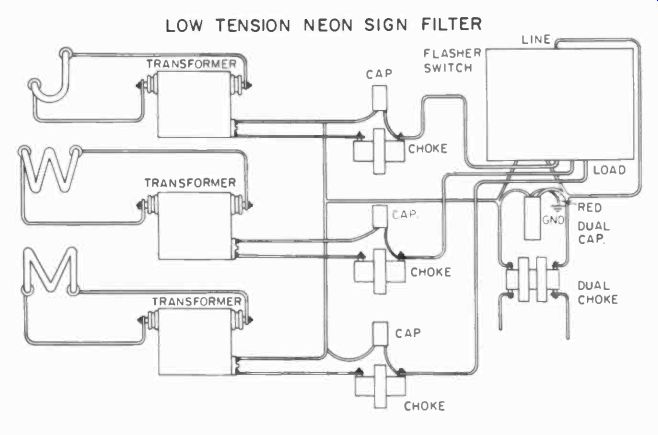
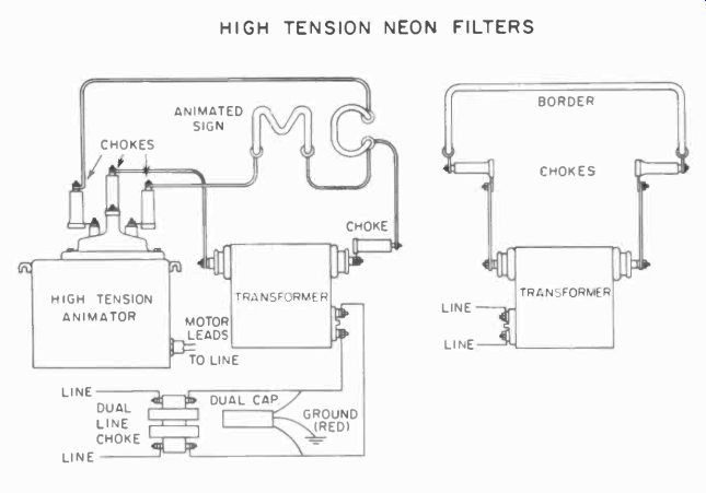

Fig. 406. Filters for neon signs help reduce interference from that sourer.
LOW TENSION NEON SIGN FILTER ; HIGH TENSION NEON FILTERS
If the wires from the fixture to the lamps are properly enclosed in a grounded metal conduit, interference is minimized. But this does not eliminate the problem of interference from the lamps themselves. There is really no easy answer to that problem, except to use special fixtures.
Neon signs are another source of radio interference. Their voltages are even higher, often going up to 30 kv, that makes the use of capacitors impractical. Fig. 406 shows two methods of reducing radio interference. These are only partial remedies; the lamps themselves are also radiators. Sometimes, in addition, rf filters in the primary of the transformer may help. If the tubes are actually mounted inside letters or figures made of sheet metal, as they are in many signs today, the interference even from the tubes themselves will be considerably reduced if all the sheet metal is properly grounded.
While not a problem in fluorescent lamps, the connections to neon lamps are apt to cause interference through corona discharge at the voltage peaks. Corona is the electrical discharge of energy resulting from ionization of the surrounding air. It will take place from any sharp point which is at a high voltage potential. It is not necessary for this high voltage to be in the vicinity of a ground point. Poor connections with sharp wire ends sticking out and sharp burrs or edges on the connectors are likely corona discharge points. By soldering connections and making them smooth, such radiation can be prevented. Covering the joint can help, but will not always be effective.
Giving the parts a very high polish will be of some help. Re member that, wherever you deal with very high voltages, shiny polished parts will be less prone to corona discharge than dull dirty parts.
Also remember, particularly in outdoor installations, that, al though the equipment may function perfectly one day, it may be an irritating source of interference the next high humidity day.
Humidity is a contributing factor in corona discharge.
Where equipment that must be tested is likely to cause interference to neighboring communications equipment and a filter will not do the job completely or, vice versa, where communications equipment must be tested, adjusted and calibrated in an area where there is a great deal of unpreventable interference, shielded rooms (or screen rooms) must be considered. These are small frame rooms completely covered by copper mesh or copper plate. Effective shielding from rf is accomplished only when all the joints are carefully made, and the entire cage is well grounded.
If the ground connections are too long, the cage and the ground wires themselves become excellent radiators of rf energy. Since many antennas are short wires, some of them grounded at their bases, it is not surprising that in vhf and uhf operations a ground wire of a quarter wavelength or more, makes everything an excellent radiator. Ground leads must, therefore, be very short to effectively ground a shielded room.
Often the shielding must be in several layers, for example, screened inside and out. The two layers must be connected together at many points, but care must be taken that these connections are not some sub-multiple of one of the major frequencies used in the room. Doors and windows must also be shielded. Particularly at the door, great care must be taken to bond the shields at the hinge side and to provide some adequate pressure contact at the opening edge. With the door open, the room is of little value.
The mesh must have holes no larger than a quarter-wavelength; so, for radar frequencies, which go all the way up to millimeter waves, solid copper plate is the only answer for adequate shielding.
Interference to communications equipment may not necessarily originate in industrial machinery. Quite a lot of it can be generated by the communications equipment itself. Improperly designed or adjusted TV and radio receivers can broadcast a great deal of interference from their oscillators and even from their high -voltage supplies.
Ordinary switches, if used frequently enough, can also be guilty.
For example, in industry, footswitches are often used for repetitive operations (to keep the operator's hands free). The switching operation takes place many times per minute, and are prime sources of interference of the "clacking" type. Switches inadequate for the voltages they are expected to break will, of course, be more likely to cause interference, since they will create more arcs.
Secondary radiation sources are sometimes very difficult to locate. For example, it may seem that everything possible to pre vent or reduce radiation from a specific source has been done, yet there may be some serious radiation left which does not change, no matter what is done to filter or ground the original source. This may mean secondary radiation. Any isolated or even poorly grounded metal cable, structural member or pipe near a source of radiation may, in effect, become an antenna, inductively or capacitively coupled to the source, and it may then reradiate interference. This can usually be prevented by properly bonding or grounding such cables, pipes or structures.
And finally, there is a source of interference which is quite common and almost as commonly unsuspected--drive belts.
These, because they operate on friction and because they are usually made from an insulating material, are generally capable of building up tremendous charges of static electricity - which they radiate as corona. This is such a serious problem, that when explosion hazards exist in a plant, special precautions must be taken.
One is to conduct the electricity off the belt with metal brushes which touch the belt in several places and which are properly grounded, but this is not always effective and requires a lot of maintenance of the brushes. Conductive coatings can be used on the belt to discharge the electricity automatically through the metal pulleys and the machinery grounds. Even this is not always permanent because the conducting coatings dry out, become in effectual in a few weeks and must be constantly renewed. One remedy used for many years is to coat the belts with a graphite powder. This is a dirty job, and it reduces the ability of the belt to transmit power, since graphite is also a lubricant. Metal belts are another answer, but not applicable where high speeds are involved, and they are expensive.
Every industrial service technician must be thoroughly familiar with safety and building codes. Whenever you are working on an installation which involves the presence of any employees, you are automatically supervised by state and local authorities with respect to the safety and health of such employees. Thus any installation or alteration in an industrial plant must satisfy the codes laid down by these agencies. Generally speaking, you will be safe if your work meets the requirements of the National Electric Safety Code. A copy of this code can be obtained from any office of the National Board of Fire Underwriters.
But this is not always enough. Many local codes are considerably more stringent than the national code, and they must be adhered to in all cases. Particular attention must be paid to shock hazard and grounding of equipment. If by installing a filter, for example, you create in some way the possibility that the equipment might be isolated from ground, your installation will not satisfy any code. This applies to all equipment, including communications equipment and even low-voltage installations. Types and sizes of wires which may be used are specified in the codes, and methods of wiring are carefully spelled out.