AMAZON multi-meters discounts AMAZON oscilloscope discounts
Although there are many similarities between communications and industrial electronics, there are perhaps as many differences. However, the differences are not fundamental. Rather, they are concerned with practices and custom and with special requirements to be met in industrial installations. Generally, the differences appear in special stress on reliability, durability and low maintenance cost, special safety provisions to meet health, safety and industrial codes of local, state and federal agencies, and in packaging and appearance.
After all, in an oscillator, the basic circuit does not change merely because it is applied in a different setting. But there are industrial circuits which will look very strange to one accustomed to communications practices. For example, industrial power generators are often built without any power supply filtering, some thing unthinkable in communications. Very sophisticated and accurate control devices are built to use 60 -cycle ac directly, with out any dc power supply.
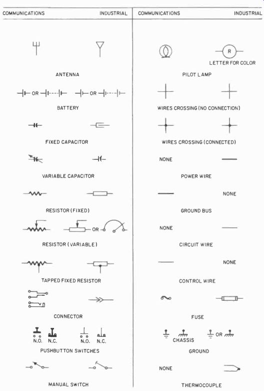
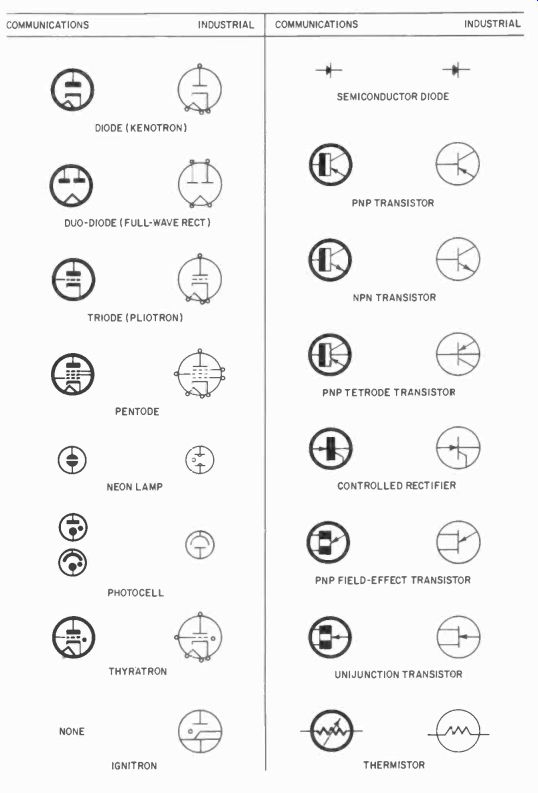
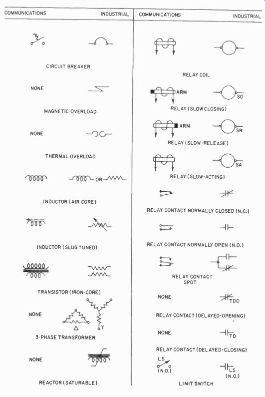

Fig. 201. Comparison chart of symbols.
Components in industrial applications are often heavier than those in communications, hut many of them are very similar. The great stress on reliability often makes it necessary to allow greater margins of safety, for example in transformers, which will be built larger and sturdier for industrial purposes. Unfavorable environ mental factors, such as extreme temperatures, steam, vapors of different kinds, corrosive fumes, dust; explosive gases, vibration and mechanical damage possibilities place particularly severe demands on the enclosures and wiring of industrial electronic devices.
Vacuum tubes used in industrial devices may be like, or very similar to those in communications gear, but more often specially-constructed ruggedized tubes are used. Their extra supports and special structures are more capable of withstanding extreme mechanical vibration. Often vacuum tubes in industry are very large, and some special kinds are used which are never found in communications. On the other hand, some of the communications special tubes, such as magnetrons and klystrons, have been pressed into industrial service when needed.
In this Section, we will emphasize the differences in each of the foregoing classes of equipment and devices, but we will report on some kinds of electronics which have no equivalent in communications. Needless to say, we will not be able to report on all practices and devices, systems and customs, equipment and circuits. A choice has been made which will cut across many of the existing subdivisions in industrial electronics, since it is our aim to give you the "feel" of industrial electronics, rather than to try making you into an expert.
Symbols, diagrams and drawing techniques
When you look at an industrial diagram for the first time, you may have difficulty reading it. The symbols you are accustomed to have been mixed up with a new bunch which are unfamiliar. This is partly the result of not too successful attempts by manufacturers to standardize diagrammatic symbols. Then, too, there has been the frequent necessity to have the diagrams fit in with power circuit diagrams, which use symbols much like those used in the industrial circuit diagrams.
Fig. 201 is a chart of symbols used in industrial practice and in communications. Note that the symbols for vacuum tubes are the same, but that resistors and capacitors are different. In industrial diagrams you may meet two parallel lines which look like a capacitor, but in fact are relay contacts. Or two parallel lines with a slant line through them, which looks as if someone started to draw a variable capacitor and forgot to draw the point on the arrow to indicate variability. This is a normally -closed relay con tact. In drawing transformers, we often omit the lines representing the cores. In industrial practice, this is time -saving and quite justifiable, since we seldom use high-frequency coils and there is not so much chance for confusion. Sometimes coils and transformer windings are shown as you have been used to seeing resistors, a 60° zig-zag line. Other symbols in the diagram will provide clues to what system is used, and generally the draftsman will at least be consistent in the type used.
The American Standards Association (ASA) has tried to standardize symbols, but great difficulties arise in getting such symbols universally accepted. Many engineers and draftsmen in industrial electronics jobs were originally communications engineers and carry with them old habits of presentation. Manufacturers had extensive files of diagrams and catalog engravings before standardization became an obvious necessity, and the cost of changing all existing drawings is usually prohibitive. Magazines such as RADIO-ELECTRONICS, which count among their readers many communications -oriented technicians and engineers, continue to use communications symbols for good reasons. But large manufacturers, such as G-E, Westinghouse and many others are equally justified in using the new symbols, since their electronics equipment most often is part of a system, including also a great deal of power and control which could not be drawn in communications symbols. In this volume we will go along with magazine practice and show most diagrams in symbols familiar to you.
It is always simply a matter of time before a practice becomes adopted, and eventually industrial electronics will play such an important role in our lives that there will be a tendency to unify the symbols, generally favoring the industrial ones. But this may be a long time away. Meantime you must get along with the mix ture and compromises now used.
Wiring and elementary diagrams
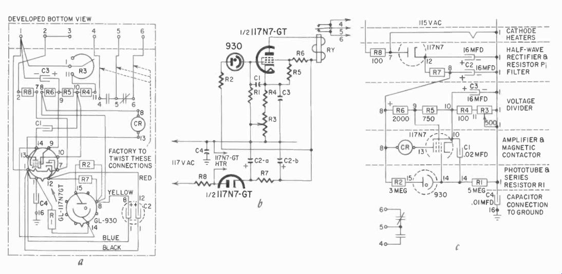
Fig. 202. Three methods of presenting the same electronic circuit.
Not only symbols are different. Drawing practices also vary. In industrial diagrams, we have long used wiring diagrams and what we call elementary diagrams, unlike the schematic diagrams used in communications. Fig. 202 illustrates the difference between the three kinds with a diagram of the G - E CR7505K108 photoelectric relay. Notice that in the schematic wiring diagram (6) such items as relay contacts are drawn adjacent to the coil, and that this is also true in ,he panel diagram, which tends to show the parts in a placement which is quite close to the actual physical relationship. But in the elementary diagram (c) we do not concern ourselves with this. There we are concerned primarily with showing the sequence of events. Thus if A must happen before B, we show A first, then B, even if they are part of the same piece of equipment. If we have a transformer and items fed by various secondaries, they are separated in the elementary diagram. We will cheerfully draw all the secondaries where they are needed, and thus scatter the parts of the transformer all over the diagram. This is graphically illustrated by separation of the relay contacts from their coil. Of course, parts thus separated must be adequately labeled for identification.
The practice of drawing elementary diagrams came in vogue with the introduction of complicated relay control diagrams, where the circuit often could not be understood without a clearly indicated sequence of events in the diagram. They served so well there that the practice was carried over into other kinds of circuits.
But this is not all. There may he other differences. One of them is illustrated in Fig. 203, in a very much simplified way. While in communications we draw all lines even if this means drawing many parallel lines, in industrial diagrams we may have so many parallel wires that the drafting becomes impractical. Then the draftsman will pull these wires together into one line and will designate the origin and destination with a number as shown.
This does not mean necessarily that these wires would be cabled together, although they often are. Generally it is simply a convenience adopted for simplification of the diagram, while in communications we avoid this for the very reason that the assumption might be that these wires are cabled.
We can go one step further and omit the lines altogether, simply designating the origin and destination of the wires. This is a long established practice in wiring diagrams such as are used in large powerhouse switchboards and control systems, and is being carried over into industrial electronics. For one accustomed to reading such power diagrams this presents no problem, but for a communications technician, who is accustomed to having every line drawn, they may need some study. Yet it seems a logical and commendable simplification which saves much drafting time and keeps diagrams quite uncluttered, a necessity when the systems get large and complicated.
Single-line diagrams
Long familiar to communications are the block diagrams, which have their equivalent in industrial diagrams when we draw single (one)-line diagrams. These are essentially similar to block diagrams, except that instead of empty "blocks" with designations written in, the single -line diagram often show the more graphic symbols common to the power business. Fig. 204 illustrates the difference. Single -line diagrams were introduced for the same reasons as block diagrams: simplification and a quick view of an entire system and its major components.
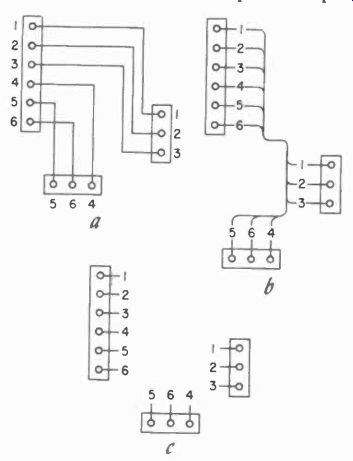
Fig. 203. Schematic in (a) indicates wire connections between terminals.
Connections in (b) and (c) could indicate individual wires or multiple
wire cables. Additional data on the print would clarify this.
Construction diagrams
A fifth kind you may encounter is the construction diagram.
This is very much like the "wiring" diagram, and sometimes serves the same purpose. The construction diagram illustrates components in their actual physical relationship, with quite a bit more accuracy than a wiring diagram, but with only the terminals shown. Thus, rather than vacuum tubes and transformers with their internal construction schematically presented, only circles or rectangles will be shown with the actual terminals and socket connections. Unless one is quite familiar with all the components involved, it is almost impossible to determine function from a construction diagram. The construction diagram will also indicate how wires are to be dressed, whether or not they are to be cabled, and how various parts must be fastened. Usually several construction drawings are needed for one chassis.
These are the most important differences in diagrams you may have to cope with. There are many hybrids --wiring and construction diagrams mixed, schematics and elementary diagrams mixed, wiring schematic diagrams combined and so on. Nor can you expect to find a pure application of symbols of one kind or another everywhere. But knowing about the possible differences is half the battle in coping with them.
Industrial circuits
In industrial electronics a preponderance of circuits designed for control are utilized while a limited number of circuits commonly used in communications will also appear in industrial applications mostly in the various instruments used. For example, counting circuits, not a part of communications per se, are very important in industry. You will find considerable data devoted to them in Sections 5 and 6.
Industrial controls of all kinds using photoelectric and timing circuits and certain kinds of phase -shift circuits are entirely strange to the communications field. A number of these can be found in Section 7.
Industrial power generators are very similar to simple communications transmitters, with the exception of the power sup plies. Section 3 deals with such generators in some detail. These generators must not radiate beyond their immediate working area, and thus differ also in that respect.
Completely strange to communications work are the static switching circuits discussed in Section 8, and the somewhat more familiar circuits in Section 9, which deal with transistors and other nonlinear elements. These are more closely related to computers, as are the other logic circuits discussed.
A new class of devices are the recorders of Section 10. The amplifiers in these are quite different again from those used in communications. Here you will encounter dc amplifiers, and amplifiers using ac instead of dc to supply power.
And finally, there are the multitudes of transducers, a few of which are discussed in Section 11, also foreign to communications.
We can sum up by saying that in industrial electronics we are primarily concerned with two functions, control and measurement. And the two are interrelated, for to control with any accuracy we must measure.
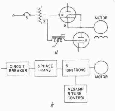
Fig. 204. Block diagram and single line diagram are different ways to
show the same circuit.
In industry, circuits should be kept as simple as possible, with as few components as we can manage. Each additional component is a balance proposition between increased accuracy or function complexity and reliability, since each component is a potential source of trouble. The use of ac as a source of plate power for direct use in amplifiers is based on the desire to eliminate the rectifier and filter system as potential trouble sources, not on cost. If we can do a job so much better with a dc supply that the additional components are warranted, we would certainly do so.
Sometimes the impression is given that industrial electronics is a crude kind of affair, dealing with large power or very approximate measurement and control. Nothing could be further from the truth. Some industrial controls work with high accuracy in measurement as well as control, and often under exceptionally difficult circumstances. It is one thing to measure a temperature rise of a few degrees at room temperature, but quite another to do the same thing at several thousand degrees. It is easy enough to weigh and balance a few pounds or ounces accurately, but much more difficult to do the same thing with the same degree of ac curacy when weighing 60 tons of material in a hopper all at once! Industrial electronics, in fact, is often more difficult and demanding than communications practices, and many special circuits have been developed to do the job adequately. This includes many jobs of control which for a long time were considered "impossible." Many times industrial electronic controls have come to the rescue where other controls would have been possible but extremely cumbersome. Thus the delicate remote "hands" of a servo system designed to handle radioactive materials safely and as delicately as with one's own fingertips, depend on electronic control circuitry. In machine control, electronics provides accuracy which could not even be read, let alone adjusted, by human beings.
Industrial components
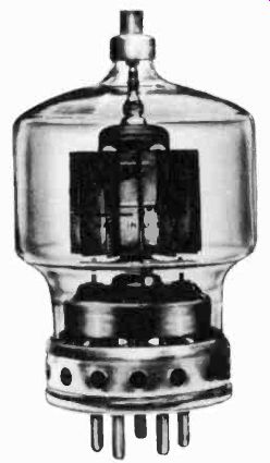
Fig. 205. Forced-air can be used to cool tubes. Holes around the bottom
prevent heat build-up in the base.
When we speak of components in electronics, we more or less naturally think of vacuum tubes first. Many of the vacuum tubes used in industrial electronics are identical to those used in communications; you will recognize many of the numbers, shapes, sizes and bases. But even then you may be dealing with special versions such as the so-called ruggedized types which have been specially built for military applications to withstand severe vibrations and environmental conditions. Industry has happily adopted the use of similar tubes in equipment subjected to similar environmental conditions, thus solving some of the reliability problems that plagued the application of electronics to industrial problems in the beginning.
Unless you are accustomed to dealing with transmitters as well as receivers, you may not be familiar with some of the larger versions of vacuum tubes often used. Fig. 205 shows one that might be used in dielectric generators of moderate size. A number of these tubes can be and often are used in parallel. The radial -beam tetrode is very familiar to amateurs and transmitter engineers.
This tube is capable of as much as 1,600 watts continuous plate output. A more modern type is the ceramic version of a power tube (Fig 206), also a tetrode, but cooled by air blown through the fins, and capable of a maximum of 3,600 watts of useful output.
Other tubes are capable of even greater power output and can handle as much as 10 kw. Beyond this size, we generally employ water-cooled tubes such as the one shown in Fig. 207 and its larger cousins.
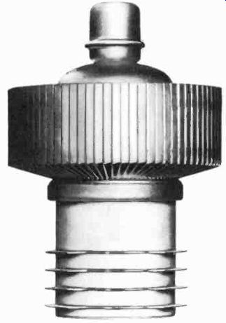
Fig. 206. Forced air conducts heal away from the radial heat dissipating
fins.


Water-cooled tubes pose special problems for service technicians.
Although these tubes can not long remain in operation without a proper supply of cooling water, cold water cannot be used directly. The temperature stresses in the metal and in the seals would be too great. The tubes are most often cooled by water held in a closed circulating system which allows the proper regulation of water temperature and the maintenance of the purity of the water. Contaminated or hard water might clog the cooling comparatively small one is water-cooled, since without proper cooling, de-ionization might be irregular.
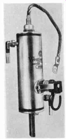
Fig. 209.Heavy ("neat applications call for the ignitron, the big
brother of the thyratron.
The next step up from ignitrons are the mercury-pool rectifiers, which function in a similar manner but are many times the size of ignitrons. Some mercury pool rectifiers have been made for currents of 20,000 amperes. Many of the larger ones are used by railways for supplying dc power to the system, and in the metal-processing industries for electrolytic deposition of copper and in the manufacture of sponge iron and aluminum. (A cross-section of a mercury-pool rectifier is shown in Fig. 210.) Magnetrons are shown in Fig. 211. Those illustrated are smaller than the magnetrons used in Radaranges. Other special tubes you may have to deal with include the vidicon and the photoemission image orthicon, both camera tubes. The circuit for the vidicon (Fig. 212-a) is discussed in Section 11. The orthicon is shown in Fig. 212-b.
Photocells are a regular part of industrial equipment, and may range from the sensitive photomultiplier used in instrument applications to the simple solar cells applicable in control.
Another special kind is the counter tube, particularly the decade type. Two representative units are discussed in Section 5, the gas type Dekatron and the magnetron beam -switching tube.
A special variety of indicator tube, the Nixie, is in effect a neon tube with one anode and a number of cathodes in the shape of numerals or letters. It is only used for numerical readout of counters and computers, and does no counting.
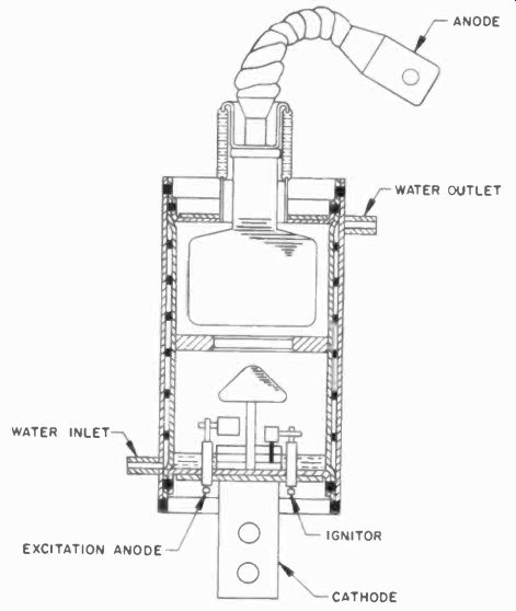
Fig. 210. Drawing of a typical mercury-pool rectifier shows location of
connections. Tube is enclosed by a water jacket.
Geiger-Muller tubes (Geiger or G -M tubes for short) are specially designed for measuring radiation. High -vacuum types made of extremely thin glass or metal, or supplied with an extremely thin mica window, they contain a small amount of gas. They operate on what is called the "gas-multiplication" principle. A particle entering the tube at a relatively high velocity will, in its path through the tube, create a number of ions which are then attracted to the anode, usually a thin wire with a very high voltage (up to 1500 V) on it. The ions striking the anode create a quite measurable pulse. Some Geiger tubes are shown in Fig. 213.
There are also other ways of measuring radiation, such as the photomultiplier, which is used in conjunction with a crystal possessing the peculiar property of creating light when particles strike it. The particles used are generally sodium iodide crystals, and they are mounted directly against the tube face, so that any light within the crystal is detected by the photomultiplier. This is known as a scintillation counter, and it is very sensitive.
Industry also uses special tubes such as cathode-ray type storage tubes, which can hold an image for an indefinite or sometimes for a limited time. In these the phosphor layer is so designed that a charge is maintained which keeps the image visible for the desired time. There are other tubes for special applications which are not strictly industrial which you may, nevertheless, encounter, but, as a rule, the tubes discussed are representative of the field.
Semiconductors
Semiconductor devices have long been used by industry. The first one was the selenium rectifier, which was made in very large ratings for industrial work. Germanium, and particularly silicon, are replacing selenium rectifiers. A silicon rectifier, which can be controlled like a thyratron, can be used in a large number of applications. For details, see Section 9.
Transistors are already in use in industry to some extent, but not as much as they will be when they are manufactured for larger currents. Unijunction transistors, trigistors and several other semiconductor devices applicable to industrial electronics are all discussed in Section 9.
Inductors
Transformers in industry are indistinguishable from those used in high-quality communications equipment, and no purpose would be served by describing them in detail. Other devices physically comparable to transformers are the saturable reactors and magnetic amplifiers. Their operation and application is covered in Sections 8 and 9. Some, especially those for control -system applications, are molded in plastic. Their operation in control systems is explained in detail in Section 8.
Resistors and capacitors
Resistors and capacitors are generally familiar types, although you are likely to find more of the canned, oil type capacitors, since they are better suited for operation in the difficult environmental conditions frequently encountered in industry. It might be advisable to point out here that the capacitor insulators should be cleaned periodically during routine maintenance checks, while observing the usual precautions for discharging them first.
Large molded -base sockets with screw type terminals, and heavy duty supports, terminal hoards and tie points are used in industry because there is virtually never any need for miniaturization. In fact the sacrifices made in reliability, repairability, economy and freedom of access to gain compactness are often a detriment in industry. Industrial equipment is built in large enclosures, with plenty of space for ventilation and easy access to components and terminals. In other words, there is an altogether different philosophy in its design, with emphasis on ruggedness rather than compactness, reliability rather than light weight, and durability rather than economy.
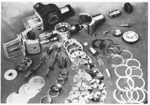
Fig. 211. Magnetron construction is much more complicated than ordinary
vacuum-tubes.
Industrial enclosures
Communications equipment is often installed on open relay racks, particularly when space can he assigned for them separate from the rest of the building. Frequently, a basement is used be cause cables often come in underground, and the basement is the nearest place.
In industry, equipment is seldom concentrated in a single location, and most frequently is in close proximity to each ma chine that it controls. Open relay -rack mountings are, therefore, obviously both uneconomical and unsuitable. It is preferable to have separate cabinets, wall -hung or suspended from the machines or self-supporting and set on the floor near the machines.
If the atmosphere in the plant carries any quantity of dust, the box must be dust -tight with a gasket in its door. Ventilation is then supplied by blower through air filters which will also require periodic maintenance. Where there is a possibility of water or moisture splashing on the equipment, the gasket must be water proof and the air filters must also be designed to keep moisture out.
In industry you will also see enclosures which are explosion -proof. Contrary to popular belief, an explosion-proof enclosure is not designed to exclude an explosion so much as to contain it.
The enclosure will be compartmented, with seals between compartments, so that an explosive gas or mixture entering one compartment cannot get to another. The case is sufficiently strong so that, if the gas should explode within a compartment, it will be contained and not start an explosion in adjacent compartments of the general environment.
Industrial enclosures are specified and standardized by the National Electrical Manufacturers Association (NEMA). For industrial controls their standard is NEMA ICI 1949 which describes and classifies enclosures according to their ability to withstand environmental conditions. Type 1 is a general-purpose enclosure.
Type 2 is similar but with a drip shield to keep dripping moisture out. Type 3 is weather -resistant and can be left out in rain or blizzards. Type 4 is watertight --in other words, not submersible, but capable of withstanding a direct splash from a hose. Type 5 is dust -tight; Type 6 submersible; and Type 7 is explosion proof for hazardous locations where explosive gas and vapors are present. There are several classes of Type 7 enclosures. Types 8 and 9 are also for hazardous locations; Type 10 is approved for mines;
Type 11 is acid- and fume-resistant, and Type 12 a general industrial applications enclosure, normally non-ventilated to keep out flying material such as metal chips, etc. NEMA standards specify thickness of metal for all of these enclosures, the method in which the doors are fastened, maximum sizes and volume, temperature rise allowed, etc.
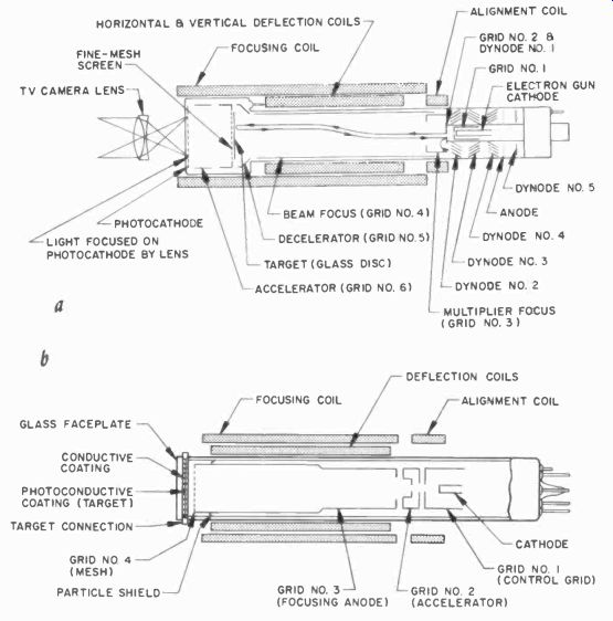
Fig. 212. The vidicon (a) and orthicon (b) are used with lens systems
as signal pick-up tubes in industrial and broadcast TV.
Insurance underwriters also have standards which must be met, and it has long been a practice that union electricians will not in stall any equipment that is not underwriters approved. The reasons for this are not primarily a result of "union politics" but are generally a matter of responsibility. If a piece of equipment is installed and blows up, someone is likely to try to blame the electrician for the failure. The underwriters' label guarantees that the equipment meets minimum safety standards, and gives the installing electrician some measure of assurance that the equipment is not going to kill someone on the second day it is in use.
Rules, regulations and codes
Any equipment installed in a plant where contact by employees is possible will be subject to local, state and possibly Federal safety regulations. Nationally, installations are designed to comply with the National Board of Fire Underwriters Safety Code, called National Code for short. This is a code set up for safety of personnel by fire and liability insurance companies. They will not insure equipment or installations which do not meet inspection. The code has been generally adopted by city inspection and fire departments as well, and all of these must be given access to the plant for inspection. Utility companies will not supply power to uninspected equipment. Even major changes of any kind to the equipment require a permit from these departments in many cases. It is always a good idea to check with them if changes are contemplated.
Some local or state authorities have stringent rules for installations, particularly when large numbers of people work in the same room with the equipment, and just complying with the National Code may not be adequate. If equipment is installed on Government property, Federal regulations must be met. Generally, safety requires that any power wiring carrying over 50 volts must be concealed or completely enclosed so that no one can touch a live wire, terminal or contact. Certain requirements are set for the wire and cable used so that overloads will not heat the cable excessively. Special requirements must be met for dangerous high -voltage equipment (above 250 volts). Much of the power equipment operates on a 440-volt (and higher) 3-phase supply.
Equipment containing oil or other inflammable substances must be shielded or separately enclosed, unless the filling can be replaced with a noninflammable substance such as is used in many power transformers. Temperature conditions must be met to prevent the equipment itself from heating to dangerous temperatures, causing breakdown and possible fire. Specifications are set for insulation requirements for different temperature ranges and mechanical-fatigue conditions.
Industrial power sources
When installing, repairing or preparing to service industrial equipment, keep in mind that 110 -volt power is the exception rather than the rule in industrial installations. More likely you will encounter 208, 230, 360 or 440 volts. Here's why: Most industrial power sources are 3 -phase. The 3 phases can be separated, but a single phase from a 3 -phase, 220 -volt supply would be 220/0:= 125 volts, not 110. A 120 -volt, single-phase line is likely to come from a 208-volt, 3 -phase supply. On the other hand, if your single-phase supply is 208 volts the main supply would be 360 volts, 3 -phase.
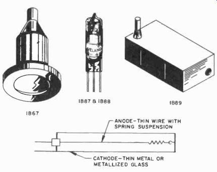
Fig. 213. Geiger -Muller tubes have a variety of shapes. The basic internal
construction is shown. (Victoreen Instrument Co.)
Ground
Some of the supplies are grounded, and some are not. If you have to work on the equipment, it is advisable to determine beforehand the voltages to ground. A 3 -phase system may be grounded but not symmetrically. For example, in what is known as a 4 -wire delta system, 110 -volt power is obtained from a tap on one of the 3 -phase windings of the power transformer. This is not an uncommon system where the power load is much greater than the lighting load.
Fig. 214 shows the different systems in use, and typical power symbols. Often, for safety or load reasons, separate transformers are used for the lighting and instrument loads, and single-phase or 3 -phase, 4 -wire transformers then step down the power voltage (usually 480 volts, 3 -phase) to 120/208 or 110/220 for the lower -voltage circuits.
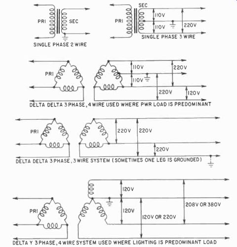
Fig. 214. Single- and three-phase industrial power transformer and line
connections, with related voltages indicated.
Special attention must be given to circuit protection at all voltages. The National Code sets up branch -circuit specifications, and electronic equipment must conform to these. Failure of a circuit breaker to open a branch supply in case of a short circuit could result in the shutting down of an entire section of the plant, or even the whole plant itself. Failure of a circuit breaker can be caused by inadequate interrupting capacity, which should be based not on the normal current requirements of the equipment but rather on what the system would apply to the circuit breakers if a dead short occurred just inside the equipment. For this reason the circuit breaker on some kinds of equipment may appear to be too large for the load. In such cases the equipment may be integrated into a system which could blow it sky-high if the circuit breaker failed to interrupt a short-circuit surge of power. This is not just a figure of speech since equipment has been blown clear through plant roofs because of the devastating electrical forces created by short circuits.
Similarly, any electrical bus system carrying substantial power should be adequately supported. With heavy currents in two copper buses going in opposite directions, the buses will try to separate; with currents going in the same direction, the magnetic forces involved will tend to pull them together. Fantastic short circuit forces may result in the system.
Fuses and circuit breakers
For many years now fuses have been supplanted by circuit breakers in most applications, but in some modern industrial equipment more up-to-date fuses may be used in place of circuit-breakers. Modern fuse design takes into consideration the interrupting ratings, and such fuses are quite different from those of 20 years ago. The power end of industrial equipment must be properly integrated into the plant system in accordance with code specifications, and should not be a haphazard, unplanned network with minimal branch -supply protection (Fig. 215).
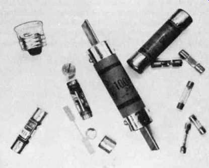
Fig. 215. Fuses range in size from small instrument types to the giants
having ratings of 100 amperes. Some of the larger ones have a replaceable
element.
Summary
From the foregoing, it is readily apparent that there are substantial differences between communications and industrial electronics equipment. Industrial equipment often must stand up under more severe environmental conditions, usually operates under heavier duty cycles, and furthermore, is likely to receive less attention from maintenance personnel. Some of the differences in diagrams, circuits, components and methods, as well as installations, have been discussed.
In regard to specific location of electronic control equipment, it will often be installed in an inconvenient place, from the technician's viewpoint, since in many cases control equipment was often added long after the plant had been in operation, and after most of the available space had been assigned to production machinery and materials-handling equipment.
Finally, it is well to remember that in industrial electronics the reader is not facing something out-of -this world, something strange and unusual in terms of electronics, despite certain obvious peculiarities of this equipment. Now let us look at specific equipment--their uses, circuits and operation, in the Sections which follow.