AMAZON multi-meters discounts AMAZON oscilloscope discounts
Of all the control functions in industry, counting is by far the most prevalent and, in a sense, the most important. Counting is applied wherever there is a repetitive process, whether it he manufacturing or only processing and packing. Thus jelly beans are counted into the bags in which they are sold, and so are steel balls for ball bearings. This counting may be a very crude approximation; for example, when the objects are simply weighed and their weight made a certain number of times the weight of a single jelly bean or other object. But more often than not, the counting is a precise procedure. Gallons of oil leaving a refinery are counted, nuts and bolts produced by automatic screw machines are counted and, very important, time is counted. How these counting procedures are used in industrial applications will be the substance of the next Section. In this Section we will review the methods and instruments used in counting.
Principles of counting
Since the reader has been counting since he was a child, it may seem superfluous to tell him the principles of counting. This may be true enough when we talk about counting in the system which is most familiar; counting by tens or in the decimal system. Many types of counters can do this, particularly the mechanical counters which operate by a series of toothed wheels with numbers on them. Although these counters are very widely used in industry, they have very serious limitations. The worst one is that they can be used for counting only up to a certain speed, which is the limit of their mechanical endurance. Beyond this, the mechanical counter would simply refuse to count accurately or, would literally fly apart. Electronic means of counting must then take over, and there are a number of decimal electronic counters which we will discuss presently. But first we must talk about another method of counting. This is counting in the binary system, or counting by powers of 2. The reason for its popularity is that it effects important savings in electronic circuitry, as you will see.
First, let us take a brief look at what binary counting is. Binary counting is quite old. It was invented long ago by a German philosopher named Leibnitz, who hoped to use it to convert the Emperor of China to Christianity. He did not succeed, and the story does not tell why. Binary counting is extremely important in the industrial picture because of the rapidly expanding applications of digital computers which utilize the binary principle.
Binary math is figured on the base 2 rather than 10. In the decimal system, we have units, hundreds, thousands, etc. all multiples by 10. In the decimal system we can write any number as a power of 10. For example, 100 = 10^2 and 1,000 = 10^3 and so on. Or take a complicated number like 13,271: 13,271 = 1 X 10^4 + 3 x 10^3 + 2 x 10^2 + 7 x 10' -1- 1 X 10°. Let's check: 10,000 + 3,000 + 200 + 70 + 1, sure enough adds up to 13,271.
We have used only one little trick here: 10° = 1. Now this is also obvious, for we know that And we can write 100 = 1 and thus L02 = 1.
100 102 1 102 as 10^-2. Then 100/100 = 1 = 10(2-2) = 10°.
And just one more basic idea, since we will be using it again and again: why is 10(2 - 2) the same as 100/100? Let us start by taking another set: 1,000/100 = 10 or 10^3/10^2=
10' and we see that the exponentials in division are subtracted and in multiplication they are added.
The powers of 10 are familiar from daily use: as 1, 10, 100, 1,000, 10,000, 100,000, etc. But the powers of 2 are not so familiar when the figures get large (Table 5-1). Notice how fast we get up into large figures.
--------------
TABLE 5-1
0 1
1 2
2 4
3 8
4 16
5 32
6 64
7 128
8 256
9 512
10 1,024
11 2,048
12 4,096
13 8,192
14 16,384
15 32,768
16 65,536
17 131,072
18 262,144
19 524,288
20 1,048,576
------------
.....in other words, 2^3= 8 and 2^4 -= 16 etc.
Of course you could easily have constructed this table yourself, since each figure is just twice the preceding one. Now we can express the number used in the preceding example in the binary system. Thus: 13,271 = 2^3+ 212 + (no 211) + (no 210) + 2° + 28 + 27 + 28 + (no 25) + 24 + (no 28) + 22 + 21 + 2°. We simply take the largest power of 2 that "goes into" the number, mark it down and subtract it. Then we look at the next power of 2 and, if we cannot subtract, we write (no) and go on to the next power we can subtract, mark it down and so on. Each time we subtract we mark it down, and each time we cannot sub tract we mark it down as (no . . .).
For 13,271 we have in effect said: yes, yes, no, no, yes, no, yes, no, yes, yes, no, no, yes, yes. Now if we write, for simplification, for the times we said yes 1 and for the times we said no a 0, then we have a very simple notation indeed: 13,271 = 11001111010111. And this is a handy notation, and we could say, equally well that 1 stands for a closed switch or relay contact and 0 for an open one.
In spite of the simplicity and apparent monotony of this nota t ion, we can simply and very quickly carry out arithmetical computations with this method. And, in effect, this is all that is done by the most complex computer-simple arithmetic operations.
In effect, all a computer does is add or subtract. As you may remember from your grade school days, long division is simply a matter of subtracting, and multiplication primarily a matter of addition. Leibnitz, the philosopher, wrote down all the necessary
mathematical operations in a simple table, and we will show this table, but first let's see how and why the operations go the way they do, and let us carry out some of them. Suppose we have a 1, which means that we do have that power of 2, say 22. If we put under it another number which also had (1) it will also be 22 = 4.
Now we add 4 + 4 = 8.
But 22 + 22 = 23, which is not 24 but 28, the next higher power of 2, and nothing else.
Thus if we have a 1 and add a 1, we get the next COLUMN notation of 1 0 (it is pronounced one-oh) because we have now the next higher power of 2 and we have used all the powers of 2 we started with. Leibnitz put this in his table as: 1 + 1 = 10, which does not seem to make sense, until you realize that we just shift our "yes" notation one column to the left.
Try it with another power: 23 = 8, so 23 + 23 = 8 + 8 = 16 = 24 See? It works with any of them.
Similarly, when we subtract, we shift to the right, thus: 10 - 1 = 1 or rather, as we should write, 01. If we have a "yes" in the column of 24, this as we have seen is 2 times 23. So if we take 23 from that column when there isn't any (we had 1 0), we must borrow from the 24 column. This means we have nothing left there (0), and we are left with 1 times 23,thus 10 - 1 = 01.
You can work out the same thing for 11 - 1 (or as we could write 11 - 01), and this equals 10. And 10 + 01 = 11. Thus we get painlessly through most of Leibnitz' table of operations:
0 + 0 = 0 0 X 0 = 0 1 + 0 = 1 OX 1=0 1 + 1 = 10 1 X 1 = 1
This, it says in fine print, is all you need to know to work in binary math!
Let's see if it is true.
For example, the simple addition 35 + 11 = 46 35 = + 0 + 0 + 0 + + 2° or 100011 11 = + 0 + + 2° +1011 101110
Now read with us from right to left: 1 + 1 is 10, so the first digit from the right is 0 and we carry a 1. Now again 1 + 1 = 10, so our second digit would be also an 0, except that we carried a 1 so it becomes 1, for 0 + 1 = 1. Then: 0 + 1 (which we carried this time) = 1 and our third digit from the right is again a 1. Next 1 + 0 = 1 and our fourth digit from the right is also a 1. Then
0 + 0 (which we did not write!) = 0 and 1 + 0 (which we did not write) = I so our number is one oh one one one oh, or 101110.
Subtraction goes the same way when we "talk it out":
30 which we write 11110
-11 - 1011
19 10011
Let's see if it is right. 19 = 24 + 0 + 0 +2' + 20 = 16 + 2 +1 Now, using Leibnitz' table, let's try multiplication:
Multiply 11 X 3 or, as we "skilled mathematicians" can now write it:
1011
X11
1011 (remember Leibnitz' table)
1011 100001 Add! or 25+ 0+0+ 0+0 + 2°= 32 + 1=33 And so on to division (remember that 10 - 01 = 01):
Take: 55 11 = 5
1011 I 110111 (2' + + 0 + 22 + 2' + 2°)
1011
0010
0101
0000
101
1011
1011
0000 (no remainder!)
and the answer 101 = 2' + 0 2° = 4 + 1 = 5
You have now gone through the basic arithmetic operations in binary math. Not difficult, is it? Of course, you can develop skill only with practice, but fortunately you won't need it. That's what computers are for. You can also see why we can use flip-flops, for they conduct either on one side or the other: yes or no. 1 or 0. Or, as Berkeley showed so nicely in his simple computer series in late 1950 and early 1951', we can do it with relays. Call a relay contact closed 1 and a contact open 0, or a coil energized 1 and a coil de -energized 0. There you have it.
[1. "World's Smallest Electronic Brain" series, Edmund C. Berkeley and Robert A Jensen, RADIO-Electronics Magazine, October 1950 to October 1951.]
Economy? Well, to show a number like 13,271 in lamps on a binary computer panel we need 14 lamps, thus 11001111010111.
To show the same thing in the decimal system, we need this:
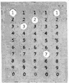
A total of 50 lamps, almost four times as many!!
This is only an illustration. There is much more involved besides the so-called readout lamps, and the economy shown there is duplicated in other circuitry. The flip-flop is an excellent circuit for distinguishing between the 1 and 0 conditions. In it a tube will alternately conduct and not conduct; thus, the switching operation or "counting" can take place very rapidly, as fast as 10,000,000 times a second, and the parts are not subject to mechanical wear. For this reason the majority of industrial electronic counters up to now have been based on the flip-flop circuit. Al though beam switching tubes are rapidly taking their place, flip flop counters still predominate and you should understand their operation.
Fig. 501 shows the basic flip-flop circuit or bi-stable multivibrator. This is a well known circuit in the electronics field, and any good reference book can give a detailed explanation of its functioning. Briefly, it is this: Upon a positive signal on its grid or a negative signal on its plate, a nonconducting tube will suddenly be made conducting and, through the feedback coupling capacitor, the opposite member of the team is switched from conducting to nonconducting. Therefore, the flip-flop changes state for each pulse, and returns to its original state every second pulse.
Now then, if we were to cascade flip-flops-put several of them one after the other, with the pulses for the following ones to be produced by the preceding ones-you can see that the first flip-flop or binary as it is called would return to its original state every 2 pulses, the next one every 4 pulses, then 16, 32 and so on. This is a true binary counter and in this form is used in counting radio active particles. The answer need not necessarily come out in the decimal system, since we are usually satisfied if we can simply count the particles very rapidly and then, by a simple arithmetical operation-division by 8, 16, 32, 64, etc.-arrive at the true number of particles which have passed through our counter.
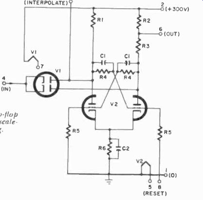
Fig. 501. Basic flip-flop circuit is used for scale-of-two counting.
Fig. 502 shows such a straight binary counter, and you will notice that the coupling between the binaries is made through diodes which apply negative pulses simultaneously to the two plates of the next binary. Only the binary tube which is nonconducting is affected by these pulses, making the binary change state. Sometimes it is sufficient simply to differentiate the signal supplied by the drop in voltage across a plate resistor by means of a very small capacitor of the tube just starting to conduct, and we then do not need the coupling diodes. In fact, most industrial counters use such a differentiation network and no coupling diodes.
Because the decimal system is commonly understood and used, binary counting can be inconvenient and clumsy. How can we use the same flip-flops for counting in tens? Many ways have been devised, but we will show several here which have become quite popular.
Nothing that happens in the Hip -flops can be observed from the outside of the tubes, unless we provide some sort of indicator.
In Fig. 502, small neon lamps indicate whether a tube in the binary is conducting or nonconducting. This is useful information, but it still allows us to count only in 2's, 4's, 8's, etc. But let us construct a table which shows the state of the binaries after a certain number of pulses (Table 5-2).
In this table 1 means conducting, 0 means cut off. The left figure is the left triode and the right figure is right triode in the binary.
TABLE 5-2
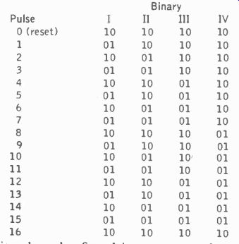
Notice that it takes the first binary two pulses to return to its original state, and the last binary 16 (at the input). If you observe this table carefully, you will discover that, although these "states" may have the same situation on one, two and sometimes even three binaries, with the state of only three binaries we can show the entire state of the counter-if we include the binary which is different for that count. For example, count 4 and count 12 look very similar, but notice that the fourth binary in count 12 has a different state. Thus if we make sure that in count 12 we can always identify the state of binary IV, we can always distinguish it from count 4. Now if we were limited in our binaries, we could even distinguish the states of all of them, and thus the count up to 16, by remembering all the lamp combinations. But that is too much trouble so we design a circuit in which four binaries indicate each count, using, say, 10 lamps. This is shown in Fig. 503.
This happens to be the circuit of a decade counter, and we will go into its other features. Notice first of all that there are 10 lamps, and that each of these lamps is controlled through voltage dividers by four binaries. Thus the state of the first, second and fourth binaries control the condition of lamp 0, and also lamp 1; the first, second and third control the condition of lamps 2 and 3, and so on.
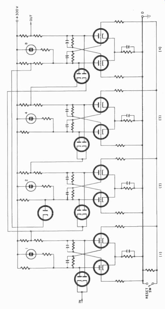
Fig. 502. Four scale -of -two flip-flops will count to sixteen.
This decade shows how to use four flip-flops to count to only 10, not to 16. How is this done? Notice that from the third to the second binary there is a feedback loop. And from the fourth to the third there is another feedback loop. These loops, since they are connected to the grids of the tubes to which the feedback signal is applied, will carry a positive triggering signal when the Hip -flop tube from which they originate becomes nonconducting. Let us construct another simple table to show what happens through these feedback signals. For convenience, we will repeat Table 5-2 in Table 5-3, to show the difference.
TABLE 5-3
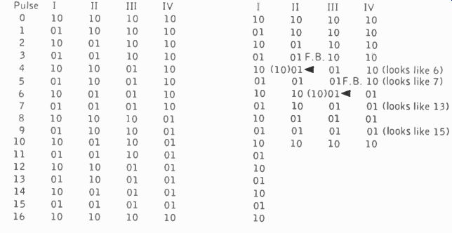
Fig. 503. In this counter decade each neon indicator lamp is controlled by the slate of four binaries.
Look at the right half of Table 5-3 and see what happens. On count 4, binary II tries to change, but binary III also changes and, through the feedback loop, prevents II from changing state. The effect is that, when this pulse has occurred, the state of the flip flops looks as if we had received six pulses instead of four. To our eyes it does not really matter what happened inside the tube; all we can see are the neon indicators which tell where we are in counting. And if we can fool the decade and make it look as if it had had 6 pulses, but we call this 4, then we need add only 6 more to get 10.
Now go two more steps. The same situation occurs when binary IV is finally tripped after what seems to it to be 8 pulses (but actually is only 6) and its feedback loop prevents III from changing state. Here we have a situation in which we have actually received only 6 pulses, but it looks as if we might have received 12 instead.
Add 4 pulses, and we will have the same indicator lamp situation as if we had had 16 pulses, but we have only had 10, and so this circuit counts every 10 pulses, a decade.
Compare all the lamp combinations. Actual count 7 in the decade looks the same as actual count 13 in the binary type counter. Since we control our indicators with four binaries, and we can write on the face of the neon lamps any number we please, when we number them from 0 to 9, and circuit them as shown in Fig. 503, we have a decade, counting to 10, and for all the world indicating only 10 distinct states.
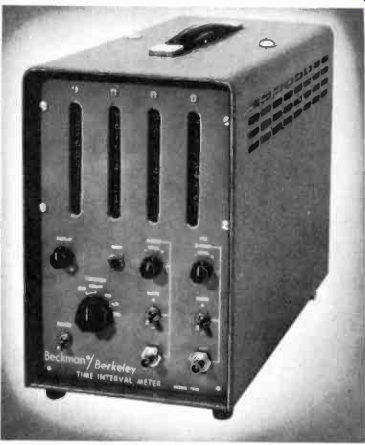
Fig. 504. One form of counter is called a time interval meter. (Beckman
Div. Berkley Inst.)
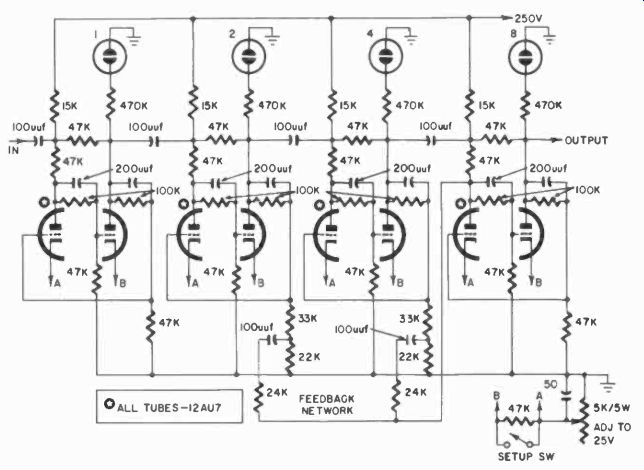
Fig. 505. A scale of 16 can be made to indicate tens by using feedback.
If we use several of these decades, one for the units, one far the hundreds, one for the thousands, and so on, we have a complete decimal counter. One form of such a counter is shown in Fig. 504.(Fig. 503 has another circuit at the bottom with two tubes and a switch, which we shall discuss later.) Fig. 505 shows another way to count by tens in flip-flops. Here, there is only one feedback loop, from binary IV to binary II.
What happens is that the counter first accepts 16 pulses and goes through 16 changes of state. But on the 16th pulse, the feedback loop resets binary II, and, as a result, the state of the flip-flops on count 16 is exactly the same as on count 6. Thus the decade is accomplished by similar changes of state and, when the next pulses arrive, pulse 17 looks like 11, etc. This has one disadvantage: unless the counter is reset properly to begin with we could lose the first six counts. However, a signal from a reset button (not shown) will do the same as the feedback from binary IV, and thus we can always start with what is actually 0, but looks in binary terms like 6, and thus count to 10 each time.
There are many other ways of doing the same thing, even without feedback loops, but the two methods discussed are the simplest and therefore the most popular. Your understanding of them will enable you to cope with any others.
We are accustomed to using vacuum tubes in counters, but they are not the only kind of device used. Fig. 506 shows a similar decade using transistors, and Fig. 507 a specially developed p n p n switching device which can obviously simplify such switching circuits. This is undoubtedly not the limit, and by the time this volume comes off the press, you can expect that new ways of making decades will have been invented. But, in essence, they will still be flip-flops, no matter how we simplify the components and circuits, and the principles of feedback for apparent counts, as we have shown them will still have to be applied.
Notice that in Fig. 506 a special bias circuit had to be used to develop sufficient voltage to make the neon indicators glow.
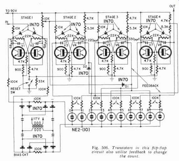
Fig. 506. Transistors in this flip-flop circuit also utilize feedback
to change the count.
With later model indicators this was simplified. For example, the Amperex 6977, an indicator tube specially developed for transistor circuits, is a subminiature triode with a specially-coated fluorescent anode which glows blue-green when a positive signal is applied to the grid, as in the "magic -eye" tube.
Some transistor counters use special low -drain filament type lamps for indicators. In principle, all these work the same, but the neon tubes (and the 6977) have the advantage that they pre sent virtually no drain to the transistor circuits.
Now for the extra circuits shown in Fig. 503. Here at the bottom, there are two twin triodes, so-called coincidence tubes. These tubes are simply biased in such a way, with all four plates tied together, that no signal is produced on the plates unless three of the four tubes simultaneously have a signal on the grid. Hence the name coincidence tubes. Which three will have the signal is determined by the setting of the switches. As with the indicator lamps, here, too, the binaries can determine any "state" of the counter. Thus we can produce with the two coincidence tubes a signal at any desired count of this decade. If we have such coincidence circuits on other decades also and require that all the signals from several decade coincidence circuits must again come at the same time (in another set of coincidence tubes), we can see that the switches can be used to set up any count number we wish. This signal produced through all these coincidence circuits can then be used to trip some device on a machine, say a packing machine, which will momentarily stop the machine. It can also reset the counter itself, and then start it over again.
Here we have what is called a predetermined or preset counter, a very useful instrument. For example, we can decide that we want exactly 317 jelly beans in a bag. We will set this counter for 317, and at that count the counter will give a signal, cutting off the supply of beans, sealing the bag, placing a new bag under the spout and start to fill the next one. Of course, all this will take additional controls, but the counter gives the start (or stop, if you will) signal for such a sequence.
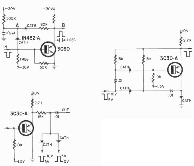
Fig. 507. One-shot multivibrator (upper left) provides delay between input
and output. Basic memory circuit (right) gives either positive or negative
output pulses. Flip-flop in binary stage (lower left) is also simplified
by PNPN transistor.
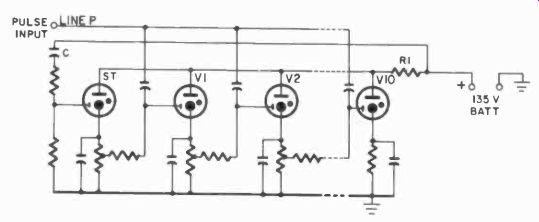
Fig. 508. Three-electrode type cold–cathode tubes can be used for slow
speed counting.
Other accessories to the electronic decade type of counters will be discussed in the next Section under applications. The electronic counter can be a very versatile instrument.
Shift-register counters and beam switching
So far we have discussed binary counters which can count by tens. Actually these are sly designs which count by two's and are only made to look as if they count by tens. However, that is all right so long as the end count comes out correctly. But there are also ways to count directly in groups of ten, without going through the process of feeding back flip-flops. Some of these ways are quite old, and some quite slow. First, we can of course do this sort of thing with relays, in a chain of ten, provided we make sure that when we pulse such a circuit, the second pulse turns on No. 2 relay, turns off No. 1, etc., and we count up the scale this way.
This kind of a circuit is interesting, and is used in telephone work; we will discuss it briefly under relays in another Section.
The simplest method is shown in Fig. 508. This is a chain of cold -cathode tubes on which the bias is so arranged that the tubes are almost ready to fire. To obtain bias for tube V1, a starting tube ST is included. When a positive pulse arrives on line P, tube V1 will fire but, since none of the other tubes is conducting, no other tube has sufficient bias to be almost conducting while tube V1 (with ST conducting) has the little extra bias needed. When the second pulse arrives, V2 is almost ready to conduct because of the voltage generated in its cathode circuit by the conducting V1, applied to the "starting" electrode of V2, and V2 will fire. But since all the tubes have a common plate resistor R1, when V2 fires, the voltage drop will be too great to maintain two of the tubes in fired condition. Storage in the capacitor in the cathode circuit of V1 holds this cathode momentarily at a high positive voltage and, when the anode voltage drops, this tube will be extinguished while V2 will remain fired. And so on up the line, until the last of 10 tubes has fired, when a reset pulse is required to fire ST again.
This simple kind of circuit is called a shift register. It is a limited circuit. The values of the cathode capacitors are critical and so is the shape and size of the pulse. Besides, these tubes take a certain amount of time to de-ionize (one reason for the critical cathode capacitor) and the speed of the circuit is quite limited.
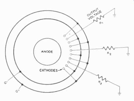
Fig. 509. Schematic of the Dekatron tube made for counting.
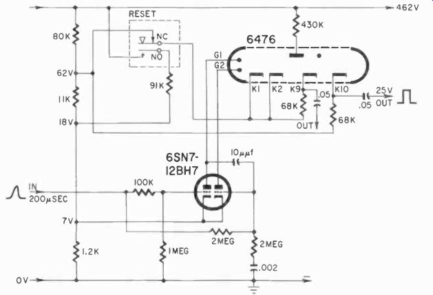
Fig. 510. Driver circuit for Dekatron is simpler than flip-flop decade
circuitry.
A more sophisticated version of such a shift register is embodied in a single tube, also a gas tube and known as a Dekatron. The 6476, shown in Fig. 509, has an anode, 10 cathodes and 2 sets of "ring cathodes" which are auxiliary aids for shifting.
Here is how this tube works: two pulses, (or actually a double pulse) is required for each "step." The auxiliary cathode rings are called G' and G". One cathode in the tube will always be glowing, and the gas in the tube partially ionized. Because the ionization is most dense near the glowing cathode, the striking voltage to the two cathodes adjacent to the glowing one will be lowest. The cathode voltage on the glowing one will, of course, be lower, due to the drop across resistor K. If the glowing cathode is K1, and we make ring G" strongly positive, then a pulse arriving on G' will tend to shift the glow from K1 and onto G'. But G' is not maintained at the proper voltage for striking, and thus the glow will shift to the nearest possible point, which would be K2 (G" still being positive). If we produce a pulse almost simultaneously on both G' and G", this action will automatically take place.
Fig. 510 shows a 6476 Dekatron with its driving circuit, a cathode -coupled multivibrator. Here, momentarily, the auxiliary cathode marked G1 will be lowered on arrival of an input pulse, and the cathode marked K1 immediately raised, as a result of the multivibrator change of state. This provides the necessary double pulse, one negative and one positive, to shift the glow, and the tube in effect counts the pulses. The reset circuit shown in Fig. 510 momentarily lowers the No. 1 cathode so much, with respect to the others, that the glow will jump to this cathode. This can, of course, be done electronically with a large negative pulse.
Several Dekatrons like this one can make a decimal counter but, because of de-ionization time required, the speed of such a counter is limited. The very best that has been achieved with this type of tube is 100 khz, but most other tubes operate nearer to a 20-khz maximum. There are ways to get around this limitation to some extent, as we shall see in the next Section.
A later development in switching tubes, one which is much faster and actually no more complicated in circuitry, is the so - called magnetron beam-switching tube. It is, in effect, a slightly large miniature tube with many, many pins, and a ring magnet surrounding the glass envelope. Inside the tube (Fig. 511), a central cathode is surrounded by 10 sets of elements, each set consisting of a spade, a target and a grid rod. Grids are tied together in two groups, but spades and targets are all brought out individually.
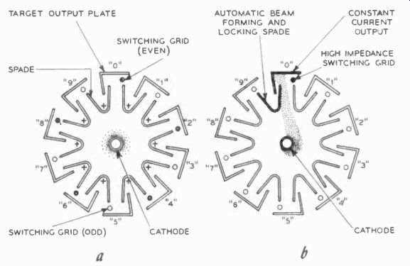
Fig. 511. During the CLEAR condition (a) there is no current flow. Electron
beam indicates zero. De sign causes beam to switch to the next highest
number.
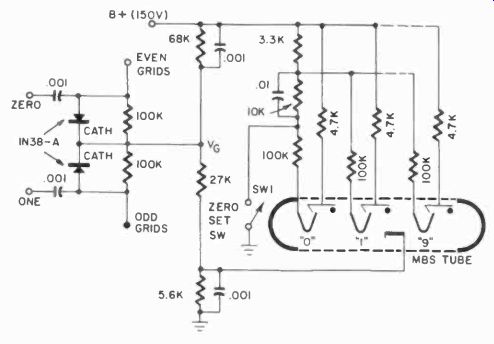
Fig. 512. Schematic of basic beam switching drive circuit.
In a previous Section we discussed magnetrons briefly. In the cutoff state, the electrons spin around the cathode in a circle (be cause of the magnetic field forces) following the equipotential force lines. This also takes place in a beam-switching tube when all the spades and targets are at equal potentials. In the magnetron, we disturb this state of spinning equilibrium by lowering the voltage on one plate, which then causes electrons to travel to that plate. In the beam-switching tube, we do the same thing. With a pulse, we lower the voltage on one spade and, as we do this, a "beam" of electrons will form to that particular spade and will lock in on its associated target.
The output voltage from the target is the useful output of the tube, which can be used to light a neon indicator tube or to control circuits with sensitive relays. In the latter case, the relay coil would take the place of the target resistor. If a beam has formed on a target and spade, we can remove the beam by making the associated grid strongly negative. But the beam cannot simply be interrupted. When we make it impossible for the beam to go to the present spade, with the grid cut off, because of the shape of the spades the beam will jump to the next spade in line. Notice in Fig. 511 that the "next" spade is physically closer to the previous spade -and -target -held -beam than the one before that, and the natural place for the beam to go is to this next spade. This is what happens when we switch with the grid rods. Alternate pulses must be obtained for even and odd grids, as shown in the basic circuit of Fig. 512. If we tie all the spade circuits together and then leave the grids at a constant potential, we can also switch by applying a positive pulse to the connected spades. After all, making the anode more positive, as far as the grid is concerned, is equivalent to making the grid more negative, if the stream from the cathode remains the same. Or to put it differently, if we make the lowered spade more positive, it will no longer make such a "dent" in the equipotential lines, and the beam will tend to jump to the next spade in line.
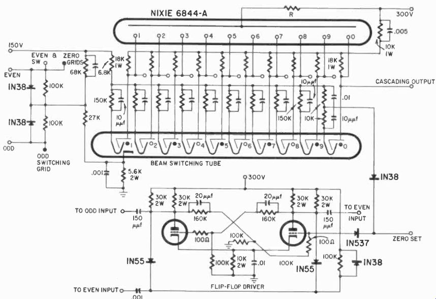
Fig. 513. One beam switching tube and one display tube make a simple and
compact counter decade.
Odd and even pulses for the grids are most readily obtained from our well known flip-flop circuit, and this is the way the tube is most often controlled. The schematic is shown in Fig. 513. The next beam -switching tube in line would then receive a starting pulse from this one, and thus we can use tubes for units, tens, hundreds, thousands, etc. and so make up a complete decimal counter. If the counting must take place very fast, we will not depend on the pulse from the beam -switching tube directly but, instead, make sure the pulse is large enough and brief enough by interposing a multivibrator between the tubes.
The Dekatron and the beam-switching tubes obviously lend themselves as well to circuitry with coincidence gates, and we can again make up preset counters which can control various industrial processes.
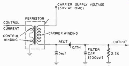
Fig. 514. Basic ferromagnetic amplifier. High-frequency ac is used far
a carrier.
In effect, the beam -switching tubes and Dekatrons are used as current distributors or nonmechanical switches in many ways, something which was difficult to do with flip-flops, and hence these tubes have a decided advantage. They are as fast as reliable flip flops, and they certainly require less parts per decade. They are also relatively expensive, but if Ave consider, as part of the cost of an instrument, all the labor needed to connect the circuits, then beam -switching tubes can provide a considerable saving in spite of their somewhat higher cost.
Other static switches
Next we will look at other forms of static switching, those not using vacuum tubes or transistors. The term static here means only that we use no moving parts, so here transistors and tubes are considered static switches.
The static switches we will now consider are those using magnetic principles. Certain magnetic materials have peculiar characteristics with respect to their magnetism. Two distinct kinds of devices are used, and both depend on magnetic properties. These magnetic devices usually consist of small toroidal cores of a particular material, with several windings on them. The characteristic upon which we depend is that the course of magnetization in these cores takes place in a manner that will permit linear control of an alternating current in one winding with a small dc variation in the other, on the same general principle as a magnetic amplifier.
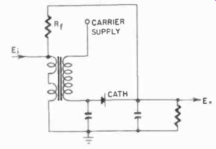
Fig. 515. Basic feedback circuit. Proper component values will make this
a bistable circuit.
The basic circuit is simplicity itself. In Fig. 514, a carrier current is applied to one winding. This can be an ac as high as 10 mhz per second. Through the other winding we can apply a direct variation of voltage or current, and the current in the secondary will vary with this primary current, which may be very small. If the carrier voltage which results is rectified, this will vary with the primary or control current. (See Section 8 for more de tails about magnetic amplifiers and static switching.) As in any magnetic device, when we make the control current great enough, the core will saturate, and then we cannot further increase the carrier current passed. This is a characteristic which we can use to make a bi-stable circuit. If we feed back a portion of the secondary current into the control winding and carefully adjust the value so that as the primary, and thus the secondary, current increases, this portion becomes sufficient to keep the core saturated. A pulse applied to the primary, if large enough, will lock the core in that magnetic condition. It would then take a negative pulse to unlock the core, after which the core will lock oppositely magnetized. This feedback loop is shown in Fig. 515.
The pulse which demagnetizes the core and starts the reverse magnetization must be rather large, and notice that the unit must have alternate negative and positive pulses.
Many variations of this circuit can be built with ferromagnetic units hut, although they are common in digital computers, they arc not really marketed in electronic counters as yet, again because of certain limitations. One circuit which can be developed from this is a free-running multivibrator in which the entire control current is obtained from the secondary. In Fig. 516 the primary current is fed back through a capacitor. Once the capacitor is charged, no more current will pass, and the unit will demagnetize until the capacitor is sufficiently discharged to start the cycle all over again. The size of the capacitor and the resistor will determine the timing of the circuit.
Many similar circuits can be built, but they are not yet common in industry. However, it may well be that these ferromagnetic devices present the best solution for the various kinds of atomic reactor control functions of the future.
Fig. 516. Pulse feedback makes a free-running multivibrator of the basic
ferristor circuit.
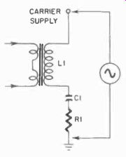
Fig. 517. Basic ferroresonant circuit is bistable because of its negative
resistance qualities.
Another way in which the ferromagnetic elements are used is called ferroresonance. In this, the secondary of the unit is circuited in series with a capacitor, and the control current varies the reactance of the core and secondary. When resonance is reached (Fig. 517), the current through the secondary is greatest and, with the proper values in the circuit, this can be a saturation current. This then is a ferroresonant point. The core will be maintained at saturation. However, although a trigger can start the swing toward saturation, it is not possible to de-saturate the core with a pulse, at least not directly through the control winding. To achieve this the voltage of the carrier must be lowered, which is analogous to extinguishing a thyratron.
This type of ferromagnetic circuit has two stable states, saturated and non-saturated. These states can be used to make flip-flop type circuits for counters.