AMAZON multi-meters discounts AMAZON oscilloscope discounts
AFTER our review of counter circuits in the previous Section it, may be well to reiterate that it does not cover all types of counting devices. For example, a recent transistor development, the Unijunction transistor, which is suitable for switching duties, will eventually make interesting and reliable counters. At this time, however, unijunction transistors are still expensive enough to receive a great deal of competition from vacuum-tube counters.
Then there is also the so-called "avalanche" transistor which employs a barrier layer of radioactive material and can switch so Fast that we have no way of measuring the transition time from one state to another. And there are other, much slower but nevertheless promising devices such as the electrolytic switch in which the application of a dc polarizing potential makes the electrolyte conducting to alternating current, while the removal of the do potential increases the resistance enormously. It is somewhat analogous to ferromagnetic switching devices.
There will continue to be advances in other directions. Transistor microcircuit developments have led to the manufacture of transistor flip-flops which can literally fit into the eye of a needle.
If such circuits become plentiful and inexpensive through mass production, spectacular developments can be anticipated in the field of electronic counters.
But no matter what the developments are in counters, the techniques for using them will change but little, since there are certain fundamental limitations on digital devices.
Simple counting
The most obvious use of counters, of course, is in simple counting. No matter what is being counted, the objects must in some way produce electric pulses which can activate the counter. These can be created by interrupting a light beam to a photocell, by switches being closed momentarily, by the objects, by sounds picked up by microphones and amplified to the proper input voltage or by variations in some form of transducer such as a piezo electric ceramic crystal, due to pressure changes, puffs of air or exhaust gas, or mechanical motions; by special pulse generators de signed for the purpose (as in tachometers), and by many other means. But, in essence, they all amount to one method. Mechanical forces, motions of objects or operations are counted by trans forming them into electrical pulses. Notice that in all cases motion is involved. We can count stationary objects, but in that case the "counter transducer" must be moved, at least in one direction and possibly in two or even three directions.
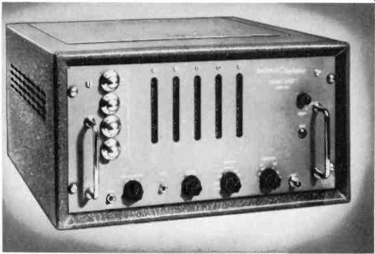
Fig. 601. Anything that can be converted to usable pulses can be counted
on the Events Per Unit Time (EPUT) meter. (Beckman. Inc.)
Simple counting is useful when we want to determine the number of items produced; or the number of operations a machine has carried out, in order that required maintenance schedules may be set up; or how many cars have passed into a parking lot to get an estimate of the business done in a shopping center, and so on.
A variation of 5% or 10% in the reading in such cases will probably not be alarming. But suppose that we are concerned with much greater accuracy--that we want to know much more precisely the number of items passing a given point in a specified period. In the first place, we will need to limit the time span to a very precise period. This can be accomplished by the use of (EPUT), Events Per Unit Time counters which have many useful applications (see Fig. 601).
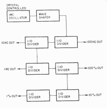
Fig. 602. Frequency-divider chain also reduces the possible error by the
amount the frequency is reduced.
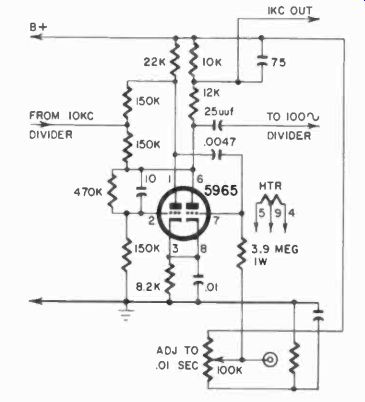
Fig. 603. Typical frequency-divider stage ran be used in many timing devices.
Applications for EPUT counters
Sonic counters have the time-measuring device built in whereas in others, it is an external accessory. Whichever is used, the timing device simply turns the counter off at the end of a specified interval after the starting signal. The timing device is often a crystal -controlled oscillator, followed by multivibrator frequency dividers. Fig. 602 shows a block diagram of such a timing chain, and Fig. 603, a typical multivibrator divider which divides by 10.
The great advantage of this system is the tremendous accuracy obtained. It is quite easy to obtain an accuracy of 1 part in 1,000,000 with a temperature stabilized, crystal -controlled oscillator. This .0001% accuracy is, of course, maintained through the divider chains. Thus, with a time span of 1 second, we can get an accuracy of 1 microsecond and, if we were counting 1 million events in this second, could obtain an accuracy with ± 1 count.
This means that with such a time -period accuracy the electronic counter becomes an excellent frequency meter, which is one of the most useful applications of the EPUT-type counter, Specially -made counters for this purpose can count up to 10 megacycles directly and can repeat their count each second, each 1/10 second or even faster. Thus it is possible to keep almost continuous track of frequency as fast as or faster than can be read on the indicators.
This counting rate can be extended almost indefinitely with an addition to the counter of a heterodyning device, which is illustrated in Fig. 604. This consists simply of a very accurate oscillator, which puts out a pulse form usable by the counter, and a mixer. The frequency to be measured is mixed with the oscillator frequency, and the resulting beat is counted. Thus if we have a 1-mhz counter and an oscillator which produces 15-mhz waves very accurately, we will be able to count from 14 to 16 mhz, with an ac curacy only limited by the precision of the heterodyning oscillator and the timing oscillator and dividers in the counter. Such EPUT counters are beginning to offer serious competition to other types of frequency meters in industry and laboratory. The photo in Fig. 604 shows an amplifier and converter combination designed for this work.
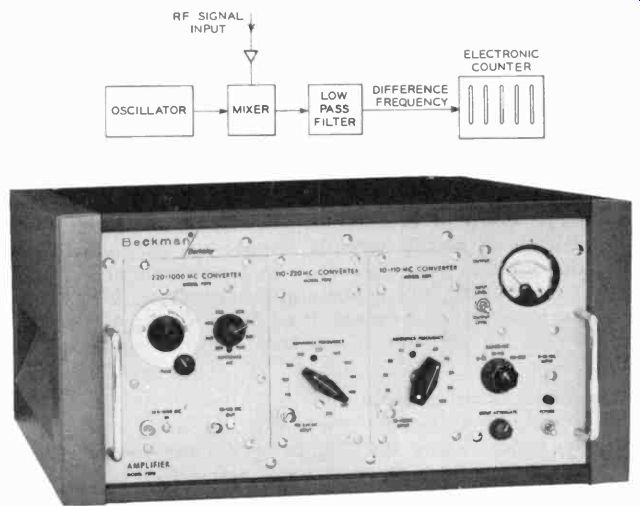
FFig. 604. It is necessary in heterodyne a high frequency that is not within
the frequency range of a counter. Stable oscillators can be included in
the same case. (Beckman. Inc.)
Another immediate application suggests itself: tachometers.
If we have a wheel with holes or a flywheel with a bright spot, either of which can periodically pass or reflect a light beam into a photocell as the wheel rotates, and if we count the number of pulses a second or minute, we have an accurate indication of the number of revolutions in that time. This is illustrated in Fig. 605.
There are many similar applications in which events per unit time are of consequence. If the number of units produced in a given time is known, simple multiplication will determine the total production from an average of several such samples.
If a flowing liquid has a small quantity of low-grade radioactive material added, we can, by calibrating and by counting the pulses which flow past a Geiger counter, measure the exact rate of flow of the liquid. With a low -energy radioactive source behind a rib bon of metal coming out of a rolling mill, we can, by keeping track of the count of pulses, determine the exact thickness of the material and regulate for uniformity.
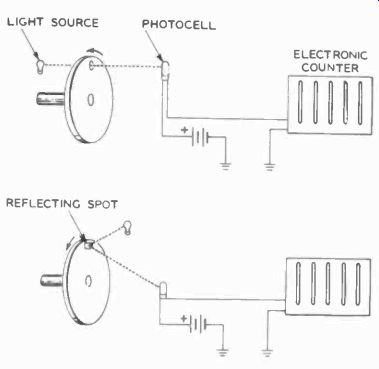
Fig. 605. Pulses of light can be converted into rpm with a counter.
All these applications are concerned with the number of pulses counted per unit time, and the reader can probably think of many others. However, we can make use of this idea in another way which is almost equally versatile.
Suppose we already know the number of pulses from our source, say a very accurate oscillator.
Then, by counting, we can establish the time lapse, from the beginning to the end of the count. If we design a setup in which one event turns on the counter and another turns it off, we have something new.
The time -interval counter The time-interval counter is a digital counter made up of decades, and has a gate which can be opened and closed. The gate is controlled not by an internal timing mechanism, but by an external signal. The input of the counter is then connected to an accurate oscillator, which we will call the "clock" oscillator. The counter will thus show the exact time that the gate is open, and provide an accurate count of the time lapse between opening and closing. Special time -interval counters have the "clock" built in, and in this case there is usually a choice of clock pulse from 1 mhz down to 1/100 second or less. The principle is illustrated in Fig. 606.
Such a counter can measure any lapsed time between two electrical events which fall within the capability of its count. Some of the applications of the time-interval counter are in pulse -generator calibration, relay timing, timing of photographic shutters, ballistic measurements, etc.
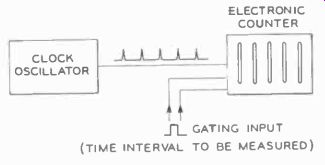
Fig. 606. When the clock oscillator frequency is a known value, it is
easy to compute the duration of the gate pulse.
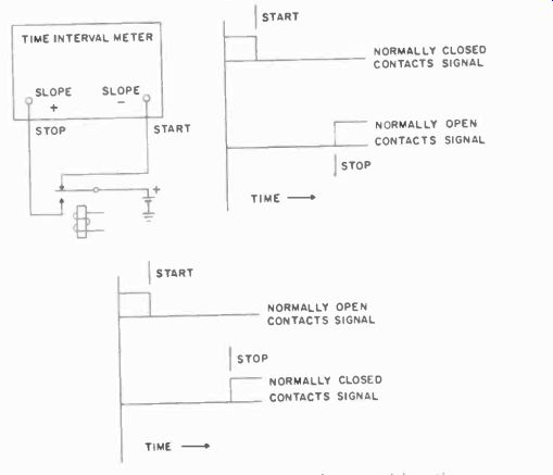
Fig. 607 shows the calibration of a relay, while Fig. 608 illustrates
a ballistic measurement.
The start pulse in the latter is obtained from the first photocell, while the stop pulse is generated when the projectile interrupts the beam to the second photocell.
Similar arrangements can be used for timing sporting events. The transducers need not be photocells. Fig. 609 shows another way of deriving the stop and start pulses for ballistic measurements.
Here a thin sheet of paper supports a fine wire grid and, when the projectile pierces the paper, the circuit is broken, starting the count. When the projectile pierces the second paper, the stop pulse is generated.
Fig. 607. Simple circuit measures relay transition time.
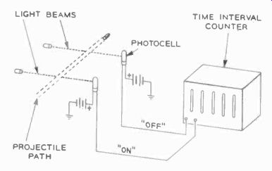
Fig. 608. The speeds of large projectiles are easily measured with photocells.
Fig. 610 illustrates the measurement of shutter timing. As indicated in the curve, the leading edge and trailing edge resulting from the rise and fall of the current in the photocell are sharply differentiated to provide the necessary on and off pulses.
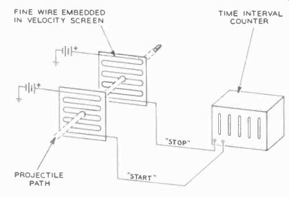
Fig. 609. This non-electronic circuit is Simpler but requires repair or
replacement of the velocity screen after each test.
There are numerous other applications for time-interval measurement; those shown are only a few examples. Timing is important in everything, from missile countdown to the heating cycle of a dielectric generator. Although you probably wouldn't use the electronic counter for the first, in the second case it would be used to check the accuracy of the standard timer.
The time-interval counter is as important an instrument for service work as the EPUT counter, and many electronic counters perform both functions. For the EPUT, a timing pulse from an accurate clock is needed, plus a gate which can be opened and closed, whereas the time -interval counter needs a gate which can be opened and a clock pulse which is counted. In essence the requirements are the same, and thus easily incorporated in a single counter.
Fig. 610. A photocell connected to a time-interval meter will check camera
shutter speed.
More common than either the EPUT or the time-interval counter is the preset counter. A preset counter is not shut off by an external clock (like a time-interval meter) or an internal clock (like the EPUT), but by its own operation. In Section V we mentioned briefly how presetting can be arranged with coincidence circuits, and gave a simple example of counting jelly beans before a bag of them is sealed. There are numerous more sophisticated, applications of the preset counter in industry. A preset counter can be used, for example, as an accurate timer, using a clock pulse. If the device, which starts the count, starts a clock oscillator, and the counter is preset for a certain number of counts, the counter will shut down after receiving the preset number of pulses from this oscillator.
Preset counters are useful in applications in which counting is irregular. A simple example would be the irradiation of a product to a certain precise level. An actual count from the output of a Geiger counter would give very close control over the amount of radiation.
An electronic counter can even be used to measure liquids if the proper kind of transducer is used with it. The magnetic flow meter in Fig. 611 is such a transducer. In this sensor, the liquid flows through the pipe and rotates a turbine, which contains a magnet, making the vanes magnetic also. As the vanes pass the coil, they create pulses in this coil, which are fed into the input of an electronic counter. The manufacturer of this transducer also makes counters to go with it, one of which is shown in Fig. 612.
Its ability to measure time, frequency and events accurately makes an electronic counter an almost universal instrument in a sense. Automation will make use of more of them for various operations.
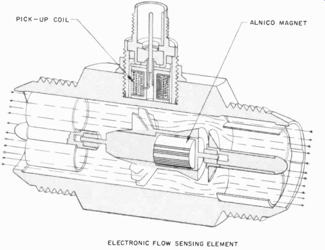

Fig. 611. Magnetic flowmeter generates pulses which can be counted as
a measure of liquid flow. Sensor must be calibrated for temperature and
viscosity of liquid.
Readout of counters
Anyone concerned with the maintenance of counters must be familiar with readout devices which display the count.
The count can be displayed by small neon tubes, and this is a very popular approach because it is inexpensive. But it does require relatively close reading, since the neon tubes are small and not very bright. For a bench type instrument, neon tubes are fine. But for displaying at a distance, something more easily read is needed.
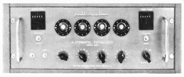
Fig. 612. A counter of this type indicates the rate of flow as well as
total flow. The reset counter is convenient to keep track of small quantities.
(Potter Aeronautical Corp.)
One of these readout devices is the Nixie tube, made by Burroughs. It is, in effect, 10 neon tubes in one. Each Nixie contains 10 cathodes, shaped like letters and superimposed one upon the other in such a way that, if any one cathode is "hot," its shape can be easily seen. The Nixie is strictly a readout device, doing no counting itself.
Incidentally, the Nixie tubes are also made with letters instead of numerals, which makes them suitable for spelling out words, but this is not for counter applications, except where these counter circuits are used in computers designed to give an immediate legible output.
Another system of readout calls for the use of numerals engraved on thin sheets of plastic. The figure shows clearly when the plastic is edge-lighted. Thus a stack of such sheets, each with a numeral, each edge lighted by a different bulb, will show the appropriate numeral as each bulb is switched on. If the plastic is a fluorescent type, the display can be very effective for large numerals, but an inverse relationship exists here: the larger the numeral, the more the brightness of the light will be dispersed and the less clear the numeral will appear (unless several lamps are used).
Another system used for readout is familiar from its use in display of time, temperature, etc. on buildings. The numerals are formed from a group of neon tubes so shaped that any numeral can be made from a limited number of straight sections. A special switching arrangement is required. Fig. 613 shows how numerals can be formed from only seven straight bars. Short neon tubes are used for the bars. Notice that the bars for 8 and 9 are almost the same, with the exception of one bar; that 5, 6, 8 and 9 differ by only one or two bars, etc.
Remembering that it took three flip-flop outputs to show unambiguously the state of a counter, you can easily see how we can use this fact, plus the state of the fourth flip-flop in the counter, to show such numerals.
Other ingenious kinds of readouts have been designed, using similar principles. For example, one development consists of small boxes with optical systems with miniature masks as well as sets of very small lamps. When a mask is lighted from behind it projects, on a small translucent screen, the number to be read out. This system has the advantage that it can be used for other things besides numbers: an entire message can be inscribed on the mask.
Troubleshooting and repair
Besides the customary test instruments used in repairing electronic equipment, two additional items are needed for the repair of electronic counters generally. One is a pulse source accurately calibrated to frequency, or a crystal oscillator of an accurate frequency within the capability of the counter, and with some way of differentiating the waveform from the oscillator. The latter may be accomplished readily by using a very small capacitor and a large resistor. Often the counters will accept the sine wave from the oscillator, and have the pulse-forming circuits built right into the instrument.
The second unusual item needed is an accurate timer which falls within the range of the counter requirements, and one which can turn the counter gate circuits on and off precisely. The uses of these two units are obvious from the preceding discussion.
Electronic counters, like any other complicated piece of equipment, come equipped with a complete service manual. If the counter is a regular item in the equipment under your care, you'd do well to get acquainted with this manual long before the actual need arises, thus saving time on repair when the equipment does break down.
It should be noted that decades never count at the same rate; they differ by a factor of 10. The fastest is the Units counter, and each decade is 1/10 the speed of the previous decade.
When a counter tube begins to deteriorate--if, for example, it has become slightly gassy--it will not be able to count as fast as one in perfect shape.
Fortunately most counters have identical decades. One of the ways in which we can often avoid having to use new parts is to switch decades. Insert perfect ones in the fastest spots, and those which refuse to work at top speed, in the slower ones.
This swapping is also a way of rapidly testing for trouble spots.
If a counter still does not work after switching the first and last decades around, chances are that the decades may be all right.
But if it works up to the decade which used to be the units one and then stops, it is a sure indication that there is trouble in this decade. Follow this procedure to test any of the decades, swap them around to see if the behavior of the counter is any different.
Outright cessation of counting can be caused by faulty coincidence tubes in the models that have them. The coincidence tube (Fig. 503), is normally left connected to the plate circuit of the first tube in each flip-flop. If it becomes gassy, it can effectively absorb the output pulse and stop the whole decade. This is one of the first places to look for failure.
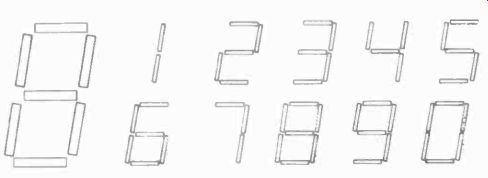
Fig. 613. Numerals of this type are displayed by neon tubes or electroluminescent
display devices.
Next, the decade tubes themselves should be tested and replaced if necessary. Weak tubes will not produce sufficient output voltage to pulse the next decade. A replacement tube should operate properly without any special selection. Binaries are usually designed with adequate leeway for this reason.
Power supply voltages are relatively critical and should be checked when the whole set of decades show erratic operation.
With an oscilloscope it is easy to establish whether the input circuit is operating properly. If it is, the trouble in the counter is either in the decades, the power supply circuits or even in the readout. It is quite conceivable that the decades may be working all right but the neon tubes remain dark because of a tube failure.
This can be readily established with the aid of a small neon tube of the proper voltage limits. Preferably, if the counter uses neon tubes, an identical tube should be kept for testing the readout circuits. Or, with the counter off, a voltage can be connected across the readout tubes to determine whether they are functioning properly.
Next, make certain that the input pulse has the proper size and shape. Usually the input pulse-forming stages take the form of a Schmitt trigger circuit, which has the happy faculty of always producing the same kind of pulses from any input -signal wave form. The Schmitt trigger circuit is a type of cathode-coupled multivibrator, but its operation is a little different than the usual binary. Fig. 614 shows a basic Schmitt trigger. This one uses triodes; often pentodes are used for fast response, but the operation is basically the same.
The circuit (Fig. 614) has two states, as does any bi-stable multivibrator. Assume that the voltage on grid of V1 is such that the tube is cut off. This means V2 is conducting. The plate of V1 will be at supply voltage potential and, through divider R1, R3, R4, the grid of V2 will be at a relatively high voltage. The cathode of this tube, V2, which now operates as a cathode follower, will be at a slightly higher voltage than its grid: of course, the cathode voltage of V1 is the same. If we now raise the input voltage gradually, V1 will start to conduct when we reach a point slightly below the cathode voltage on V1. This will lower the voltage on its plate, and with it the voltage on the grid of V2, which now conducts a little less. If we continue raising the input voltage, V1 will conduct more and more. This also raises the cathode voltage of the two tubes.
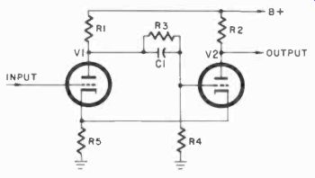
Fig. 614. Basic Schmitt trigger circuit is used to generate uniform pulses
from various input waveforms.
At a certain point, the voltage on the grid of V2, which is gradually lowering and the cathode voltage which is gradually rising, will reach a point where V2 is cut off. Immediately, the voltage on the cathode of the tubes drops sharply, allowing V1 to conduct heavily. But V2, which normally would be expected also to begin conducting again at this lowered cathode voltage, cannot do so because its grid is held at a lower voltage by the charge stored in capacitor C1.
Thus V1 has taken over conduction, and now the trigger circuit has changed state. This would register at the plate of V2, where we take the output, as a sharp rise in voltage. Now when we start lowering the input voltage, we will reverse the process, making V1 less conducting and raising the grid voltage on V2. At a certain point, we will reach the grid voltage on V2 which will allow this tube to start conducting a little, and it will suddenly take over conduction in the same way. The grid of V1 is held low by the low input voltage and, in spite of the lowered cathode voltage when V1 cuts off, it cannot conduct again. V2 takes over and the circuit is back to its original state.
At the plate of V2 this second change of state registers as a sharp drop in voltage (when V2 conducts again), and thus we have formed a pulse. This pulse will always have the same amplitude and the same rise and fall time (unless we drive the Schmitt with a very short pulse). The duration of the pulse will depend only on when these two points, at which the respective tubes started to conduct, are crossed, once on the way up with the input voltage and once on the way down. These two points are known as hysteresis points, for the obvious reason that this circuit acts, to all intents and purposes, as a piece of iron being magnetized in regard to the sudden changes of state and the "lag" in change of state with the change in input voltage.
The pulse length, produced by the Schmitt trigger, is usually adjusted by providing the grids with adjustable bias, so that the hysteresis limits can be accurately preset. Obviously, a very small change in voltage can flip the Schmitt if we set the hysteresis limits close, and this is what makes this such a useful pulse-forming circuit. If the circuit has to be energized with very small voltages, it is generally preceded by a simple amplifier, and sometimes with a cathode follower before that to avoid loading the input circuit.
Counters, in theory, don't present much serious difficulty basically - in practice, they are usually built in as small a space as is feasible and, although the decades are often plug-in devices which can be removed as a unit, the rest of the counter is quite crowded and may present some problems in checking the circuits. An extension cable would help here. In some cases, it might be better to set up a power supply and a spare socket of the proper circuit connections for the external testing of decades. This is strongly recommended if your work will require frequent servicing of a group of counters and will save considerable time.
What has been said about swapping decades is as valid for the various kinds of counter tubes. These, too, can be swapped to find the sick one. Obviously, the units counter here must also do a much faster job, so that, if it slows down through aging (and this does happen), then it can be used in a slower circuit, with a new one or one of the other tubes taking its place.
When removing and inserting counter tubes, particularly the beam -switching tubes, be very careful not to bend any pins. If you have ever had trouble inserting a seven-pin or nine-pin miniature, you will appreciate what it means to have 26 pins on a tube not much larger. Because of the heavy magnet around the tubes, shocks to the instrument are more likely to unseat the tubes, and this is something to keep well in mind when transporting these instruments.
Outside of such special tricks as swapping decades and the particular care in handling decade tubes, electronic counters should be treated like any other complex electronic instrument.
Periodically, the tubes should be checked if the counter is used continuously. Among the most likely thing to go wrong with a counter is that one of the flip-flops will stop changing state; these are the most critical items in the instrument. For the rest, your treatment of the counter will depend on whether you subscribe to the philosophy that it is better to leave equipment alone so long as it is functioning well, or whether you are of the school that believes in preventive maintenance. In general, in the military services and in industry, the leave-it-alone philosophy is gaining favor as the more economical of the two in the long run.
And, of course, as with all electronic equipment, cleanliness is the first order of maintenance.