AMAZON multi-meters discounts AMAZON oscilloscope discounts
MANY electronic controls used in industry have a relay or contactor as the final link in the chain. These relays come in many shapes, sizes and forms as a glance at Fig. 701 shows.
Generally speaking, the relays dealt with in industry will be of moderate size. The majority will be open types mounted in cabinets along with other equipment, and only a few will have special sensitivity and coil ratings or unusual contacts such as one type designed to handle very high voltages.
A relay is any device whose contacts are opened and closed by electrical means (whether this be a coil, a heated bi-metal strip, a meter -movement type of rotating coil, an expanding ceramic' element or a motor type of disc) in order to control another circuit.
Most prevalent are the coil types, and we need say little about these except that there is a basic difference between the ac and dc forms. One difference is that the ac type must contain some means of avoiding armature chatter, and this usually takes the form of a shorted turn called a "shaded" pole. The shorted turn shifts part of the magnetic field in phase so that, when the main current through the coil, goes through zero, there will still be more magnetic field to hold the armature to the core.
Dc and ac relays have different maintenance problems. In dc coils there will be corrosion, due to electrolysis; in ac relays this presents no problem. In ac relays, on the other hand, you will find problems such as shorted turns which can drastically affect the operation of the relay (since the core will give it the character of a transformer with shorted secondary). Contacts carrying dc are more likely to arc, with resultant uneven burning and pitting. Ac voltage peaks are passed in a fraction of a cycle, but a dc arc continues to build up. In ac relays, the coil current is drastically reduced when the armature closes completely while in dc coils it decreases very little. Therefore, dc relays remaining energized for long periods of time show more tendency to heat.
Fig. 702 shows some telephone type relays, which are in a class by themselves, but are likely to be encountered in electronic controls because their flexibility of contact arrangement makes them specially suited to this kind of work. Also the frame configuration of telephone type relays lends itself to the construction of sensitive units with high coil impedances and resultant low current requirements.
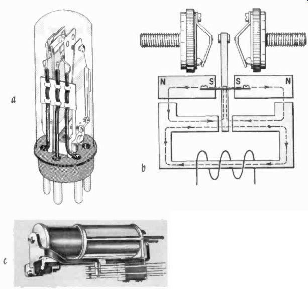
Fig. 701. Enclosed plug-in relay (a) makes maintenance simple. Polarized
relay (b) has a center-off position and can be adjusted for latching. Sensitive
telephone type (c) can control many circuits.
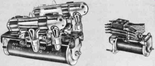
Fig. 702. Telephone type construction can tilt mercury tube contacts or
operate many dry contacts.
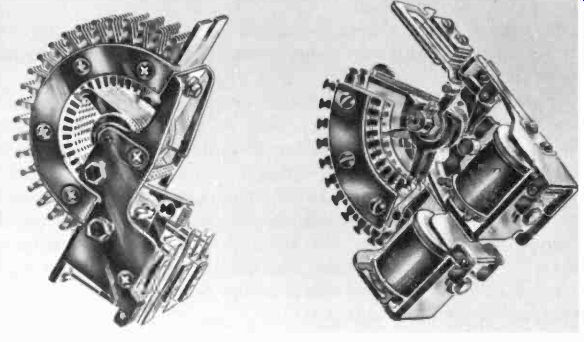
Fig. 703. Stepping relays are digital since stepping pulses are also digital.
Relays in control functions are digital devices, since they have two states, either on or off- there is no halfway point. Also in the class of digital switching devices are the various stepping switches.
some of which are shown in Figs. 703 and 704. Those in Fig. 703 are familiar in telephone circuitry, and some of them contain many hundreds of contacts in banks of 11, 22, 36 or 45. The one at the right is a 10 -point switch which has a spring reset mechanism; the other rotates continuously, bringing a new set of rotating contacts onto the stationary contacts every 180 degrees.
There are many other versions of these switches, some of them capable of rotating in two directions. One of the oldest and most used of this type is the Strowger switch (Fig. 705--contact banks have been shown separately for clarity) which has two motions.
The vertical motion selects the appropriate bank of contacts while the horizontal rotary motion selects one contact in that bank.
The relays mounted on the frame control these motions, with appropriate timing so that the switch can respond to two sequences of digital signal, one sequence for each motion. After the motions have been completed or, if too much time passes between motion signals, a single pulse allows the switch to step to home position.
Strowger switches are useful where more than 100 contact points must be dealt with.
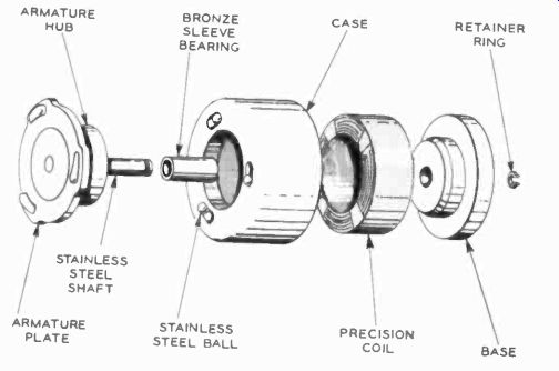
Fig. 704. Rotary solenoid can be used to drive many rotary switch decks.
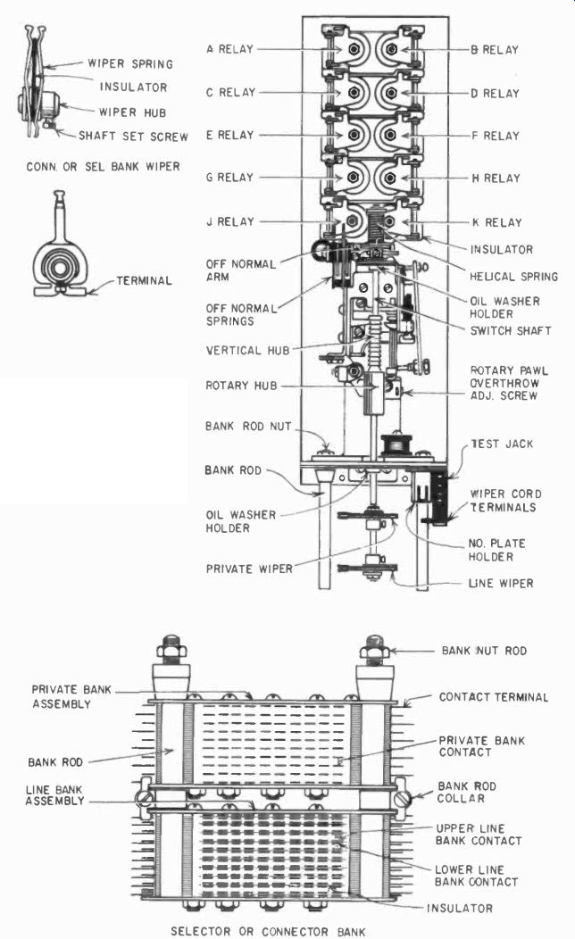
Fig. 705. The two-motion Strowger switch is actuated by two series of
digital pulses which select from several hundred contacts.
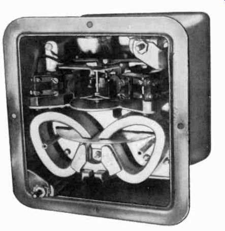
Fig. 706. Eddy-current disc motor is strong enough to operate contacts
in this time-delay device.
The switch in Fig. 704 is the well known LEDEX type, which uses a rotary solenoid to step points on ordinary rotary switch decks. This allows any combination of available switch sequences, with shorting or non-shorting contacts as desired. The LEDEX solenoid depends on the mechanical motion executed by a linearly moving slug in a coil, and a slanted disc attached to this slug. As the slug is attracted deeper into the coil, the disc, which rolls on steel balls, will tend to rotate because this is the only motion which will allow the slug to travel to the bottom of the coil. The race on which the balls run is slanted.
In the power-generating and transmission business we also have what are called "electronic relays," a version of protective relay used to protect sections of transmission lines.
Relays which are oversized are no longer classified as relays; we then call them "contactors." Basically there is no difference. Contactors which must handle large loads are supplied with a means of extinguishing arcs, and this may take the form of magnetic "blowout" coils. Arc is a stream of ions and such a stream of ions can be affected by a magnetic field.
Another blowout means is a special arc chute which operates on the principle that the arc heats the air surrounding the contacts and thus tends literally to "blow" out the arc. When the loads which contactors are rated to handle are exceeded, heavy -current switches, called circuit breakers, (electrically or mechanically operated) are used. This is getting pretty well out of the class of electronic controls except where the "sensing means" for determining whether the breaker should be closed or open are electronic.
Relays do not always operate rapidly, and they are, in fact, classified according to how fast they must operate. Thus telephone type relays are slowed down by adding slugs to the core above or below the coil. Such slugs, when mounted at the armature end, will cause delayed opening of the relay; at the other end or "heel" of the relay frame they will delay closing. Such a copper slug at each end of the central core will make the relay operate slowly on both motions.
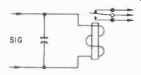
Fig. 707. Simple time delay is had by paralleling relay coil with large
value of capacitance. Charge holds relay closed after voltage is removed.
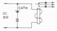
Fig. 708. Proportional -delay relay circuit. Hold -in depends on reverse
-current charging of capacitor. Relay hold -in is proportional to duration
of signal.
Other ways of slowing down relays consist of thermal means, such as separate bi-metallic contacts heated by the same current which will eventually hold the relay energized, or mechanical dashpots with air or oil. All of these are fairly familiar in industry.
For example, the Amperex series of time-delay relays (a thermal type of relay mounted in a tube envelope) can be obtained for many delay times and is often used to protect equipment against operating with unheated filaments (which might rapidly evaporate the filaments when high voltage is applied). Fig. 701-a is a relay of this type.
Of much greater interest here are the electronic means of obtaining time delays for relays, and this will be our first look at electronic controls. These will generally be dc relays, in contrast with the inherently delayed relay of Fig. 706 which works on ac on the same principle as your home electric meter, with contacts made by a pusher on the rotating eddy -current disc.
Electronic time delays
The simplest form of electronic time delay is shown in Fig. 707.
It consists simply of a large electrolytic capacitor in parallel with the relay coil. Delays of up to a second can be obtained this way.
If the applied voltage is always the same and the duration of the applied voltage is either always the same or more than long enough to charge the capacitor fully, this kind of delay can be quite dependable so long as the capacitor does not deteriorate.
To make a distinction between a short timing delay and a long duration signal, the circuit of Fig. 708 will serve. If the applied voltage is only of very short duration, the relay will drop quite rapidly. If the applied voltage remains on for a considerable time, the capacitor will charge enough to hold the relay for some time after the applied voltage is removed.
A delayed make circuit is shown in Fig. 709. When the switch is first closed, B is at exactly half of the battery voltage but, since it takes time for the capacitor to charge, point A is initially at zero. As the capacitor charges through R1, the potential at B and at the other end of the coil gets progressively more positive but, since the cathode of the rectifier is yet more positive than the anode, no current will flow. Only when the capacitor is fully charged will A be more positive than B, and current will suddenly flow through the relay, energizing it. For an adjustable delay, R1 can be made variable. The capacitor should be quite large for long time delays.
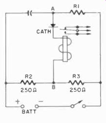
Fig. 709. Delayed make relay. See text for description of operation.
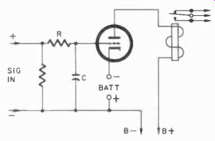
Fig. 710. Simple electronic SIG delay circuit depends on IN charging time
of capacitor C.
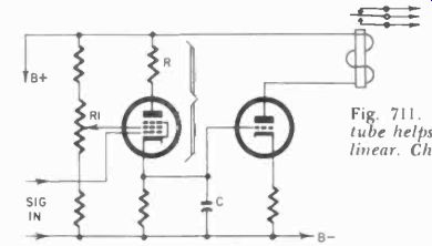
Fig. 711. Pentode charging tube helps make time delay linear. Charging
rate is set by R1.
Fig. 712. AC-powered time delay circuit. Triode is also rectifier to
provide bias.
Timing by charging capacitors is a relatively old subject to most readers who understand electronics. Thus the circuit of Fig. 710 is quite familiar. In this circuit, the capacitor must be charged by dc until the voltage on it is sufficient to overcome the negative grid bias, whereupon the tube will conduct and energize the relay.
This same operation can be made linear in time by using a charging tube (Fig. 711) but the principle is basically the same.
In industry, however, we deal most often with ac, and we would like to save components if we can. Thus, if we can operate a timing relay without first converting all the ac needed into dc, we can save a lot of money when making large quantities. Such an operating principle is shown in Fig. 712. Here we "misuse" the triode by operating the grid as an anode when the switch is not on, and in this way charge the capacitor C1 to a potential controlled by R1. The high -ohmic resistance R1 will tend to discharge the capacitor and the time required for this resistor to discharge the capacitor is a function of the potential to which we allow it to be charged: the higher the potential, the longer the time constant.
Thus, when the switch is closed, the tube will have a high negative bias imposed on the grid, superimposed on the alternating voltages of the circuit, and not until the potential across C1 has dropped enough to allow the tube to conduct on positive half-cycles will the relay energize. This is a quite simple and common circuit in industrial timers.
Had the switch been incorporated in the bias charging circuit instead, we could then get the opposite effect - the relay would he energized until the switch was closed, and the relay would drop out after a sufficient charging time had elapsed. Such circuit variants are also available commercially.
An entirely different principle of time delay involves the use of thermistor beads of sintered material, often a semiconductor material, which have the characteristic that their resistance drops sharply as their temperature rises. Thus, in the circuit of Fig. 713, the current through the relay will be insufficient until the thermistor has heated up. Variable time -delay can be had by making the heater current variable, so that it takes more time to heat the thermistor. Complicated electronic circuits can also be built with the thermistor as the regulating element.
Note that no matter what kind of electronic control of time has been discussed, it always involves some process which in itself takes time, such as heating an object, or filling or discharging some kind of reservoir, liquid, gas or what have you.
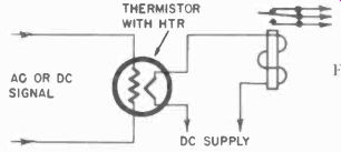
Fig. 713. Basic thermistor time -delay circuit.
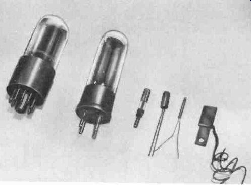
Fig. 714. Photosensitive devices have many forms.
Photoelectric controls
It is possible to go on ad infinitum discussing relays, but there are many other classes of controls to be included. Among these are photoelectric controls. These can also be simple or complex, depending on need, but industry will generally choose only those circuits which have very high reliability. A man's life or safety of limb may well depend on proper functioning.
The simplest means of control would be a photovoltaic cell, generating its own voltage as the result of the impinging light.
Such cells are used in photo exposure meters, for example. Until the invention of solar batteries, few voltaic cells gave enough output for reliable control work; consequently, not many applications of solar cells are to be found in industry.
Most of the photoelectric controls we will examine wall deal with photoemissive cells, the well known phototubes. These release electrons from a cathode as the result of light impinging on it, and these electrons are in turn attracted to the high voltage applied to the anode.
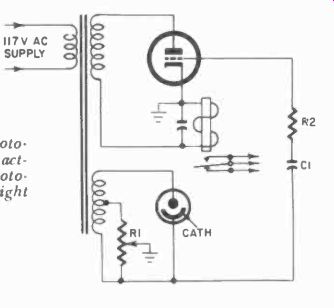
Fig. 715. Typical ac-powered photo electric relay circuit. Triode grid,
acting as diode plate, charges C1. Phototube discharges capacitor when
light strikes cathode.
Also important are photoconductive cells made from certain semiconductor materials which drastically change their resistance when the element is exposed to light. Typical materials used are germanium, silicon and cadmium sulfide. The last is most important because it can respond to a wide range of radiation, from infrared up to X-rays. Cadmium sulfide detectors are also used in industrial installations for X-ray dosage measurement. Fig. 714 shows some phototubes and typical germanium and cadmium sulfide photocells. Note the small size of some of the units.
Industrial circuits in the past have used mostly photoemissive cells. Fig. 715 shows a typical industrial photoelectric circuit, which differs from the usual experimenter's circuit in that it uses ac directly, even on the phototube itself. Here again the unit uses the triode grid to charge a capacitor, and the charge on the capacitor depends on the setting of R1. If light falls on the phototube, it will try to discharge the capacitor on the next positive half-cycle but does not succeed at once. But, as the phototube keeps discharging and the capacitor gets only a half -cycle to restore what is lost by grid rectification (which is a very slow way of charging), the capacitor will eventually be discharged sufficiently (and the bias will be reduced sufficiently) to allow tube current to flow and the relay to be energized. As long as there is sufficient light to keep the capacitor from recharging enough to reach cutoff bias, the relay will re main energized.
Similar relays may use thyratrons instead of triodes. One such circuit is shown in Fig. 716. Here the grid of the thyratron is, on the positive half-cycles, more negative than the cathode, and the tube remains cut off. When light falls on the phototube and the cell conducts, the grid will be made more positive by the drop across R4, and the thyratron will conduct. As soon as the light is removed, the relay will be de-energized.
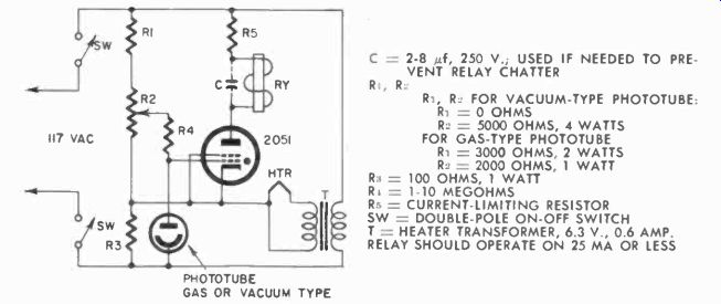
Fig. 716. Ac -powered thyratron photoelectric relay circuit energizes
relay when light hits photo-tube.
A similar circuit operating on a decrease of light is shown in Fig. 717, and its action is self-explanatory. Quite often in industry photoelectric circuits are used to compare brightness or reflectance of colors. This can be done with the circuit shown in Fig. 718.
Because we usually are dealing with very small differences in these cases--in fact, often differences which the human eye cannot detect--a dc circuit is used. Ac circuits with phototubes are fine for on-off action, such as the relay circuits we have shown, but when it comes to sensitive measurement, say with a meter, as the 100-pa meter in Fig. 718, then the use of dc is obviously an advantage.
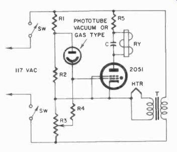
Fig. 717. Similar to Fig. 716. grid circuit changes cause relay to be
energized when light is rut off from phototube.
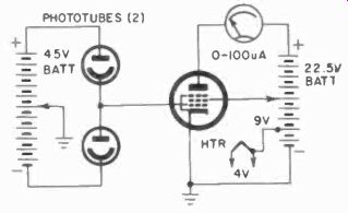
Fig. 718. This comparison circuit measures relative light intensities.
The meter could, of course, be replaced with a sensitive relay set to activate other circuits when the meter type relay swings one way or the other. This system is often used to accept or reject products by matching them with a standard. Sometimes fruit is inspected for color this way, and if color or ripeness is an indication of grade, the fruit may be sorted into categories by several circuits, one after another.
Photoelectric relays are frequently used to prevent injury to press operators-the press cannot operate so long as the operator has his arm in the multiple path of a light beam that must reach the phototube. Less important but often encountered are the photoelectric door openers in markets and restaurants, department and drug stores, etc. Similarly, phototubes, operated by daylight, turn plant lighting and road lights on and off.
Electric motor controls
In industry polyphase ac motors are preferred when certain ratings are exceeded, because they are more economical, both in terms of power efficiency as well as in the motor design itself. Thus for a given power rating, the polyphase induction motor, invented by Tesla, requires less iron and less copper than other types, with a resulting decrease in losses in the form of heat. Incidentally, the reason for using 60 cycles stems from the fact that Tesla calculated that at 60 cycles the precise optimum point is achieved in terms of iron losses in motors and generators.
Polyphase induction motors come basically in two types, the squirrel cage with one or more "shorted" windings in the armature and the so-called "wound rotor." The squirrel-cage motor is not intrinsically limited in size; but the motor has one disadvantage which becomes very significant in large motors. The initial surge of starting current in a squirrel-cage motor is as much as ten times the normal operating current. In dealing with a motor larger than 5-hp this becomes a serious factor, though still permissible.
Above 100-hp, most utility companies prohibit starting a squirrel-cage induction motor directly across the power line to prevent system damage. In such cases the motor is started at about 65% of normal line voltage, and, draws much less current. Resistors can be used for this purpose, but these waste power. Generally it is more efficient to use an autotransformer for starting.
Now when we get up into several hundreds of horsepower, there is theoretically no reason why the same system could not be used. In practice the currents become so large that auto-transformers become too bulky, and very expensive. For this reason, wound-rotor polyphase induction motors are used at these higher ratings and they possess the advantages of positive control of starting current as well as speed by controlling the current in the wound-rotor (field) windings.
Wound-rotor ac motors in small sizes would be very expensive.
Therefore, when accurate speed control is required at lower power ratings dc motors are used instead. In dc motors the motor speed is controlled by varying the armature current or the field current or both.
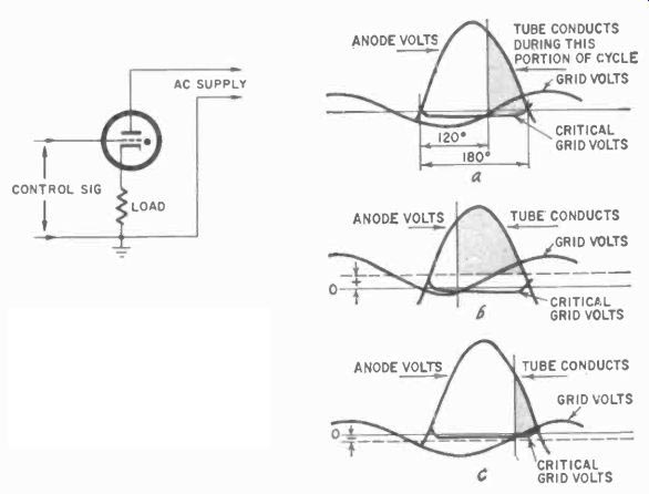
Fig. 719. Phasing of ac signal on grid controls the portion of half -cycle
where conduction starts.
There are many other ways to control speed in machinery, other than by actually controlling the motors, but they universally have the disadvantage that the control must be gradual. For example, a number of excellent variable-speed controls use variable-depth V-pulleys, which are very reliable and do control a wide range of speeds, but to change the speed from one extreme to another takes some time, whereas electrically it can be done very rapidly.
In many applications, motors in industry must have very rapid, continuously controlled variable speeds. Such applications are generally found in factories dealing with continuous processes such as steel rolling mills and paper, textile and wire mills, and in many other industrial conveyor systems, to mention a few. Electronic controls have solved many of their long standing problems, enabling an enormous speedup of many such processes.
Electronics, through the use of rectifiers, provides us with a ready means to control dc motors or the direct current in the field winding of large ac motors. By controlling the amount of current a rectifier passes, we have immediate control over the average direct current fed to the load. A number of devices can be used for this control, depending on the size of the current dealt with.
For the smaller loads, high-vacuum tubes can be used, but these have the disadvantage that the current through them must pass through a relatively high internal resistance. Even many tubes in parallel and with specially low internal resistance would have prohibitive total resistance for large currents. In such cases, thyratrons, handling up to several hundreds of amps, are utilized.
Above these capacities we turn to ignitrons, a similar device operating on a somewhat different principle. Finally, for extremely heavy currents, mercury -pool rectifiers are employed. However, these are not often controlled electronically as are thyratrons and ignitrons. In certain industries, such as the aluminum industry, complicated and ingenious controls are used for mercury -pool rectifiers, but these are beyond the scope of this volume.
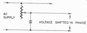
Fig. 720. Simple variable phase-shaft network uses capacitor and variable
resistor.
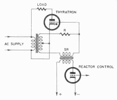
Fig. 721. This circuit uses a saturable reactor to control phase shift
of signal applied to thyratron grid.
Let us turn next to thyratron control circuits, the principle of which is illustrated in Fig. 719. As the voltage on the plate goes through its positive excursion, the point at which the tube con - ducts depends entirely on the voltage on the grid. We can control this in two ways, by voltage and by phase. Voltage control would require dc on the grid. For this reason ac phase -shift is more generally used to control thyratrons.
There are various methods of controlling the phase of the grid voltage. One is to use a capacitor and resistor in series across the ac supply and to tap off the phase -shifted voltage at their junction point. If the impedances of the capacitor and resistor are exactly the same, we will get exactly 90° of phase shift. Theoretically, this circuit could give us a shift of 180-degrees. Practically it is much less for, as the resistor is made smaller, the voltage across it is also reduced until it becomes zero. In Fact one of the major disadvantages of the method is that it does not produce a constant voltage. Variation of the capacitance in the circuit has the same effect (Fig. 720).
Another way to do the job is to replace the capacitance with an inductance and, if we use a saturable reactor as in Fig. 721, we have a ready means of varying the inductance. (Details of saturable reactor functions are discussed in Section 8.) Here again we still have the problem of varying control voltage, but we do have an extremely rapid means of control.
And, finally, if three-phase voltages are available, another way to obtain phase shift is with a selsyn in which the three-phase field can be made to induce a voltage of any phase on the secondary, which can be rotated either by hand or by motor.
Since the R-C method is the least expensive, we cure this system of its major fault, by using two sets, in the quadrature circuit of Fig. 722, which now shifts the phase one half in each section and has a constant voltage output.
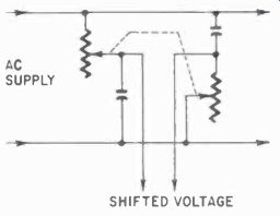
Fig. 722. Phase-shifted voltage output from this dual circuit is quite
constant.
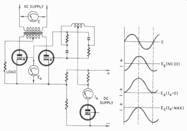
Fig. 723. This thyratron circuit has a fixed phase shift and a variable
dc bias controlled by the vacuum tube. Waveforms show effect of bias variations
and relation to thyratron plate voltage.
Controlling phase with a resistor would require manual or electrical control of a dual potentiometer or rheostat, and this would soon wear out. To make the system more durable (and more convenient), a system with a constant phase shift, combined with a variable dc voltage for control, is used. The circuit is shown in Fig. 723 and the waveforms at the thyratron show clearly what is happening. The top of Fig. 724 shows the normal course of waveforms with phase -shift control, and at the bottom, with fixed phase shift and variable dc voltage. As far as firing the thyratron is concerned there is no difference in effect.
Another feature of both phase-shift and voltage control of thyratrons shows up clearly in Fig. 724. The curve representing the grid voltage crosses the cutoff line at a very obtuse angle _. This means that, with a slight variation in thyratron characteristics, the actual firing point might vary quite a bit. To obtain firing accuracy we must employ a means to sharpen this firing-point definitely. This we can do with a peaking transformer. A peaking transformer is one which has a great deal more current forced through the primary than is needed for the load. When the current reaches positive or negative peaks, this will saturate the core.
A voltage will then be obtained from this transformer only when the core is changing from one state of saturation to another. The resultant secondary current is sharply peaked (Fig. 725). A very inefficient transformer, true, but a useful one for our purposes.
How we use this transformer in thyratron control is shown in Fig. 726. When the switch is opened, the capacitor in the cathode will gradually discharge. When the cathode voltage becomes low enough, the peak superimposed on the control voltage will fire the thyratron at a precise point. This is a very practical and very common means of controlling thyratrons and ignitrons.
A typical control circuit for thyratrons or ignitrons is shown in simplified form in Fig. 727. The cathode of the thyratron and its grid are connected by three transformers in series. T1 is a peaking transformer which obtains its primary current from a phase -shift network. The primary of T3 is out -of-phase and prevents firing of the thyratron, and the primary of T2 is in-phase (with anode voltage) and tends to help fire the thyratron. When the signal for firing is transmitted, the secondary of T2 will overcome the voltage on T3, and the combination of the difference and the peak from T1 will accurately fire the thyratron.
CONTROL BY PHASE SHIFT OF CONSTANT VOLTAGE VECTOR CONTROL BY FIXED VECTOR a DC VOLTAGE VARIATION
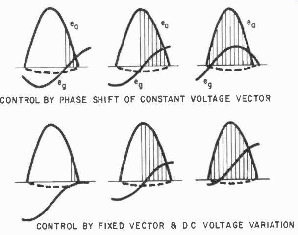
Fig.
724. Comparing pure phase -shift and combination phase-shift voltage firing
of thyratrons. Note that in both cases the grid voltage curve passes the
firing point at a very obtuse angle.
These circuits, and some others like them, form the basis of control through thyratrons or similar gas tubes. The output of the circuits used with the thyratron is a pulsating dc. If it is possible to use these circuits with three-phase primary current and fire three thyratrons in sequence as the phase becomes appropriate, we will smooth out the dc a great deal.
With this controlled dc, we can regulate the speed of dc motors or the field current for ac wound -rotor motors. We can also use them to control the dc control current for saturable reactors and magnetic amplifiers ( Section 8).
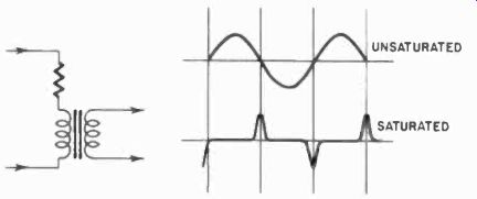
Fig. 725. A peaking transformer is saturated and produces secondary voltages
only when changing from one state of saturation to the other. The low impedance
of the saturated transformer requires a series current-limiting resistor.
A typical thyratron speed regulator circuit, the GE Thymotrol, is shown in Fig. 728. Both the armature and field current of the dc motor are controlled, each by a set of full -wave thyratron rectifiers, V1 through V4. Note in the diagram that the primaries and secondaries of various transformers are well separated, as was explained in Section 2. This is a more convenient notation to obtain functional progress through the diagram. The grids of V1, V4 and V2, V3 are controlled by the saturable-reactor phase-shifting circuits SRA and SRF, respectively. VI and V4 are controlled by T3, the primary of which (T3p) is in bridge SRA, and of V2 and V3, by the secondary of T4. Increased current in the saturable reactors will increase armature and field currents.
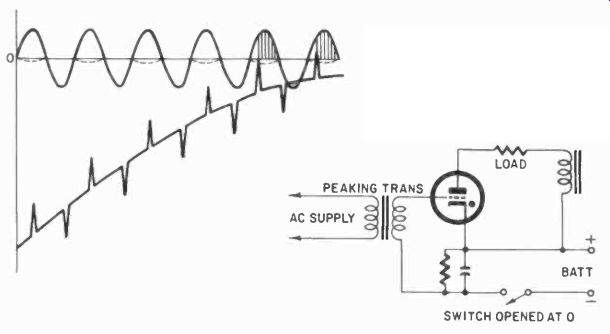
Fig. 726. This schematic shows peaking transformer uses dc bias for more
accurate firing of thyratron. Waveform indicates grid voltage action.
In addition to the phase shift, which is controlled by vacuum tubes, there is compensation for the IR drop in the armature, which would vary with the load and would thus vary the current in the armature. The armature saturable-reactor control winding is controlled by tube VD. VA is a full -wave rectifier to supply dc to the vacuum -tube circuits, and VG and VB are regulator tubes.
The grid of VD is fed from the voltage divider R2, R3, R4. R2 is the common plate resistor for VE and VC. VE is normally cut off, and tube VC controls the armature current. The cathode of VC is set at a predetermined voltage by R1, across the regulated 75 volts supply. The grid is connected to an adjustable point on the divider R5, R6, R7, fed from the supply to the armature. When this voltage rises, the grid will rise with it, increasing the current through VC. This lowers the voltage at the plate and at the grid of VD, reducing the current through VD and the control winding of the saturable reactor, thus lowering the supply current to the motor.
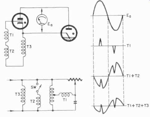
Fig. 727. Waveforms on the right result when in-phase and out -of -phase
voltages are used with peaking transformer to lire an ignitron very precisely.
The setting of R1 and R6 will determine the armature current. However, the armature current is not an accurate indication of speed, for the voltage (IR) drop in the armature will also depend on the load. The greater the load, the greater the current supplied by the control to try to maintain constant speed, and thus the greater the drop. This must be compensated for. In the circuit to the armature -control thyratrons there are two current transformer windings T2p. The secondary of this transformer is a center -tapped winding. T2s and rectifier VF (full wave) feed the divider R8, R9, R10, which has a voltage impressed on it proportional to the armature current. The arm on potentiometer R10 affects the voltage to the grid of VC, and the voltage on this arm is sub-stracted from the voltage supplied to this grid by R6.
Thus the compensation is applied to the armature control. The setting of R10 depends on the armature resistance, and is set only once for a particular motor.
The voltage across R9 is tapped off on R8 and applied to the grid of VE. Normally this grid is very much negative with respect to the cathode but, when the armature voltage rises high enough, this will change and VE will conduct. This lowers its anode voltage and the grid voltage of VD, again lowering the armature voltage. Thus VE, when fired, limits the current to the motor. This is simply a protective feature to avoid damaging the motor and the armature thyratrons, for example, when the load becomes excessive.
Control of the field current is similar but carried out by VDD, VEE and VCC, which take the place of the similarly designated tubes in the armature control.
R1, which sets the motor armature current, and R11, which sets the field current, are on a common shaft, allowing presetting of the motor control over the range of speed permitted by the motor design.
Fig. 728 is a simplified schematic-there are other parts to this control but, since they are not essential to understanding the control operation, they have been omitted. This control as shown is a constant -speed device. Not shown, but ordinarily present, are the motor contactors, reversing contactors, if any, and contactor control circuits, protective devices, etc. A similar control could be arranged to produce a variable speed in response to a demand from some source in the process, simply by varying the voltages on the points connected to the arms of R1 and R11 and the grid voltages on the control tubes.
Thyratron controls are used quite extensively in industry.
Thyratrons and ignitrons have been used for motor controls for over 30 years. Today there is a serious challenge to the unique position of the thyratron-the controlled semiconductor rectifier.
These are still so new that no extensive industrial examples are available. The basic function of the controlled rectifier was described in Section 2. Because this rectifier behaves like a thyratron, it too can be controlled by phase shift or by dc control voltages. The controlled rectifier however, has, so many other applications besides motor control, that a more detailed discussion will be found in Section 9, which deals with various static control systems.
---------
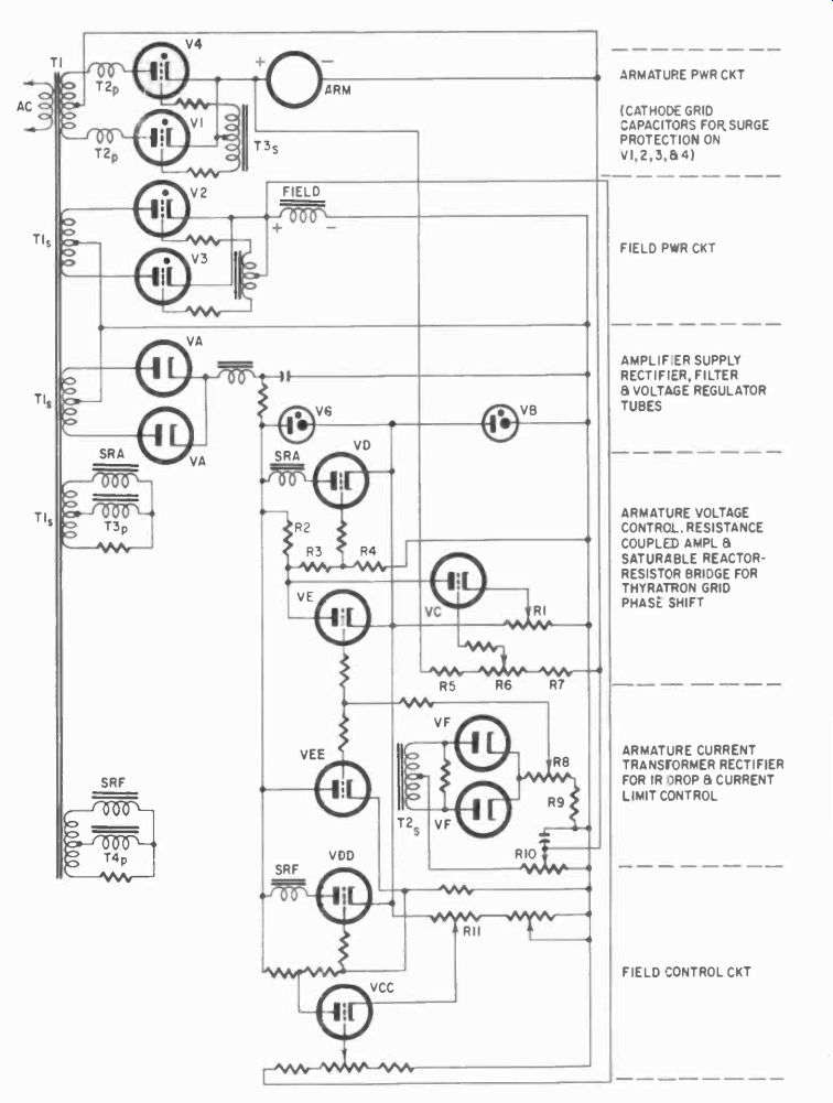
Fig. 728. Simplified schematic of G - E Thymotrol constant -speed motor
control. See text for explanation.
ARMATURE PWR CKT (CATHODE GRID CAPACITORS FOR SURGE PROTEC1ION ON V I, 2 , 3, & 4 ) FIELD PWR CKT AMPLIPER SUPPLY RECTIFIER, FILTER a VOLTAGE REGULATOR TUBES ARMATURE VOLTAGE CONTROL. RESISTANCE COUPLED AMPL & SATURABLE REACTOR - RESISTOR BRIDGE FOR THYRATRON GRID PHASE SHIFT ARMATURE CURRENT TRANSFORMER RECTIFIER FOR IR OROP B CURRENT LIMIT CONTROL FIELD CONTROL CKT
-------
Servos
A servo is another means of controlling machinery. The old ball type governor used on Watt's steam engine was a servo in a sense. As the engine speed decreased, the weights would tend to fall down from their orbit, and the motion would open a valve, called the governor valve, which then applied more steam to the engine, recovering speed in this way.
A room thermostat is another good basic example of a servo system.
What then are the elements of a servo system? First, there is the sensor, which tells what the actual conditions are (the thermostat bulb). Then there must be some kind of a standard or set to compare this with, to tell whether the condition is satisfactory.
On the thermostat this is the gadget you set for the desired temperature, and which is actually a normally closed switch that is opened by the thermostat bulb. Next comes the means to control the process.
In the thermostat, this would be the solenoid which operates the valve for gas or oil to the furnace. And then the process itself, which is the furnace, producing heat and changing actual conditions. When the thermostat determines that these correspond to the set condition, the furnace is no longer needed, temporarily, and will be cut off.
The most important part of the system is not too obvious in this example-the feedback loop. This in our case is the warm air produced by the furnace. Fig. 729 illustrates the principal components of a servo system. Often the feedback loop is more complicated, for the sensor may work in a mode different from the process. For example, in the case of a motor rotating a machine part, the signal which must he returned to the sensor is an electrical one (unless we use mechanical linkage, as in the governor). In some way, then, the position of the machine part must be translated into an electrical signal. This is the role of the translator (transducer), which can be a potentiometer with a dc voltage on it, but which often gets rather involved.
A typical industrial servo system could be the control of a motor through a tachometer generator. If, in the Thymotrol system discussed earlier, we provide the control grids of the tubes controlling the thyratrons with a dc signal proportional to the speed of the motor, we have made a typical servo system out of the control.
Note that we keep saying a servo system. The lone word servo may mean something else. If a switch is used to control a small motor remotely, to open a valve, then the motor is a servo motor even without feedback. The system is a servo system in a sense but, because it has no feedback, it is called an "open -loop system." This misnomer is simply a convenience, used by engineers in discussing control systems-an open loop is no longer a loop.
Servo systems can take many forms-vacuum tubes and thyratrons, controlled rectifiers, magnetic amplifiers, saturable reactors, etc. All kinds of transducers are used to generate the feedback signal, including mechanical linkages or some sensor appropriate to the process. For example, the magnetically read flowmeter mentioned in Section 6 could very well be used as the transducer in a system to control the flow of a liquid. Integrating the pulses from the flowmeter would give a voltage signal for control.
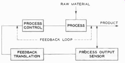
Fig. 729. Block diagram shows principal components of a servo system.
Servo systems will crop up again when we discuss industrial recorders in Section 10, for many of these are prime examples of servo systems used to control the recording pens. In such follow up systems the input to the system is operated by the output lo follow some condition. For example, when you look at any moving object, you will try to keep your eyes focused on it. This requires turning the head. The signals to your brain for turning the head are obtained from the eyes. This is a follow-up system. If we shine a light beam on two photocells and if we arrange their circuit so that the output will tend to equalize the light on the two cells by rotating or moving them in some way, then, when we move the light, the cells will tend to "follow" this light. Circuits for comparison of photoelectric-cell output such as we showed earlier in the Section could be used for this.
A follow-up system need not necessarily use photoelectric cells although it often does. It can use mechanical motion, pressure or even a gyro such as the automatic pilot on planes and boats, and need not be physically linked to the actual controlling element.
Summary
We have tried to give you a brief but as wide as possible a look at industrial controls. Many circuits can be made with relays, even complicated counting circuits and very complex control systems.
However, modern industrial practice is getting away from mechanical control devices, for obvious reasons, and are substituting more durable and reliable static controls as discussed in the next two Sections.
Once many industrial engineers had the attitude that "if it can be done mechanically, don't do it electrically." This was understandable when he had to deal with relays only. Next came the trend of "if you can do it with relays, don't use vacuum tubes," and this too persisted for a time, based on the early lack of reliability in the vacuum tube. Now we have a different situation which promises greater reliability and durability through static control.