AMAZON multi-meters discounts AMAZON oscilloscope discounts
MOST of the industrial controls discussed thus far have utilized electron tubes. In recent years transistors have also been used in industrial electronic controls to an increasing extent as their reliability has improved. The situation in regard to transistors is somewhat similar to that which existed some years ago when electron tubes were first introduced.
There is a natural reluctance on the part of industry to switch to something entirely new and often untried, due to the prohibitive costs of production-line failures. For example, failure of an electronic thickness gage on a rolling mill would mean that in a span of a few minutes many tons of sheet steel would be produced which were off standard and would have to be rejected. A more serious example would be the failure of an electronic flaw detector to spot a flaw in a steel beam designed to be the main supporting member of a large bridge. We can leave it to your imagination to visualize the cost of such failures.
Despite increasing applications of transistors in industrial controls, electron tubes will continue to play a major role due to the availability of reliable tubes either specially selected from a production batch, or with extra supporting elements. Also, the new ceramic tubes developed for high temperature requirements in space technology have the kind of ruggedness and reliability which will tend to make them desirable in industrial circuits.
However, mechanically-operated relays and switches do present a serious maintenance problem, and for this reason very serious efforts have been made to replace them with non-moving or static switching devices. These operate on magnetic principles but have no moving parts except for the final output unit (a relay, contactor or circuit breaker) which controls the machinery.
Principles of magnetic amplifiers
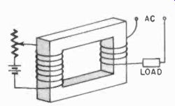
Fig. 801. Basic saturable reactor.
The magnetic amplifier originally stemmed from a saturable reactor (Fig. 801). In this case, the core, made from a material which is easily saturated, is magnetized by a control winding, while the load current passes through a heavier winding consisting of a few turns. When the core is not magnetized, the load current must provide the field for the coil on each half-cycle, which takes a certain amount of energy, and the core and coil have a consider able inductive impedance to the current because of this. If the core is now magnetized with dc, one half of the cycle need not build up the field, and the apparent inductive reactance will be considerably less. Thus by controlling the direct current in the control winding, we can, in this manner, control the alternating current in the load winding.
One application of saturable reactors is for lighting control, particularly for dimming fluorescent lamps, where resistor dimming is impractical. But for electronic control, a saturable reactor would be a rather impractical device because the field created by the load coil would reflect in the primary, and the device would act as a step-up transformer and would thus create rather high voltages in the control winding.
Therefore, in designing a magnetic amplifier, the core is constructed as shown in Fig. 802 where the magnetic fields of the two load coils on the two outside legs of the core cancel each other in the center leg. With the control winding on the center leg of this core, it is then possible to saturate the entire core, but in this case the control winding will no longer be affected by the load windings. This is the basic form of the magnetic amplifier, in which, with a small dc control current, it is possible to control relatively large amounts of ac.
If the core were built from ordinary magnetic materials, the device would not be very efficient, because such material is not easily saturated. But if the material used has a very steep B-H curve (B - flux density; H - magnetizing force - Fig. 803), then we obtain a very high amplification, analogous to a vacuum tube with very high transconductance.
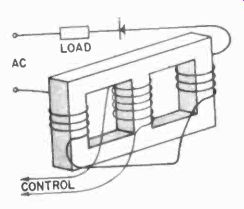
Fig. 802. Basic magnetic amplifier. Ac fields cancel in central core section.
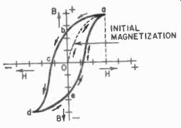
Fig. 803. Iron -core magnetization curve.
This basic magnetic amplifier has been represented symbolically in Fig. 804-a. With an ac load, we would, however, have control only during the half-cycle in which the load and the control currents work together toward saturation; during the other half -cycle we would have virtually no control But, if we insert two rectifiers into the load circuit, we will always have the load and the control currents working together (Fig. 804-b). For even greater efficiency, a full -wave bridge rectifier may be used (Fig. 804-c) .
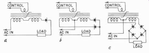
Fig. 804. Basic magnetic -amplifier circuits with half-wave (a), full-wave
(b), and bridge rectifier (c) circuits to provide dc.
Feedback improves the performance of a magnetic amplifier just as it does vacuum -tube devices. In this case we are striving for more gain, and therefore, positive feedback is used. Since we are operating with dc, we need not concern ourselves with such problems as oscillation. Fig. 805 shows a magnetic amplifier with feed back; its basic function is self-explanatory. As we increase the control current, we increase the current in the secondary or load winding and the current in the feedback winding, which in turn aids the control winding.
Fig. 805 is designated as a shunt feedback system since the feedback winding is in parallel with the load. With a different kind of winding (fewer turns of heavy wire), series feedback may be provided in the circuit in series with the load (Fig. 806). Gains up to 1,000,000 can be achieved in this way.
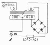
Fig. 805. Bridge -rectifier magnetic amplifier with shunt feedback and
ac load.
Further refinements can be had by adding circuits which control the winding that saturates the core. These can be vacuum tubes, thyratrons or transistors. If it becomes necessary to match unusual control signals to this dc control winding, such as signals from very high impedance sources, a cathode-follower circuit may be used for matching purposes. Or some kind of balanced circuit in which the control current is applied to two magnetic amplifiers in accordance with the received signal, which could be either a rising or positive signal, or a falling or negative signal. To control the magnetic amplifiers properly in such a circuit, with the balance point at zero, some form of bridge circuit must be used with vacuum tubes or thyratrons for the other two legs of the bridge, since the current through them is readily controlled.
Magnetic amplifiers have been used to amplify audio signals, using a high-frequency carrier (Fig. 807), but these devices are mostly laboratory oddities. In audio circuits, we seldom need the power levels of which magnetic amplifiers are capable, nor do we need their extremely high reliability.
However, magnetic amplifiers are used extensively in direct control of motors. Complete servo systems using only magnetic amplifiers are now commercially available, and they have a definite advantage where extreme shock and vibration are to be expected.
There is very little in a magnetic amplifier that can be damaged by extremes of acceleration.
However, magnetic amplifiers have certain disadvantages that have restricted their use. They are, first of all, much slower acting than vacuum tubes and are limited in frequency although ( Section 5) special ferrites will function satisfactorily up to 10 mhz. But, these would not be directly applicable for control in industry where 60 cycles is normally used.
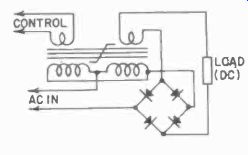
Fig. 806. Bridge-rectifier magnetic amplifier with series feedback and
dc load.
In this case, the initial cost of magnetic amplifiers and their bulk would not be competitive with electron-tube equipment.
Many devices do utilize magnetic amplifiers in their control functions, but the eventual use of magnetic amplifiers will not be so much in single, isolated units as it will be in coordinated complex control systems. Therefore we will discuss one such system which can carry out a great many control functions. We have already considered ( Section 5) flip-flops built from ferromagnetic devices and derived from magnetic amplifiers, as well as ferroresonant devices. However, these were high-speed units, with ferrite cores, using 1-mhz carrier currents, and not the 60-cycle low-frequency magnetic amplifiers we are presently discussing. Using the latter, we can build what are known as logic circuits, which we shall discuss next as an introduction to their use in an integrated control system.
Logic
Although there are many ways of controlling motors with analog type devices ( Section 7), the majority of machinery controls are digital in nature. Think of the literally millions of motors controlled by simple on-off switches, which are the simplest digital device.
Most large computers operate on a digital system. Even the most complex machinery controls can be reduced to a small group of simple digital operations. These operations have been labeled logic functions. The term logic as used here is a term borrowed from a special kind of algebra which is suited to handling digital data, namely Boolean algebra, which calculates with the kind of information discussed briefly in Section 5.
Logic can be considered as a series of statements or conditions which are mutually exclusive or which are necessary to each other for fulfillment. Thus, if you want to drive a car, you must first
know how and you must have the key to the car. If you want to buy a car, you must have either the cash or the equivalent credit.
These are two of the basic logic functions, and we call them AND, and OR gates. When a negative condition is required from either one, we get the NOT AND, and the NOR gates. The third important function to logic is the MEMORY. With the MEMORY, AND, OR and NOT gates we can delineate any complex set of conditions about anything we wish, so long as the conditions are clear-cut. Ambiguous conditions would simply be unclassifiable in our logic machinery.
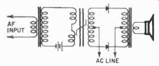
Fig. 807. Magnetic amplifier has been used to amplify audio frequencies.
Unless a supersonic ac source is used, the carrier is heard.
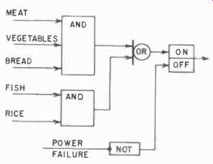
Fig. 808. The basic idea of logic operation is illustrated here.
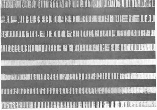
Fig. 809. Information stored on magnetic tape ran be made visible with
fine iron powder.
A simple example may help clarify this. In Fig. 808 the basic conditions, meat, vegetables and bread or fish and rice, both would make a meal, provided there isn't a power failure. The AND functions combine the necessary ingredients, the OR function decides between the two, and the MEMORY remembers that either will be inedible without being cooked, so the NOT function prevents the output of a meal if a power failure prevents the cooking step.
Basic memory circuits are familiar. The flip-flop in its various forms is the best known. The Encyclopedia Britannica could be set down in the form of properly coded flip-flops, which could then be read by noting the state of each flip-flop. However, even in the encyclopedia not all the information can possibly be used to advantage at one time in one place; thus, only a small portion of the memory need be accessible at any one instant. This allows memory functions to be sequentially stored, so long as it is possible to find any part needed, when it is needed. Magnetic tape and punched paper tape can therefore he used far more economically than flip-flops for memories. Fig. 809 shows a section of magnetic tape in which a number of tracks with stored information in binary form has been made visible with the aid of a fine iron powder.
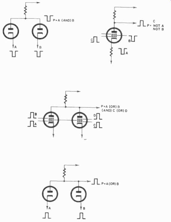
Fig. 810. Gates for and, and, or functions can be made with either diodes
or multi-grid tubes.
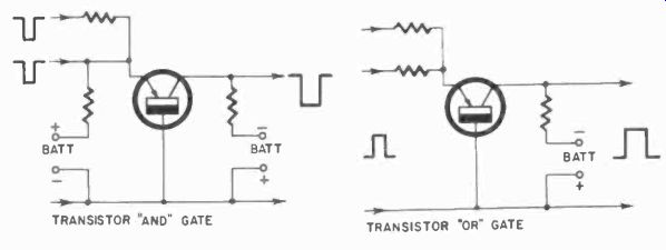
Fig. 811. Transistors are preferred for most computer applications. Their
use reduces the need for cooling equipment as well as making a more compact
device.
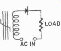
Fig. 812 (left). Hypernik core with winding, rectifier and applied ac
can be self-saturating.
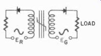
Fig. 813 (right). Adding a second or reset winding was done by Ramey.
Radically new circuits are not required for AND, and OR gates.
Fig. 810 shows some of the gates used for these functions, with the functions alongside them. The same kind of functions can be carried out by transistor circuits as shown in Fig. 811. Logic circuits can also be of the magnetic-amplifier type such as those developed by Ramey and manufactured by Westinghouse. In the form of a coordinated, complex control system it can he used to control any number of large machine operations or can even be built into a computer for certain applications. We shall discuss this system, marketed under the name CYPAK, as an example of a complex coordinated machine control system although there are, of course, other ways and systems of doing the same job.
Obviously, an industrial control system using magnetic amplifier principles, with the ruggedness, reliability and durability associated with this type of design, will have decided advantages.
A typical B -H magnetization curve has already been shown for high-quality core material used in magnetic amplifiers (Fig. 803). The Ramey units use a high -quality core material named Hipernik, which has an even steeper magnetization curve. This means that the material is rapidly saturated-so rapidly that, in the unit in Fig. 812, an applied ac of the proper value will make this unit self-saturating in much less than half a cycle of 60-cycle ac. When such a core is saturated, there is no reason for it to lose its magnetism, unless there is a decrease or reversal of current. If we were to break the current at- the high point of the ac cycle, the core would remain saturated for some time. If a second coil is now wound on the same core (Fig. 813) and an ac voltage is applied to it 180° out -of -phase with the first one, the core never gets a chance to saturate, and no current will flow in the load. Fig. 814-a is the normal output of one winding; at (b) a direct current has been applied to the other winding, which Ramey called the "reset" winding, and no output is available. The core may vary in its magnetism, but it will never reverse, and hence never produce an output in the load.
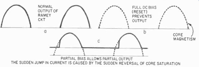
Fig. 814. Output currents from Hamel' unit with dc reset. PARTIAL BIAS
ALLOWS PARTIAL OUTPUT; THE SUDDEN JUMP IN CURRENT IS CAUSED BY THE SUDDEN
REVERSAL OF CORE SATURATION
If we have only a small current in the reset winding, we would have the case of Fig. 814-c. The core does reverse magnetism for part of the cycle, and some output is transmitted to the load, depending on how much dc passes through the reset winding. If we magnetize the core with a half-cycle of ac in the reset winding, it would, for one cycle, be the same as if we had dc in it. The core would have no reason to lose its magnetism and consequently most of the load or "gating" cycle would be taken up with reversing the core magnetism, with the result that there would again be no output. This is the basis of the Ramey switching unit. There is a half -cycle delay: - if the reset is prevented, there will be a response from the gate a half-cycle later.
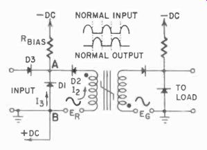
Fig. 815. Ramey unit with dc bias, windings and nave forms indicated.
To match this unit to other similar units several conditions must be met. First, the reset winding must have a low impedance in order to assure positive reset. But to avoid loading the previous stage, a high impedance input is necessary. Therefore, the unit is equipped with rectifiers and a dc bias source (Fig. 815). The bias current in the reset winding flows continuously, and, of course, to balance conditions in the gating winding, a bias is also required in this circuit (see Fig. 816). When an input signal is applied, the bias current in D1 is, in effect, cancelled and reset can not take place. Consequently, the unit will produce an output on the next half-cycle of the gate.
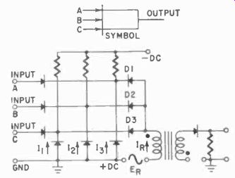
Fig. 816. Basic Ramey and circuit and symbol. Relay equivalent shows all
inputs must be present for output.
This is the basic Ramey switching unit. From this, various other logic units can be built by adding input circuits, etc., to obtain the desired function. Thus, in Fig. 816 we have added in effect, three diodes. Of course, each one must be blocked by an input signal or the reset current will flow. Thus the unit becomes an AND unit, and all three inputs must be present to obtain an output. A similar circuit can be designed with a different number of inputs, so long as each bias path is blocked.
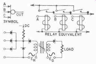
Fig. 817. Basic Ramey or circuit with the relay equivalent and symbol.
If input rectifiers are added, but only one bias rectifier (Fig. 817), any one of these inputs could block the bias rectifier current, and give us an OR unit. Again, the number of inputs is variable--there could be two, three (as shown) or more.
It is easier to make a unit that always gives an output except when a signal is present. All that has to be done is let the input signal be the reset current. The NOT unit in Fig. 818 is quite simple.
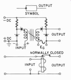
Fig. 818. Ramey not circuit with symbol and relay equivalent. As in the
relay circuit, if an input is present, there is no output.
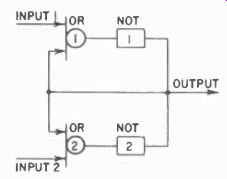
Fig. 819. The principle of the memory unit.
From two NOT and two OR units we can build a basic memory or storage unit. (Figs. 819 and 820). If NOT unit 1 produces a signal and this signal is fed back to NOT unit 2, through OR circuit 2, NOT unit 2 will not produce an output in the next half cycle. Each half-cycle NOT 1 will provide the reset for NOT 2 in this way.
An input at 1 will reset NOT 1 through OR 1. The reset of NOT 2 is then blocked a half -cycle later. Thus NOT 2 will start producing an output, which is then able to reset NOT 1's core, resulting in a changed stable state. A signal at input 2 can reverse the setup. This, then, forms a memory unit and, since nothing will happen to this setting unless there is an input signal, this kind of memory can be read repeatedly without losing its data. Fig. 820 shows the complete circuit. Only when power is lost will the stored data also be lost. However, there are units now which recover in the proper setting when the power comes on again.
Time delays are important ingredients of controls. With the Ramey circuits, we can also introduce a time delay as shown in Fig. 821 where C1, C2, RI, R2, R3, R4 and D1I and D2 have been added to a memory unit. The time constant of C1 is small compared to C2. As we supply an input signal (we assume that unit 1 is saturated and supplying an output), each half -cycle will build some charge in C1. How much of that charge is left on the next half -cycle depends partly on the setting of R2. The input to unit 1 (at A) is clamped at a voltage level by R3, R4 and D2.
Each increment of voltage charge on C1 will be too small to reset the unit but, because of D1, these increments will add up in C2 until enough voltage has been built up to provide the reset current.
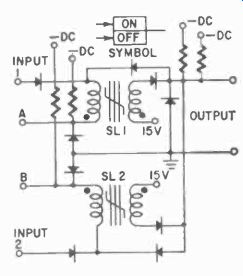
Fig. 820. This memory is made with two combination or and not units. See
text.
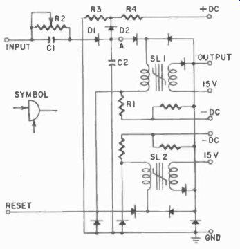
Fig.
821.Time-delay circuit made from Ramey units. Varying C2 and R2 will change
timing.
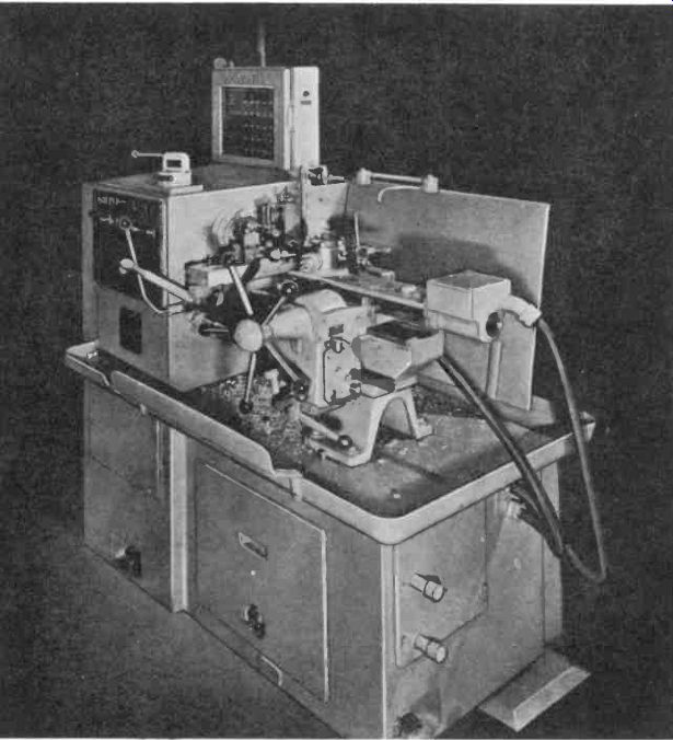
Fig. 822. This turret lathe has sequential operation control with a Cypak
system.
As long as the input continues, without this clamping action C2 would continue to charge and would require a higher voltage capacitor. Also, it is possible to discharge C2 faster if the voltage on it is lower. Functionally, the clamp D2, R3 and R4 would not be absolutely necessary. Discharge of C2 takes place when a signal is applied to the "reset" unit, and clamped at zero by D3 (otherwise it would go negative from the reset input). If a simultaneous input is supplied at both terminals, then the time delay will be generated as soon as the reset input is blocked. Thus, since the circuit is initially in its "reset" state and producing no output, the output will commence as soon as C2 is charged - in other words, after the delay set by R2 - and it will stop only when a reset input is again applied.
It is easy to see how the operation of these memory units could be set with a group of toggle switches which would provide a definite sequence of operation, which, in turn, provides a sequence and nothing can he done until the previous cycles have been completed. This is, of course, nothing new in industrial controls, but usually this sort of thing has been handled with relays which are subject to wear, mechanically, and to contact failure, etc. With the nonmoving CYPAK or similar units, the system is dependable as long as there is power to operate. (Relays would also fail with power failure, of course) Fig. 823. Basic magnetic output amplifier circuit for Cypak system has extra windings to allow the two inputs to be circuited in series while the outputs are paralleled.
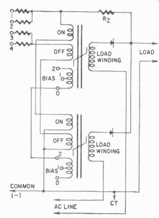
Fig. 829. Cypak control diagram and the relay equivalent. Do not confuse
the contacts with the electronic schematic symbol for capacitors.
Switching is also faster; few relays will perform a switching operation with the speed of a half-cycle. Also, apart from the dc bias supplies, the system operates on 60-cycle ac.
A typical control system using these CYPAK's is shown in Fig. 822. This setup controls the sequential operation of a turret lathe.
The basic Ramey unit can also be used as a preamplifier. If a preamplifier with more than one input is required, a two-input preamplifier is available which is very much like an AND circuit.
Several Ramey units may also be combined and used as output power amplifiers to operate relays.
Fig. 823 shows the basic amplifier. It consists of two one -input "AND" circuits with their outputs combined (the quotation marks are prompted by the fact that one input would not really make it an AND circuit - it merely looks like one). This amplifier produces a full -wave output, rather than the characteristic half-wave output, thus doubling the average power from the unit.
Specially designed units are used for greater outputs, up to 300 voltamperes. These are double -type magnetic amplifiers, and not strictly the Ramey units we had been discussing.
Circuits Let us see how these logic units can be used in circuits to replace relays or, to be more accurate, to replace relay functions with static switching functions.
Fig. 824, a partial schematic of a relay, is a typical configuration and might appear in almost any control diagram, just below it is the CYPAK equivalent. In Fig. 824 we see that coil CR will be energized when A, B and C are closed, when D is closed and when E is not opened. In CYPAK terms, this adds up to having a signal at either A or B and C, and also at E, but a signal from D must be present, regardless of whether the A signal or the B-C combination is available.
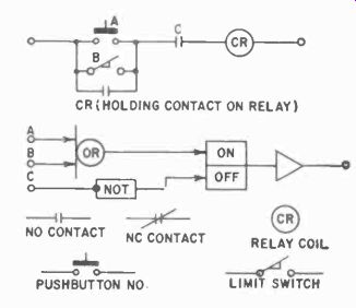
Fig. 825. The holding or latching circuitry of a Cypak motor control and
its relay equivalent. Schematic symbols are identified.
Fig. 825 includes starter button A, limit switch B and holding contact OR on coil CR. Thus if A or B is closed, and C is closed, CR can be energized. In terms of the CYPAK circuit, when a signal is present at A or B and there is a signal at C (producing NO output), coil CR will be energized so long as the memory is not reset. As soon as a signal is net received at C, the NOT circuit resets the memory. In other words, the coil will be de-energized, unless simultaneously a signal from A or B is received.
More complex, the circuit of Fig. 827 is a partial diagram of a hoist control. This portion deals with the hoist motion of the control.
First let us consider the meanings of the figures in the diagram.
For convenience, the symbols are repeated in the chart of Fig. 826, together with the output and action of the circuits. Note that all logic elements are numbered. The number identifies the location of the unit, and the service technician would have to refer to a wiring diagram to locate the unit. This is not shown here. Letters (in Fig. 826) indicate the module function; A, AND; N, NOT; PA, preamplifier; T, input transformer; E, OR; TD, time delay; and AA, additional input AND.
Note, for example, that module 11 (for typical module, see Fig. 828) contains both a pre -amplifier and an OR element, designated 11 PA and 11E, respectively. Memory circuits are separately numbered but, since they are made up from other logic elements, these are identified. Memory MI is actually composed of NOT 7N and NOT 8N. Power amplifiers are separately numbered, suffixed with the letter P. Potentiometers are separately numbered, suffixed "pot". The terminal numbers are those of the modules. These modules all fit into a prewired bus and can be inserted several ways, which is the reason for all the terminal numbers. In sheets describing the modules, the terminal designations are indicated. In our diagrams they were not shown.
The power supply terminals, which automatically make the right connections when the unit is plugged into the bus, are not numbered.
In Fig. 827 we are concerned with the up motion of the hoist.
The unit marked UP is the contactor which finally energizes the hoist motor. LS are limit switches, limiting the travel of the hook.
We cannot readily translate this diagram into a relay diagram because it is a partial diagram - we have no way of determining where the various signals come from. Thus we could show a time-delay relay in place of 4TD and a contact, which would represent the signal on line IS, but we would not know which relay this contact belongs to. In any case, in servicing a CYPAK system, complete service and troubleshooting instructions will usually be available, and it will be found that most CYPAK troubleshooting is very simple.
-------------

BASIC LOGIC ELEMENTS
OPERATION REQUIRES ALL INPUTS TO BE PRESENT CXJRING
0. PHASE IN ORDER FOR "C" PHASE OUTPUT TO APPEAR I/2 CYCLE DELAY S PRESENCE OF ANY ONE INPUT YIELDS AN OUTPUT IMMEDIATLY.
NO TIME DELAY PRESENCE OF 0 SIGNAL PREVENTS OUTPUT ON "C" PHASE "0"SIGNAL ABSENCE CO CAUSES SIGNAL TO APPEAR.
GIVES 1/2 CYCLE DELAY.
OUTPUT ASSUMES THE PHASE OF THE LAST INPUT SIGNAL THAT APPEARED ONE CYCLE DELAY COMPOSED OF TWO NOT ELEMENTS AND ONE RETENTIVE MEM ORY ELEMENT RETAINS EXISTING STATE THROUGH A POWER FAILURE.
OUTPUT ASSUMES THE PHASE OF THE LAST INPUT SIGNAL THAT APPEARED ONE CYCLE DELAY COMPOSED OF TWO NOT ELEMENTS EXTERNAL CIRCUITRY ARRANGED SO THAT UNIT SWITCHES OFF(C) ON POWER FAILURE USED IN CONJUNCTIONA WITH MEMORY TO PROVIDE DELAYED SWITCHing .
SWITCHING OF MEMORY OCCURS AT SOME PRE-SET TIME AFTER INPUT APPEARS ON TIME DELAY ELEMENT.
NOT PHASE SENSITIVE AMPLIFIES LOGIC SIGNALS TO A LEVEL WHEREBY THEY MAY ENERGIZE SMALL LA, 6 VOLT PILOT AMP,_A____OR POWER AMPLIFIER.
SAME AS THE HALF WAVE CONFIGURATION EXCEPT OUTPUT IS 12 V 0 C AND PROVVES 4 TIMES AS MUCH POWER. USED WITH AMPLIFIERS AND RELAYS PROVIDES ADDITIONAL NPUTS TO AND ELEMENTS PROVIDES VOLTAGE TRANSITION PROM 120 VAC, WHICH IS RELABLE VOLTAGE FOR PILOT DEVICES, TO LOW VOLTAGE CYPAK LEVEL AMPLIFIES LOW ENERGY CYPAKSIGNALS SO THAT THEY CAN ENERGIZE A GE LOAD SUCH AS A MOTOR STARTER
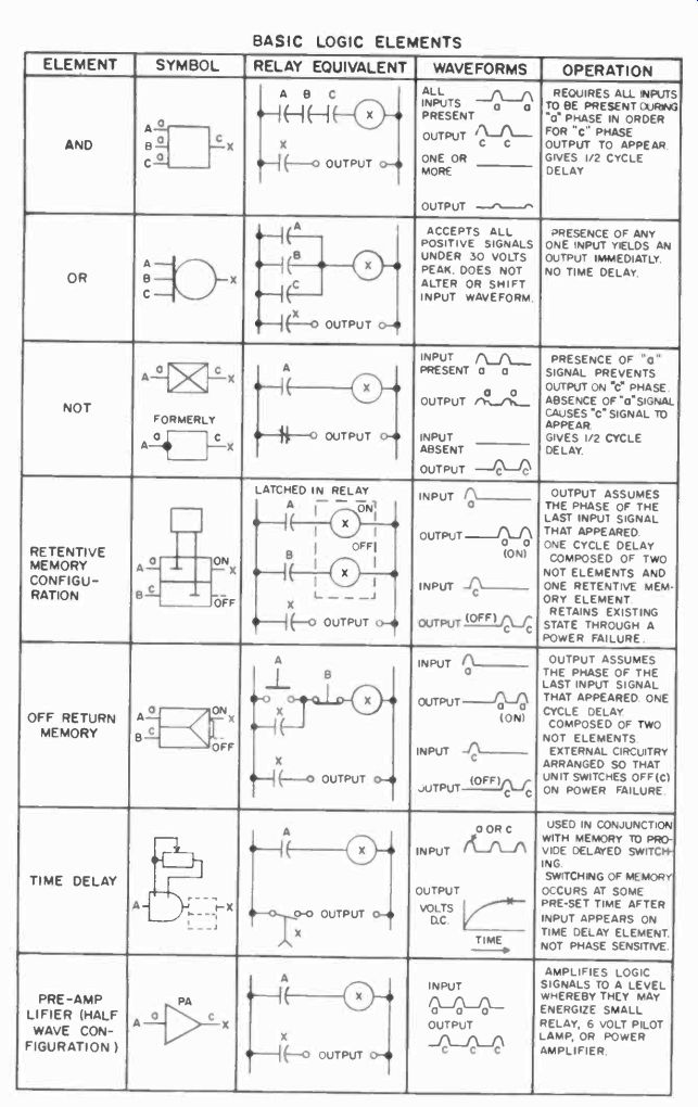
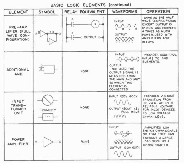

Fig. 826. Basic logic elements are shown related to their symbol, relay
equivalent and normal waveforms. Brief description of operation is included.
-------------
Servicing a CYPAK system
The reliability of CYPAK and similar systems is so high that a failure is a rare event. But several things should be remembered when servicing. For example, the output signal does not appear at the same time as the input, but one half-cycle later. Phase of the output and input is therefore of importance, and all the units in the chart of symbols have been marked with the conventional phase designations, (a) and (c). To reverse the phase of any one unit it is necessary only to reverse its position on the bus.
A phasing detector, (a phase -sensitive voltmeter) or a unit made up from two preamplifiers and an OR unit and two indicator lamps will also serve the purpose (Fig. 828). The green lamp will glow if the (c) phase output is measured, the red lamp for the (a) phase, and both if the signal is full-wave, as it would be from a power amplifier, for example. An oscilloscope with the sync circuit connected to the same power -line phase as the units will also detect phase. Normal peak value of a CYPAK output signal is about 21 volts. This registers on the dc meter as 6 volts. For full -wave signals you would read a higher voltage, of course, but not on a dc meter.
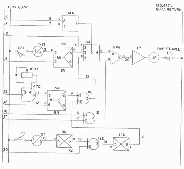
Fig. 827. Portion of a typical Cypak control diagram dealing with the
up motion of a hoist.
As in any troubleshooting, the first things to check are the avail ability of power and the operation of the power supply. Half-wave dc voltages of -23 volts should be available on the buses, and -45 for power amplifiers. The next step is to check the end item, which may be a contactor or a relay. Note that in our sample diagrams there was more than one way to energize such a circuit.
While working on a system, to insure that the machine will not accidently start, disconnect some lead, or fuse either to the machine proper or to the final output items of the control system. From our discussion of logic units and the chart (Fig. 826) you know what voltages must be present to make them operative, and the troubleshooting procedure then becomes one of finding the appropriate voltages or the absence of them, step by step, so that the faulty unit can be located and replaced. Nothing could be simpler after that-simply obtain a replacement and plug it in.
To service such a system effectively in a minimum of time, it is advisable to study any and all manuals which come with systems under your care until you are familiar with their operational sequences. They should be completely understood from a logical build-up of the units we have shown, and, if special units are used in the system, the manuals will explain their operation in detail.
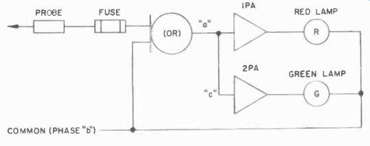
Fig. 828. Phase detector made from or unit and Iwo preamplifiers.
Other magnetic control systems
So far the discussion has been limited to the Westinghouse CYPAK system which is based on Ramey units, and which is presently being used to control many kinds of large industrial processes. But conventional magnetic amplifiers can do the same control job if we build logic units from them. To do this we must take advantage of the switching characteristics which all of them will exhibit with the application of proper signal, bias, feed back and power voltages. We can then switch these units between two states of saturation, as we choose, or between a state of saturation and non-saturation, again depending on the applied voltages.
General Electric builds two kinds of control systems, one based on conventional and the other on pulsed magnetic amplifiers. We will briefly discuss both systems.
Static system from conventional magnetic amplifiers Fig. 829 is the schematic diagram of a conventional magnetic amplifier arranged for logic service. Here we have two cores, each with load windings, and a set of bias and combined feedback and signal windings common to both cores. Note that a center tap is required on the supply, which then gives us full-wave output.
The on and off windings have obvious purposes. Note that the bias winding is also center -tapped so that we can apply zero, one unit or two units of bias as we need or choose. The bias opposes the effects of the signal windings.
The feedback in the winding will tend to aid the on winding.
Fig. 829. Switching unit made from conventional magnetic amplifier can
be used for logic functions.
It is fairly obvious how logic units can be built from these amplifiers. If we have two units of bias and require an on signal at terminals 1 and 2, we have a two -input AND unit. If we tie the two input terminals together and supply only one unit of bias, we simply have a switching unit. If we set the bias at one unit and supply separate signals for either 1 or 2, each of which is sufficient to turn on the unit, we have an OR unit. With zero bias, the feedback winding keeps the unit saturated even when the input signal is removed, and we can call this a memory unit which will remain "on" or "off" according to the last pulse signal. Similarly, we can manipulate the bias and the "off" windings to produce a NOT and an OR-NOT circuit, which is a unit turned off by either of two NOT pulses, one at 3 or one at 4. The OR-NOT unit, commonly designated as the NOR unit, may be used as the basic element of an entire control system. We have discussed to some extent how these logic units can be used to form a control system. With this type of conventional magnetic amplifier unit, a relay or contactor may be used as the final element, if the sys- tern must function as a binary device. However, a magnetic amplifier can be designed that does not require a relay or a contactor and may be used for certain control functions directly.
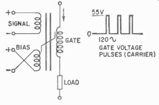
Fig. 830. Basic circuit of pulsed magnetic switch with waveform.
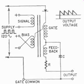
Fig. 831. Adding feedback makes the pulsed magnetic amplifier suitable
for logic functions.
Static control system using pulsed magnetic amplifiers
The other General Electric system uses magnetic amplifiers in a somewhat different way. (Fig. 830). This basic unit has three windings: a gate winding, which we have been calling the load winding; a bias winding and a signal winding. Note that, in the positive saturation, and load current will flow. The signal has, in effect, nullified the bias current. Remember that we are again dealing with a rectangular magnetization curve, which indicates that after a certain level of current is reached, the core will magnetize very rapidly.
If we add a feedback winding (Fig. 831), a rectifier and a capacitor, We have a true switching unit. As the pulses arrive, the capacitor will charge. When no pulses are present (between pulses), the rectifier will prevent the discharge of the capacitor in anything but the feedback winding, which keeps the core saturated between pulses. We can make the feedback strong enough (or the bias weak enough) to keep the core magnetized with no signal at the input.
To turn the unit off we will need a strong negative signal. This we can supply by reversing the connections of the off winding.
Essentially, this is all there is to simple logic units. For example, the NOT unit of Fig. 832 looks very much like the basic switching unit, except that the bias winding has been replaced with the NOT signal winding, and notice that it is also "reversed." Instead of the constant bias which opposes saturation, we now apply a NOT signal to prevent it.
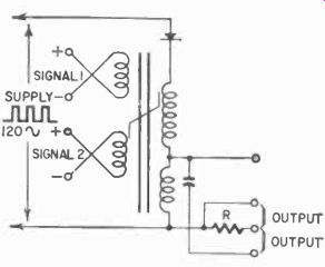
Fig. 832. Pulsed not circuit.
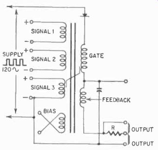
Fig. 833. Pulsed or circuit.
If we have several windings, each of which is sufficient to turn the unit on, we have an OR unit (Fig. 833). The core is not saturated until as lease one input is present, and then the bias effect is cancelled and an output is produced.
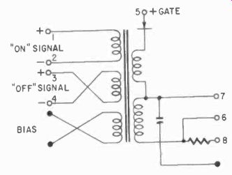
Fig. 834. Pulsed memory circuit.
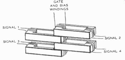
Fig. 835. Slacked cures for and unit have common gate and bias winding
hut separate signal windings.
The memory must include a bias winding, an overgrown feed back winding and an on and an off winding. Used as a switch, such a memory unit is not changed by being read. It simply conducts or does not conduct the signal from input to output (Fig. 834).
When provided with enough feedback (or little enough bias) to keep the unit saturated, a signal, once applied, leaves a condition that does not change even when the signal is removed, giving us a memory for the system.
The construction of AND units is a little more ingenious. Several cores must be stacked and given a common gate and bias winding but separate signal windings (Figs. 835 and 836). Any one of the cores is capable of blocking the gating current, and an input to all of the core signal windings is required to effect an output.
In a control setup, all the bias windings (those in a section of very large systems) are connected in series to provide a fail-safe system. Otherwise, failure of a bias would turn a unit on, and units operating out of sequence could have disastrous results. It is better to have the entire system shut down rather than take a chance on losing bias only. In series with each chain of bias windings, there is a relay coil to shut off all the power.
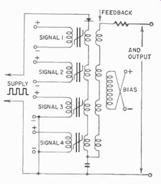
Fig. 836. Schematic of four input and units.
Power for the system is obtained from a supply using saturable reactors and rectifiers to form the pulses, which come out at the rate of 120 per second. The method will be shown in several steps.
Fig. 837 illustrates the first step. If we put a reactor in series with impedance Z, and this reactor saturates near the peak of the sine wave, the resultant voltage across A-B is as shown because the voltage drops sharply to zero when the core saturates.
If we put a second reactor which saturates even more easily in series with the first one, the voltage across it will rise with a very steep wavefront. (It has the same waveform as across Z in Fig. 837-a.) But since it also saturated, the decay will be sudden as before, and the result will be pulses with both a short rise time and a short decay time; in other words, sharp rectangular pulses.
Replacing the second reactor with a transformer and the Z with a bridge rectifier, we have the complete power supply as shown in Fig. 837-c, which also shows the bias windings in series. For the signals, we must include yet another dc supply, but this has no unusual features.
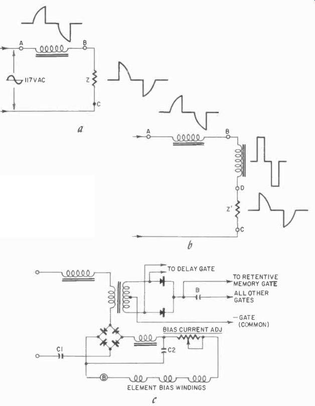
Fig. 837. Development of pulses in power supply circuit. See text.
Finally we come to an important control element, the delay unit (Fig. 838). Here we have two cores each with a link winding and a load winding. Gate pulses which drive the cores will alternate.
When a pulse drives core 1 toward saturation, the link winding causes a small negative saturation to be induced in core 2. When the gating pulse of core 2 arrives, it will negate this by driving the core a bit positive and, incidentally, will reduce the positive saturation of core 1 through the link winding and so on. The amount of each step will be determined by the setting of the potentiometer.
Eventually, a bit at a time, the cores will saturate and allow the load current to pass.
Fig. 838. Physical arrangement of pulsed delay unit is shown at (a) while
the schematic is given at (6).
Actually, we must have some way of making the cores pass the load current suddenly after the time delay, and not by bits and pieces at a time. How this is done is shown in Fig. 828-b. Bias, permanently applied, is opposed by the control input.
As the cores approach saturation, the control current increases, increasing the drop across resistor C. When this drop reaches the breakdown value of the zener diode, the bias current suddenly flows to common, and the sudden removal of the bias gives the cores their final "kick" toward saturation, thereby permitting the load current to pass through.
Fig. 839. Magnetic-amplifier flip-flop demodulator circuit is used to
obtain square output pulses at the counting rate.
The G-E systems are packaged in encapsulated units, that plug in, so that their servicing and troubleshooting problems are similar economically to those of the CYPAK, though technically different.
No phase differences need be reckoned with.
Although static control systems function differently, and their logic units are made up in different ways, have different input and output signals and different ways of connecting together etc., the principles of building systems from logic units do not change, since these are a matter of system concepts only which we shall discuss later.
Other types of magnetic-amplifier switching units Knowing the switching characteristics of magnetic amplifiers, we might ask if they could not also be used to build what is familiarly termed a flip-flop, one of the more common types of switching circuits. They can. Fig. 839, a magnetic amplifier flip-flop, shows two cores with appropriate gate (or load), signal and feedback windings. The latter also serve as bias windings as will be shown.
The rectifiers provide the dc voltages used to saturate the cores.
The power winding also generates some dc voltage in the rectifiers.
Fig. 840. Magnetic-amplifier servo system controls de motor.
With conventional flip-flops, we are accustomed to thinking in terms of conducting and cutoff states of the tubes. Keep in mind that, in magnetic amplifiers, the saturated state corresponds with the conducting and the non-saturated with the cutoff state. In the saturated state, however, the magnetic amplifier (unlike the cathode circuit in a tube flip-flop) will not generate a bias, since no voltage is induced on the winding, while in the cutoff state a very large voltage is induced on the bias winding.
Looking at Fig. 839, we see that the bias windings are in series with each other. Assume then, that core 1 is saturated, and this circuit conducting. Since no voltage is generated in bias winding 1, but a large voltage is in the bias winding on core 2, which aids the voltage generated by the power winding, core 1 will have a relatively large dc in its bias (feedback) winding, keeping the core saturated. If we apply a signal to the signal winding, this core will momentarily de-saturate a bit. This causes a voltage to be induced in the bias winding on 1, which will, after rectification, produce a dc in the bias winding on core 2, giving this core a bit of magnetization toward saturation. This in turn reduces the dc feedback fed to the bias winding on core 1, and so on, and we have the typical "runaway" or regeneration process as we know it from other kinds of flip-flops. Thus, with a strong enough signal in the signal winding, the units will change state. Inversely, the next pulse will give core I a bit of magnetization, reducing the dc bias it is now feeding the bias winding of core 2, and reducing the current keeping core 2 saturated. The units will again change state, a typical flip-flop action.
Fig. 841. Thyratron and magnetic -amplifier circuitry to control a split-phase
motor are quite similar.
In this kind of a flip-flop, we will not usually employ the core material used in magnetic amplifiers generally. To be of real value, the flip-flop must be much faster than we can make it with ordinary core steel, or even with the special high -permeability steels used in magnetic amplifiers. Instead, we use a ferrite, something which looks like the material in the loopstick, but has radical magnetic characteristics which yield even more sharply defined square -waves in the magnetization curve. Thus ferrites also have two states, saturated (in either direction) and unsaturated.
For the flip-flop shown in Fig. 837, we need not concern our selves with the negatively-saturated state, since we use only positive -going pulses for the power supply and there is no way negative saturation can be achieved.
Other magnetic amplifier applications
Although we have been discussing mostly digital control systems and have consequently stressed the switching characteristics of the magnetic amplifier and its various derivatives, there is also hardly any limit to the analog applications of magnetic amplifiers.
Some of these were indicated in the beginning of the Section the magnetic audio amplifier, as an example. Fig. 840 is a more realistic industrial application, and one which represents a whole class of applications, the control of motors by magnetic amplifiers.
The function of this equipment is apparent from the diagram.
There area host of such applications in industry, all more or less related to this kind of a control job. Fig. 841, for example, compares a control using thyratrons and one using magnetic amplifiers for the same job. Here the polarity of the input signal in the saturable input reactor determines which half of the amplifier will allow its thyratron to function first, or its magnetic amplifier half to saturate first, and thus determines the phase relation of the two windings in the split -phase motor. This, in turn, deter mines the direction of rotation of the motor. In both cases there is no speed control, merely directional control.
Summary
Development of magnetic amplifiers has not stood still. One type has recently been invented which can show a variable gr,, just as does the variable-mu vacuum tube. But this is so new that industrial applications are still, at best, theoretical.
Magnetic amplifiers are by no means the only static type of control. Industry uses many types of control processes, and the way these processes progress in time has a great deal to do with the types of components used in them. Thus, the binary devices we have been discussing, magnetic amplifiers, are primarily used in repetitive processes, although they really have no inherent limitations that prevent their use in programmed systems. However, such systems rarely have need of logic elements, and the magnetic amplifiers in this case are amplifying and switching devices.