AMAZON multi-meters discounts AMAZON oscilloscope discounts
TRANSISTORS can be used for logic gates, but they are more likely to be found in a complete coordinated system, such as the NOR system marketed by Westinghouse, so called because it is based on the NOR circuit, a simple logic circuit with but few components.
To build logic functions we must have some kind of switch with two stable states, conducting and nonconducting. The transistor can be used in this way. The developers of the NOR system chose the grounded -emitter as the best circuit configuration for its reliability, economy and the possible variation of transistor characteristics.
Fig. 901 shows the basic common-emitter switch circuit. The base is provided with reverse biasing to get complete cutoff, within limits of the transistor quality. The switch of Fig. 901 is the basis for the logic circuit of Fig. 902. This circuit will have an output as long as the transistor is biased to its nonconducting state. In other words, as long as we have an input on neither 1 NOR 2.
This is how the circuit derives its name.
The circuit is shown with two inputs, and, for convenience in making connections, with two outputs. Actually, as many as 10 can be included. When, rarely, more than 10 are needed, we must include some means of isolating the various inputs and outputs more efficiently than through the resistor. We can, of course, use only a single input, and then we have what we label a NOT unit, since the unit will provide no output, due to the shorting effect of the transistor.
From this basic NOR we can build all the units (Fig. 903) needed for the logic functions of a control system. In fact, they can even be made into a computer--Westinghouse has built one called the NORDIC.
Fig. 903-a shows the NOT circuit symbol and Fig. 903-b the NOR circuit with two inputs. An OR unit (Fig. 903-c) can be made from a two -input NOR followed by a single -input NOT. Its action is simple to understand. So long as we have no output from the NOR, with a signal input on either A or B, we will not have a signal at the NOT, and consequently an output from it.
Fig. 903-d shows an AND circuit built from two NOT's and a NOR. Either NOT circuit will prevent an output from the NOR, so long as we have one NOT without a signal. It takes a signal on both NOT's to get one from the NOR. Thus we get the AND function. We can add as many inputs to the NOR as we wish and, by adding more NOT's, we can make an AND circuit for more than two items.
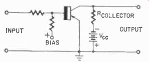
Fig. 901. Basic common-emitter transistor switch circuit.
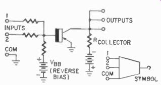
Fig. 902. Basic nor logic circuit with two inputs and three outputs.
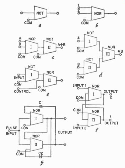
Fig. 903. Block diagrams shows how basic not unit (a) with a second input
becomes a nor unit (b). An or unit (c) is made from one of each. An and
unit is at (d). inhibit gate at (e), memory flip-flop at (f) and time -delay
unit at (g).
Fig. 903-e is another kind of circuit, an inhibiting gate, made from a NOT and a NOR circuit. It looks like half an AND.
So long as we have a signal on the input but nothing on "control," we will have an output from the NOR. But as soon as we put a signal on the control, the NOR will saturate, and we get no signal. NOR Remove the control, and we have an output again. This gate circuit is a very useful one for isolating, connecting, disconnecting and control, used in conjunction with other NOR units.
Fig. 903-f shows a NOR circuit flip-flop, which can function as the memory unit. The operation of the flip-flop can be easily understood if we start with the power off and both transistors nonconducting. When we turn on the power, both transistors will give an output. One will be very slightly faster and will saturate cutting off the output from the other one. Suppose I is cut off and II is now conducting. The output from II keeps I cut off until we apply a signal at 2 to make II nonconducting. This immediately stops the output from II, and I becomes saturated.
The flip-flop has changed state. A signal at 1 will again reverse the condition, and so on; each pulse, provided it arrives alternately on 1 and 2, will change the state of the memory unit.
Time delay, an important function in control systems using logic, is also used in the NOR system (Fig. 903-g). Here it consists of a two -input NOR, a three-input NOR and two capacitors.
Normally, unit I is cut off, producing an output, which keeps II saturated with no output. If we apply a short pulse to the common input, both transistors will momentarily he in the conducting state. With the pulse removed, II tends to become "open,- but capacitor C2 will have a charge stored on it, which will keep II saturated charge on C1 will du the same for I. until this charge has leaked off. During this time there will be no output.
But as soon as C1 is discharged, I again becomes nonconducting, and the output reappears. The time constant is determined by the size of C1 and the circuit resistances. But C2 will have to be at least as large, since it must keep II saturated until I is again in the nonconducting state, producing an output and holding II con ducting with it.
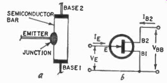
Fig. 904. The symbol for the uni-juncion transistor and its internal construction.
The NOR is an economical system. It uses only one kind of circuit configuration in the unit, one simple building block, the ideal situation for mass production.
Other static switches
Besides the NOR system, there are many static kinds of switches which could at some time be developed into industrial control systems. For some, the basic logic units have been designed as well as many other circuit configurations. Many kinds are already used in computers for military uses. There are some potentially useful industrial circuits among them. Other devices are so new and some so expensive to manufacture that they have not yet been applied to industrial electronics.
One of these promising devices is the Unijunction transistor (Fig. 904). A silicon bar is mounted on a ceramic wafer with two gold "base" contacts. This gives the transistor two bases. An emitter junction is applied to the bar, usually closer to one base than the other. With no emitter voltage applied, the silicon bar will act as a resistor. But the field inside the bar will create an emitter-junction voltage which, in effect, reverse-biases the emitter.
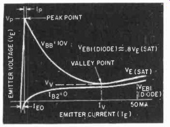
Fig. 905. Unijunction transistor characteristic curve with valley point
indicated.
Curve reversal makes it usable as a switch.

Fig. 906. Basic Unijunction transistor circuit is bistable.
Emitter characteristic curve is typical.
If we apply a voltage smaller than this emitter-junction voltage from an external supply, the junction will remain reverse -biased.
But if we apply a larger voltage, holes will be injected into the bar, and these will drift to base 1. They will increase the conductivity of the bar between the emitter and base 1. This will increase the emitter -to -base -1 current but, at the same time, be cause of the increased conductivity, will decrease the emitter-junction voltage-in other words, a negative resistance effect.
We can make use of this characteristic (Fig. 905), since it allows us to exploit the "switching" nature of the device.
The simple flip-flop of Fig. 906 needs a positive trigger at X to change state, or a negative trigger at Y. A negative trigger at X will again make the circuit change state.
Obviously, the Unijunction transistor will make an excellent switch for logic design, but as yet it is more expensive than the transistor now used for the purpose.
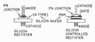
Fig. 907. Silicon controlled rectifier construction is shown and compared
to the silicon rectifier.
A static switch which started out to be something else is the silicon -controlled rectifier (Fig. 907). It is analogous, in a way, to the thyratron in that we can trigger it with a signal, but we must lower the supply or bypass the rectifier to shut it down.
Different from the thyratron, we need a current rather than a voltage signal. Note in the drawing that the standard silicon rectifier has a single n-type wafer to form the junction, while the controlled rectifier has an n-type layer with two p-layers diffused onto it.
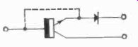
Fig. 908. The transistor-diode circuit is used as an analogy to the silicon
con trolled rectifier.
The principle of operation can perhaps best -be understood by the analogy to a diode and transistor. (Fig. 908). Here the transistor is in the nonconducting state, and a signal to the base will make it conduct. Then the current through it will develop sufficient voltage at the diode to break down the diode, and at the same time generate sufficient voltage to keep the transistor con ducting. The only way to stop the current is to reduce the supply, so that once again the diode will be reverse-biased. Note that the breakdown comes as the result of the signal applied to the base, which reduces the "resistance" presented by the transistor, allowing the full supply voltage on the diode. The signal itself was too feeble to initiate the breakdown directly. Consequently, the signal would also he insufficient to turn it off.
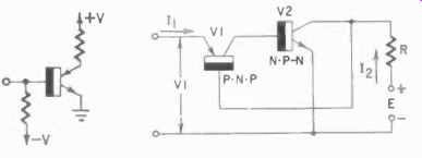
Fig. 909. Basic trigistor circuit replaces two transistors in flip-flop
circuit.
Many circuits, besides straight rectifying circuits, have been de signed based on the controlled rectifier. Even flip-flops can be made. But in general, the controlled rectifier will find its place in industry primarily as a substitute for the thyratron, and as a final element in control systems, possibly replacing relays and contactors in the last step of other control systems.
Another p -n -p -n device is the trigistor. Although it uses the same sequence of semiconductor layers, it differs from the con trolled rectifier in that it can be turned on and off by the trigger signal, thus making it an ideal switch for bi-stable circuits.
In Fig. 909, a p -n -p and an n -p -n transistor are so connected that each collector drives the base of the other. The gain of this circuit is the product of the gains of the two transistors. So long as these are both less than one, the unit is quiescent. But if we apply a trigger to the base of the one transistor, this transistor will conduct, increasing its gain and firing the other one, also in creasing its gain. Then the two are conducting and have reached the other stable state, conducting. A signal to the base will again reduce the gain of the one transistor, and degeneration takes place, turning the trigistor off. Obviously a very simple bi-stable device, the trigistor has been designed into counter and logic circuits, primarily for computer applications.
A static switch which is of interest, although also a long way from being applied in industry, is the cryostat. A tantalum wire, when super-cooled (4.2 . K), will change its conductivity from virtually zero to a few milliohms per inch, when we apply a small change of magnetic field. A few milliohms seems like very little to build logic circuits with, but consider this in the light of relative resistance change, which becomes quite a lot when we consider that the zero is just about that. Cryostats consist of 1 inch of tantalum wire, 9 mils in diameter, with about 250 turns of Niobium wire around it (Fig. 910-a). Niobium has a different point at which it changes from superconductive to a resistive state, and thus is not affected by the temperature at this point. The cryostat is operated in a bath of liquid helium, which reaches its boiling point at room temperature.
Fig. 910. Both the cryostat (a) and the electrochemical switch (b) must
be housed in special containers.
Logic units have been built with cryostats, and experimental computer circuits designed, but most of these are at present in a laboratory stage.
Electrochemical switch
More likely to appear on the industrial scene is the electro chemical switch invented by Ovitron (Fig. 910-b). Electrodes in a bath of electrolyte have relatively low conductivity until a d -c signal is applied to the "polarizing" electrode. Then the load ac passes as through a conductor. Ovitron engineers anticipate building logic units and all kinds of control circuits with the electro chemical switch. Perhaps the fact that there is no satisfactory theoretical explanation for the phenomenon as yet will hold back development somewhat.
Program control
Logic units used in computers are concerned with what we can term "decisions," as in the logic example we gave in Section 8.
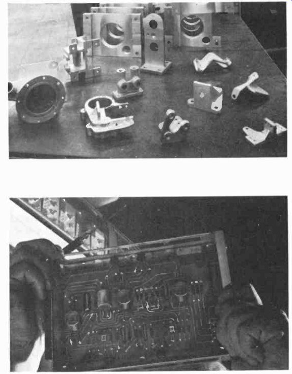
Fig. 911. Machine tools can make many precision parts automatically after
the material has been set into the machine.
This kind of decision must often be made in industry on the production line, but human operators make such decisions habitually and so often, that they hardly regard them as decisions any more. For example, an inspector will examine each product as it comes off an assembly line, and reject or accept it. If we set up the criteria for such acceptance and rejection carefully enough, there is no reason why a machine could not do the same thing, even to deciding whether the unit is worth repairing or must be rejected permanently. And indeed such automatic testing equipment is made, particularly for electronic equipment, which will check out a piece of electronic gear in all its circuits, and will reject it if specified criteria are not met. It will also indicate why the unit was rejected, record the number of the unit, the point at which it was rejected, etc. In such a testing machine, relatively few decisions are made.
But in a complicated process involving many ingredients whose application is interdependent, decisions must be made continually and rapidly. If we imagine, for example, that a cake factory would automatically weigh the materials for a batch of cakes, and would find a certain condition in the flour, which would require a bit of extra salt in the mixture, the instruments would have to make the decision to add the salt, and implement it. This kind of decision can be made with the proper logic units. Going on with the cake factory, the ingredients for a cake must not only be exact, they must be mixed in the proper order and for a specified length of time. Then they must he baked at an exact temperature for an exact length of time, provided the mixture reacts as it should. There is another decision perhaps, to decide whether the cake is of good quality.
The entire procedure of baking can be described in terms of sequences, one thing to be done after another. This is a program.
In industrial controls-control engineering-we deal with numerous programs. Some are repetitive, relatively short programs for a sequence of operations on one kind of product. Others involve a series of different products, one after another. Automatic machine tools can make a whole series of different products to precise tolerances and perform all the necessary operations-drilling, turning, milling, broaching, grinding, polishing and, what is even more important, inspecting dimensionally the final products. A self checking machine as it were.
One reason for such automated programming is that many machining operations take a lot of time to complete but require initially only one setup. The skilled operator, who set up the work, will then stand by "in case" something goes wrong with the machine or the tool bit or the product. In a machine shop where large pieces are being bored or milled, the operator sometimes stands around watching for days and days. This is unproductive time, and, if we can make the machine do the "watching" and report any failures or troubles, we can free the skilled man for other work. Figure 911 shows some of the products which such automatic machines make from programmed instructions. All of these pieces were made by the same group of machines, one after another, without human intervention. To do such a complicated job these machines must receive instructions and must compare the instructions with the stage of progress.
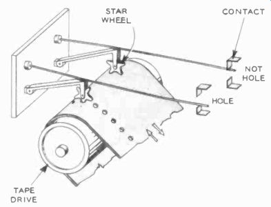
Fig. 912. One kind of punched -tape reader. Only two of the many fingers
are shown.
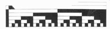
Fig. 913. Digital (binary) scale used in linear positioning.
Instructions are provided to the machine by one of several methods (this applies to processes as well as automatic machine tool products). Generally, a punched card or punched tape or magnetic tape is used. Sometimes a combination of two or more of these methods is used in various stages of a process. Punched cards have the advantage that they can be processed, punched and checked by business machines which a company is likely to have on hand for other purposes. Punched tape is somewhat faster than punched cards, and is more easily stored. And magnetic tape can be used over and over again for different programs.
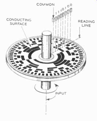
Fig. 914. Shaft-position transducer is used to convert rotation into
binary-digital form.
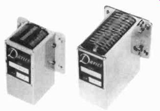
Fig. 915. Multi-channel magnetic tape heads use tube inches wide.
Most often the information is applied in binary form, since his is the way in which it can be used immediately by the logic units which process the information. Paper tape and punched cards are "read" usually by mechanical means, such as the "feelers" illustrated in Fig. 912. Other kinds of readers make direct contact through the holes. Photoelectric readers have a small photocell for each possible hole position.
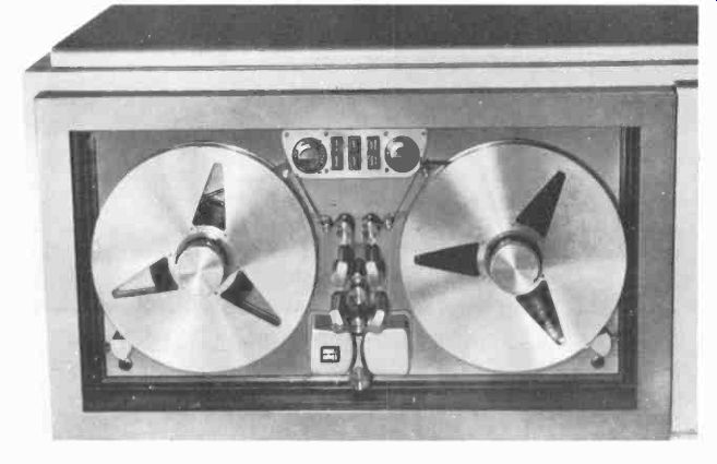
Fig. 916. Tape drive mechanisms used for control may not use the same
speeds as the recording equipment.
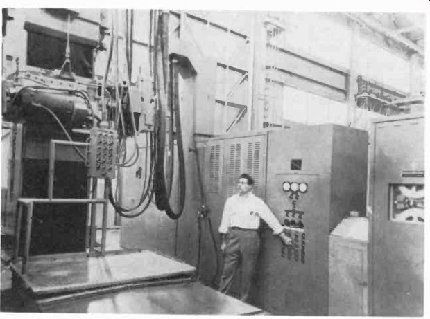
Fig. 917. Tape drive mechanism housed in cabinet at right is only a small
part of the elaborate electronic control system needed to program machine
process.
Often such instructions will be a direct means of translating analog type of information into digital form. For example, it a cutting head on a machine must describe a certain curving motion, the information is translated into digital form, giving the position for the head from moment to moment. This permits its use in the "computing" elements. If the steps are small enough, the machine head will, for all practical purposes, execute the curve accurately, and mechanical friction and tolerances make it difficult to discern any discontinuity in the product. But theoretic ally the head may have moved in step-wise fashion unless, of course, the control system includes an "averaging" circuit as, for example, the filter in a power supply, which "averages" the pulsating dc from the rectifier, thereby acting as a digital -to -analog converter of a sort.
By using scales with alternate black and white squares, and reading the positions of such squares with photocells, we can provide the machine with a mechanism which accurately reports directly in digital form, although this could be considered analog information. Again we have "chopped up" or "sampled" the analog information to provide us with digital codes which can easily be handled by the logic units, which must make the decision as to whether or not the machine is in proper position in accordance with instructions. Discrepancies can either be corrected or re ported as a malfunction to a supervising operator. Fig. 913 shows such a scale which can provide digital (binary) information with photocell readers, and Fig. 914 shows a similar device for reading shaft position. There are at least 30 different systems for positioning and reading digital data from shafts, etc.
The machines which impress information on magnetic tape are basically the same as a home tape recorder but much more versatile. Many of them use wide tape, up to 2 inches in width, and record many channels simultaneously through multiple heads (Fig. 915). Fig. 916 is a typical industrial type data -recorder mechanism. These mechanisms are built with a great deal more precision than the home recorders. Fig. 917 shows a machine controlled by a tape-recorder installation.
Their principles of recording are similar for home and industry with one exception--with the pulses of digital data it is often unnecessary to use bias for recording, although bias for erasing may be included.
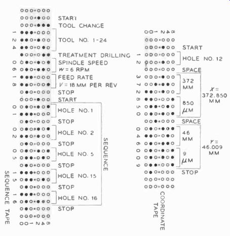
Fig. 918. Typical instructions jot machine tools as punched into tape.
Some installations may have several drive mechanisms for tape.
The machines which punch out tape instructions are similar to those which punch cards, and often a card-punch machine can be adapted to tape punching. Manual key punchers and computer-controlled automatic punchers are also used.
The instructions for a particular operation are carefully worked out though they need not be extremely complicated. For example, they can be arranged in sets of three digital sequences. one for each of three coordinates, giving the readings from three base lines in some meaningful dimension for the machine which is to use them-cutter speed, cutting depth, etc. In the case of processes, the instructions would cover say, the range and rate of change of heating, the rate of mixing chemicals, as well as the total amount of chemicals mixed, the fraction of vacuum to be pumped over a period of time, etc.
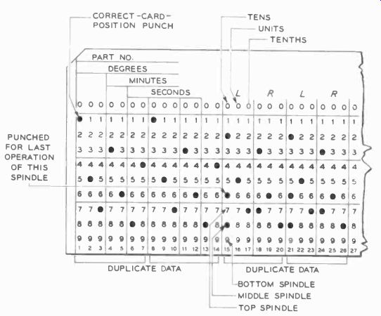
Fig. 919. Machine-tool program instruction., may be punched into cards.
Both cards and tape may he used in one system.
Fig. 918 shows typical numerical positioning data on tape, and Fig. 919 on cards, providing all the information needed to locate a machine cutting head exactly. The tape or card signal can be fed directly to some logic circuits, such as OR, NOT, NORNND and MEMORY, to determine whether the control system should take action to reposition the head or, in the case of cards, to give the signal For the next punched card to be dropped for reading.
If the information is in analog form, such as a particular voltage variation or current signal, we can read them with discriminator or bridge type circuits. Discriminators can be voltage, frequency or phase types, and all of them are familiar from communications practices: phase and frequency discriminators are used in FM communications, and voltage discriminators can look exactly like the well known vtvm circuits with the reference turned up to read other than 0. Coincidence gates ( Section 5) also can read positioning data, where the signal depends on the simultaneous activation of a number of gates. The presence or absence of a signal on the scales, tapes, cards or punched paper tapes can constitute one of the code "hits" needed for the circuits to judge action to be taken or not taken.
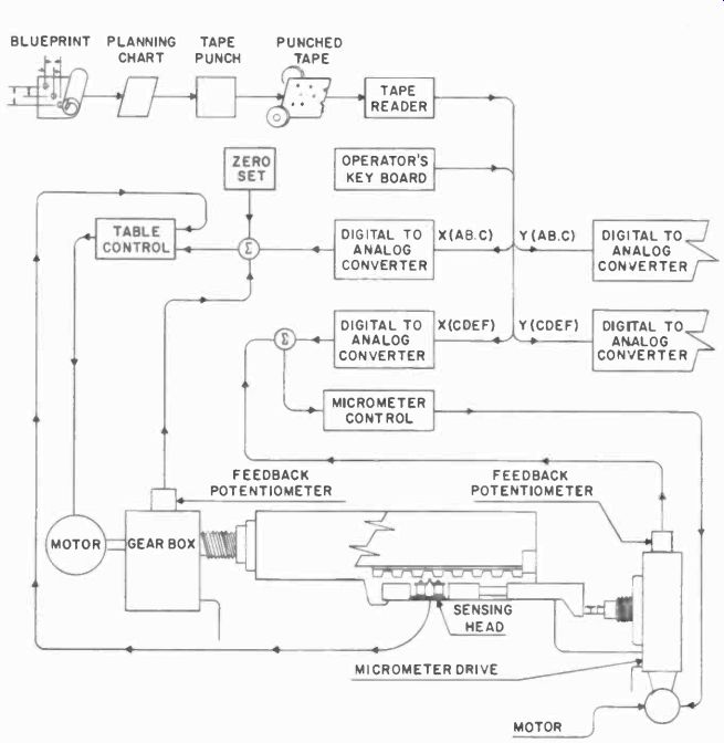
Fig. 920 shows a system used by the Pratt & Whitney Co. to position
their jig borers, and Fig. 921 a numerical positioning system of Kearfott's.
Notice that the former uses punched tape, and the latter punched cards
for data input. A number of other systems use stepping switches, their
rotary equivalents, or relays to process the information.
The planning chart (Fig. 920) goes with every system. On it the punch operator can find the proper punch code for any particular feature of the blueprint, for several coordinates.
Cost of the systems marketed for control machine tools varies with the number of operations and measurements expected, and ranges from $2,000 to $30,000.
Fig. 920. Block diagram shows all steps from blueprint to jig boring used
in numerical positioning of tool bit.
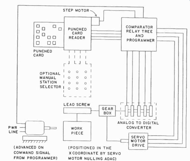
Fig. 921. This block diagram has a punched-card reader to program numerical
positioning system. Only lead screw -drive portion of system is shown.
Control systems may use computers. Suppose, for example, that we would want to know the weight of a gas in a large container.
This could be determined by weighing the container with and without gas. But suppose the weight of the gas is a very small fraction of the weight of the container, then it would be extremely difficult to measure the small changes of the weight. But the weight of the gas is proportional to three factors: temperature, volume and pressure. Volume is a constant, in a container, but pressure and temperature can vary. Thus by accurately measuring the temperature and pressure, we can, with simple arithmetical procedures, compute the weight. But suppose we try the same trick with a mixture of gases. Then we would, to obtain the weight, also have to determine the amount of each gas present, and include that in formation in the computation. Considering only this example as representative of control -system problems, you can see that it may very well be necessary to include one or more computers to provide "feedback" signals about the process, or a computer which can handle several operations simultaneously or in rapid sequence. Either digital or analog computers can be used.
The basic digital computer generally contains input, output, arithmetic, storage and control sections (Fig. 922). The lines in the diagram show the possible flow of information between sections. Input could he from magnetic or punched tape or card readers, or direct input from process or positioning circuits. output can be some form of readout, as in electronic counters, although here we use the term in a broader sense. Instead of thinking just of lights and figures and letters formed by lights, we must also include punched cards, and tape, and magnetic tape, as well as direct printed write-out by electric typewriters, operating like the teletype printers of communications, and printed tape, with bi nary codes. Direct control of processes or machine part positions may also be considered as readouts.
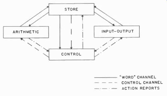
Fig. 922
The arithmetic section usually consists primarily of serial adders specially designed to fit into computer operation. But the arithmetical sections also may include logic. For example, the instructions may read like this: "If A is larger than B, add C but, if A is smaller than B, multiply by 2." In other words, to make a decision, the computer must compare the result of the product A with the product B and take action accordingly. Such a decision can be handled by a NOR circuit, for example, or a NOT gate.
The storage section will include the memory, and again there are many forms of computer memory. Besides magnetic tape, punched tape and cards, there are many other possible memories, such as the ferrite -core memory (Fig. 923), and storage tubes, which are special cathode-ray tubes with long -persistence mosaic screens: magnetic drums, and even relays.
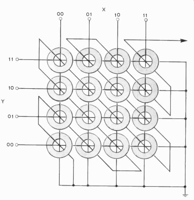
Fig. 923. A two-dimensional array of magnetic (ores will store many "hits" of
information.
The control section determines what all the other units will do.
It includes the circuits which translate the instructions for the various units, such as the arithmetical and storage units. It will also contain the circuits used to "read" and "set" memory units, erase them when necessary and select the proper memory unit.
The control section will report the result of the operation to read - out. The control section must, of course, receive instructions itself for these various functions, and these are also included in the instructions to the computer. Or there may be a fixed, cycled pro -gram within the computer so that, whenever a batch of data is received, the computer will treat the entire batch accordingly each time. This is characteristic of business machines, which are set up for one particular treatment of a set of cards, whether it be selection of certain groups, a single card, addition of data to the cards in accordance with another set of cards, etc.
Digital computers can become very large (Fig. 924). The largest computers are generally employed in military, scientific or business work; industry uses the more-moderate-sized ones. Unless a factory is automated completely and all control is centralized in a computer, it seldom is economical to use a large computer.
Specialized small computers capable of more limited operations will generally be sufficient, particularly when included in the control for one particular process or operation.
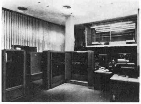
Fig. 924. Computers can rover many square feet of floor space.
Analog computers, as their name indicates, operate on analog or continuously variable information. Analog means a simile, a model, so in many industries analog computers are used to deter mine the results or reactions of certain processes or designs while they are still in a planning stage.
Analog computers operate by setting up a model in mathematical terms, and running through the process or design con figurations to determine the results. For example, if we charge a capacitor through a certain resistor, from a specified voltage source capable of delivering a minimum current, the curve according to which this capacitor will charge is well known. But suppose it were not. Then an analog computer could tell us, by drawing a curve on a recorder in its output, what the charge on the capacitor would be after a selected time interval.
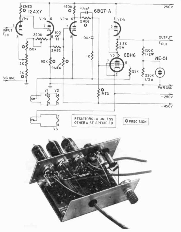
Fig. 925. Simple dc amplifier is applied in many ways in industry where
extremely low frequencies are used. Ana log computers often have decade
outputs from which gains of 1, 10, or 100 may be selected.
Or suppose we heat liquid in a vessel, at the same time increasing the pressure on the liquid gradually. A certain amount of heat leaks off from the top of the vessel, and a very small amount of the liquid penetrates the walls of the vessel. What would be the condition of stress in a particular curved section of the vessel after 3 seconds of the specified treatment? Such a problem could get very, very complicated. If we tried to work it out mathematic ally, even with a calculator, it would take considerable time for each set of conditions. An analog computer can do this kind of a job without too much strain, if the problem is properly programmed.
The increase in temperature will gradually change the pressure exerted by the liquid, and we can represent this as a rising voltage.
The increased temperature applied also can be represented as a rising voltage: the leakage as a slowly dropping voltage, as well as the heat escape from the top. The stress in the section that interests us will progress according to a formula we can work out first.
and then we can combine in some way all these variables and come out with a variable voltage which represents the strain in the metal as we apply pressure and heat.
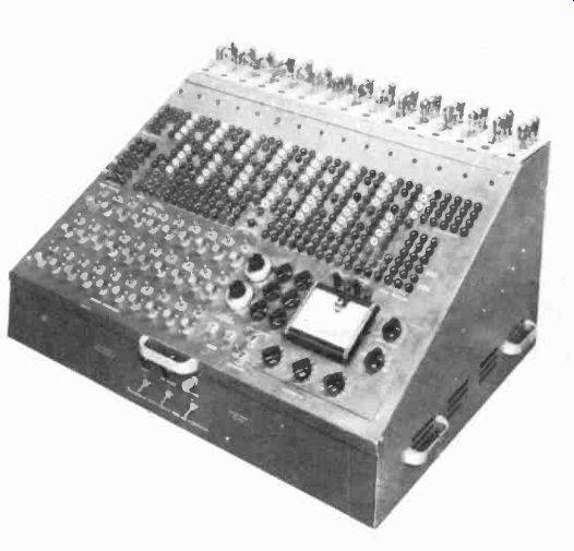
Fig. 926. Even computers are available in unassembled kits. (Heath Co.)
We cannot simply add the voltages in a direct manner, since they all represent different quantities and must be reduced to some common units, some common denominator. This may involve proportionally increasing some or decreasing others, adding a constant value to a third set of variables, or maybe subtracting a constant. All these jobs are the province of the workhorse of the analog computer, the operational amplifier.
Operational amplifier
The operational amplifier most often is a dc amplifier (some analog computers work entirely on ac) which is very stable and has a gain which can he adjusted or varied, according to a specified course of events, with external feedback loops. Fig. 925 is a schematic diagram of a relatively simple dc amplifier, with a cathode follower output voltage-regulated for stability. Not shown is the feedback loop, which is external to the amplifier. The gain of this amplifier, it can be used to control the gain, and thus the pro.
Since feedback in a negative sense can reduce the gain of an amplifier variable over a certain period of time and, with the portion of input and output voltages. If the feedback loop includes a capacitor, which gradually charges, we can make the gain of the amplifier, without feedback or "open-loop" gain, is about 50,000, methods discussed earlier in this guide, we can make the charging progress linear and the gain variable in a linear sense.
And so, with the operational amplifier, we can change voltages according to the expected progress of some quantity in a process, we can make an analogue of the process variable.
Accessories
With the operational amplifiers we need a number of accessories. Usually the analog computer contains a large number of operational amplifiers. Fig. 926 shows the Heath analog computer; on top are the amplifiers. The computer also contains power sup plies and a number of relays, which are used to delay the operation until all the variables have been set up, so that all factors in the process can start changing simultaneously. Potentiometers help provide the proper input voltages to the amplifiers. Into the jacks, each identified with the circuit to which it belongs, we can plug resistors, capacitors and other components, such as inductors, and perhaps diodes, etc., to make the feedback loop we need to build our analogues. The computer also contains a direct readout, the meter shown on the panel. A recorder can be added to provide a drawn curve readout.
Function generator
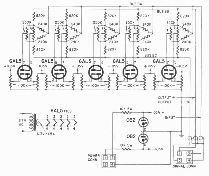
Fig. 927. vacuum-tube diodes have economically sound
characteristics for this Junction generator.
Another important accessory is the function generator shown in Fig. 927. It contains a number of diodes and bias potentiometers, with which we can set any bias we want for the diodes.
For example, if we need an input voltage to the operational amplifiers which varies according to a certain specified curve or formula, we use the function generator to create the curve by "limiting" the voltage as it increases. Visualize a rising voltage on a diode plate. At a certain point this diode will conduct, and maintain this voltage at that point. This point can be preset by arranging for a particular bias on the diode. If after that voltage has been reached, we supply more than is leaking off through the diode, the voltage will still climb. Then if we add a second diode which conducts at a higher voltage, we again at that conduction point change the shape of the voltage rise, and so on. Actually what we have then is a generator which, by varying a voltage rise according to short straight-line sections, makes this voltage rise Follow an approximation of any curve we need as input voltage for the amplifiers. Fig. 928 shows, for comparison, the curve of a sine wave, a sawtooth and one kind of curve we can generate with a function generator. We can make many different curves with the function generator, adding many diodes to make very complex curves.
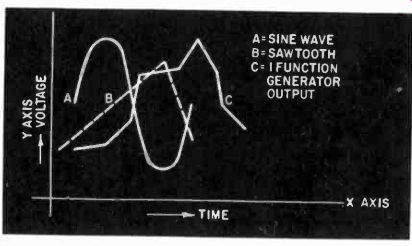
Fig. 928. Function generator can create forms for special conditions that
cannot be satisfied with sawtooth and sine waves.
These are some of the items which go to make up an analog computer: there are others, such as the potentiometers with which we can calibrate various readings on the meter, etc. Analog computers, besides being used in analyses, can be inserted directly in some process control systems where the computer, according to a preset "program," will modify the process to keep it within specified limits. It is often used in pilot plants of the petroleum and chemical industries to prevent "runaway" factors.