AMAZON multi-meters discounts AMAZON oscilloscope discounts
As it is important in a process or production line to keep count of raw materials or units produced in a certain amount of time ( Sections 5 and 6), so it is often also very important to keep an accurate and permanent record of various parameters of a process.
We may for example want to know the amount of power consumed, the variation of temperature, the amount of current or voltage employed in a process, the continuous state of conductivity of a liquid or variations in its flow. There is almost no end to the factors we may want to keep a record of for various reasons; such as being able to trace back through a process if something has gone wrong with the product. Or we may be able, through an analysis of records, to establish ways of economizing in a process.
We may also be able to use the recorder for the actual control of the process, in which case the instrument not only adjusts for changes but also informs us when and how much adjustment was made. In the case of a boiler, for example, we may want to know what the schedule of demands has been so that we can rearrange various aspects of the consumption to flatten out the demand curve.
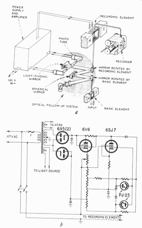
Fig. 1001. The mechanics of the deflection type photoelectric recorder
are diagrammed at (a) and the electronic portion is detailed in the schematic
at (b).
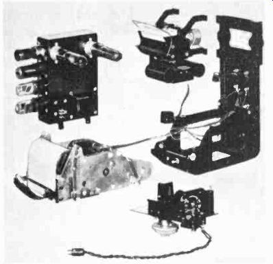
Fig. 1002. This disassembled photoelectric recorder shows the many subassemblies
that go into the complete unit.
Recorders have been in use for a long time, and there is a great variety of them. Before the application of electronics, there were many recorders in use in industry based entirely on mechanical principles. Millions of them are still at work today.
Electrical means of recording began with the galvanometer, using a pen instead of the customary pointer. This is the basis of the direct -writing pen recorders, still used often in many places.
The pen arm is driven by an oversized d'Arsonval movement, and a chart is moved electrically or by a clockwork past the pen, leaving a permanent record of the pen position, and thus of whatever value the movement was responding to.
For such a recorder the signal must be electrical. Thus whatever is measured, if it is not an electrical signal, must be converted into an electrical signal by a transducer. Transducers are used to measure pressure, temperature, vacuum, flow, mechanical position, level, oxygen or carbon monoxide content, moisture content, viscosity, density, weight, specific gravity, and all kinds of other physical and chemical factors which are significant in industrial processes. The electronic industry itself has many such applications of transducers and recorders, particularly in the manufacture of vacuum tubes. In Section 11 we will show some of the transducers used. Here we will assume that we receive an electrical signal of some kind for recording purposes.
From the simple pen-movement-and-paper-strip recorder, many other types have evolved with different methods of deflection, of making the trace and of recording. All these changes will not be reflected in a single recorder. Some modern recorders still use a version of the d'Arsonval movement with pen and ink, hut have complex amplifiers ahead of the movement or photoelectric follow-ups. Others use the same old drive, but special electrical or chemical paper and so on.
Industrial recorders can be classed as either the potentiometer or the direct-recording type. But there is only a thin line between them, and a few units fall outside or overlap both classifications.
One disadvantage of the direct-writing recorder is that the pen movement must be relatively powerful to drive the heavy pen, which limits its sensitivity. The required weight of the parts also reduces the frequency response. To increase sensitivity, we can use a sensitive mirror galvanometer for the measuring movement, amplify the motion and apply the result to a heavy pen motor, which does the actual recording.
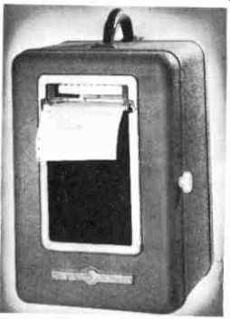
Fig. 1003. General Electric type CE recorder.
Such a system is used in the G -E Type CE Recorder (Figs. 1001-a and -b). As shown, the input element carries a small mirror. The light reflected from this mirror is divided between two photocells.
By moving the beam back and forth, greater distance and effective "pointer" length--and therefore sensitivity--are obtained. The phototubes are connected in a differential amplifier. The difference signal from the phototubes, which results when the galvanometer mirror turns and throws more light on one tube than the other, is amplified by the 6SJ7 and fed to the 6V6 power tube which operates the pen motor. Fig. 1001 shows the components in the instrument. The followup amplifier and power supply are shown at the top left in Fig. 1002, the recording motor and optical assembly at top right. Fig. 1003 shows the external appearance. Fig. 1004 shows the paper drive mechanism. Note the numbers of gears to allow a change of chart speed by shifting from one set to another. The chart is driven by sprockets which fit into holes in the chart edge, maintaining precise timing.
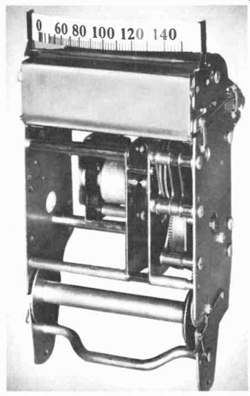
Fig. 1004. Paper drive mechanism of General Electric type CF recorder.
Fig. 1005 shows the galvanometer and lamp housing. This setup can be made very sensitive and, due to the now much greater driving power, also can respond to higher frequencies, depending on galvanometer response and other factors. This type of "amplified" recorder, uses a light beam for part of the amplification, since the long arm of the light beam quickly changes the light on the cells with a minute movement of the galvanometer mirror.
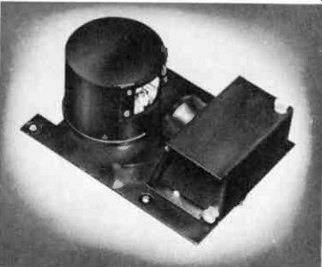
Fig. 1005. Basic instrument assembly used in photoelectric recorder with
protective cover and light source. (General Electric Co.)
A similar instrument of the potentiometer type is shown in principle in Fig. 1006. Here the small voltage that moves the galvanometer results in a current in the pen motor which is then proportional to the applied signal. This current causes a drop in resistor R, which, at one of its taps, is equal to the input voltage.
As the voltage is received from the amplifier to drive the pen motor, this portion across R is applied to the input to compensate for the signal and thus adjust the galvanometer back to zero.
Note that this system requires a spring return on the pen motor in order to maintain a balanced condition between input signal and pen -motor position.
Chart speeds of the recorders shown vary from 1/2 inch an hour to 30 inches a minute, depending on the gears used. Sensitivity can vary greatly depending on the basic units used. Frequency response usually varies from 1/2 second (1/2 cps response) for full deflection to 100 cps for the highest frequency range available. In terms of what you are used to in communications, this is a low frequency range, but other recorders will permit much higher frequency response as you will see. The recorders under discussion are primarily useful where the change they are recording is relatively slow.
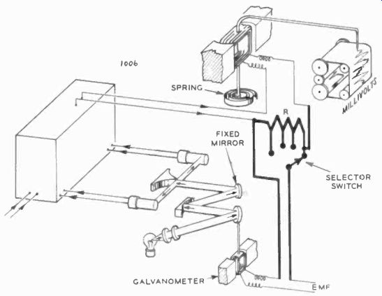
Fig. 1006. Mechanics of the potentiometer type photo electric recorder
are similar to the deflection type. Added circuitry is shown in heavy lines.
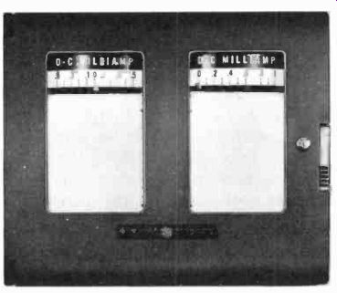
Fig. 1007. For some work too, recorders are mounted in one race for convenience.
There are many variations of these instruments including the inkless GE Type CF Recorder. The type CF uses a "tapping" system: the hinged motor pen is tapped on the paper by a small solenoid, once every 2 seconds, and types the record with a carbon ribbon on the chart. This makes the recorded line a series of points spaced so closely together they look like a line.
Where several records must be kept simultaneously, we can either install several mechanisms to write on one chart, several recorders separately or several recorders in one case. The latter is illustrated in Figs. 1007 and 1008, which show the CH-39 recorder as it appears externally and with the door open.
An entirely different approach to the problem has been taken in the Mark II twin recorder shown in Fig. 1009.
The Mark II consists primarily of a well-balanced dc amplifier, utilizing a well-regulated power supply, driving the pen motors.
Because the amplifier is balanced all the way through from input to output, drift, so characteristic of dc amplifiers is avoided, since it is most likely equal in both halves and thus cancelled.
Sensitivity of this kind of recorder is limited only by how much amplification we manage to apply. Frequency response is still limited, since we are again dependent on a pen motor as a final recording means. Not only the inertia of the motor parts is responsible for the limitation in frequency, but we must also consider the writing speed. If we move the pen too fast across the paper, no trace will result. Move a pen fast enough across a sheet of paper, and only a scratch will result!
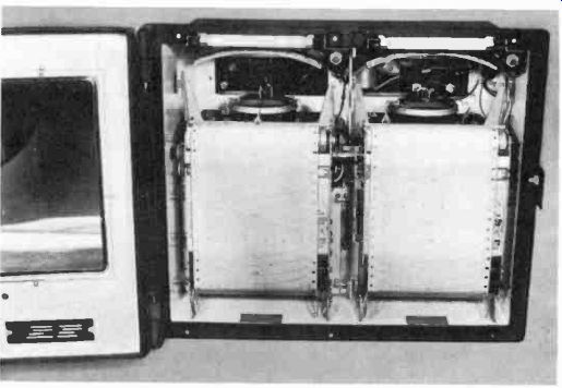
Fig. 1008. Front door opens for routine maintenance and roll -chart replacement.
Various methods have been worked out to overcome this. One of them is to use special electrically -conductive paper which has a platen behind it. When the "pen" arm, here carrying a stylus, is supplied with dc, a chemical change takes place in the paper due to the current conducted through the paper, and leaves a permanent trace. A similar approach is to provide the stylus with a small heating element and to use a paper which is sensitive to tempera ture. Where the hot stylus touches the paper it leaves a chemically-changed surface which is dearly distinguishable.
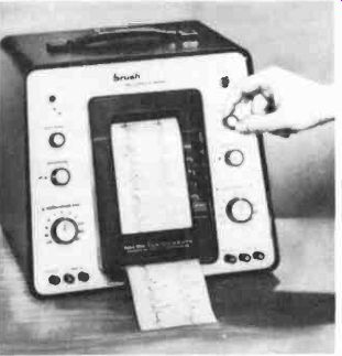
Fig. 1009. Dual electronic recorder has both traces on one tape for easy
comparison.
These special recording means have permitted writing speeds up to the equivalent of 2,000 cycles on a chart width of about 2 inches, which is quite high. Pen motors can be driven this fast if they are given enough power, but this is not a universal method.
For higher frequencies we almost always use oscillo-graphs.
The "potentiometer" recorder previously shown is not typical.
Most potentiometer recorders operate according to the principle illustrated in Fig. 1010. The incoming signal can be considered as a leg in a bridge circuit. One other leg of the bridge is a variable voltage. The "galvanometer" of the bridge is a null detector, and this can be anything from a meter movement (as we have seen) to an amplifier-pen-motor system operated by ac. The null detector perceives the unbalance in the bridge and adjusts the voltage accordingly, meanwhile also moving the pen. As the voltage applied to the input terminals varies, the pen follows it and leaves a permanent record on the chart. It would be easy enough to add another potentiometer to the mechanism, also moving with the pen, to control some other devices. This is the very simple principle of the control recorders commonly used in industry.
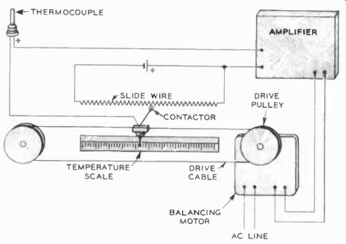
Fig. 1010. The principle of most potentiometer type instruments is as
shown here. An addit. Slide wire can be added as control circuitry.
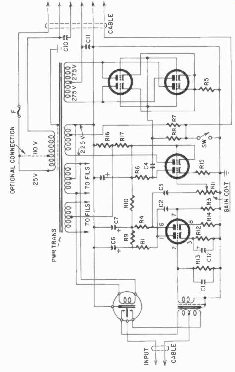
Fig. 1011. Schematic diagram of Brown Electronik recorder has some unfamiliar
circuitry.
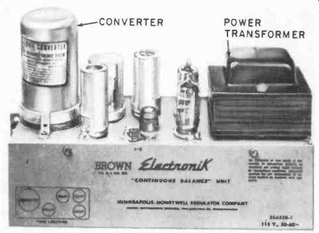
Fig. 1012. This is a view of the recorder amplifier of Fig. 1011.
Fig. 1011 shows the input system, with chopper circuit, and ac operated output of a typical industrial recorder. The instrument is shown in Fig. 1012. It uses a wide chart. With a potentiometer system we can move the pen over a much larger distance than with just a d'Arsonval pen motor. Notice also that the lines on the d'Arsonval type are curvilinear, because the pen executes a circular motion. For the potentiometer instrument just discussed this is not necessary, since the pen rides on a rail or rack and thus moves in a straight line.
Having such a wide chart, we can use the recorder for multiple records. Suppose we do not need a continuous graph, but only a graph of approximate change, with a recorded point, say, every few seconds. Then we could just as well use the "typing" approach and type a dot when we wish to record.
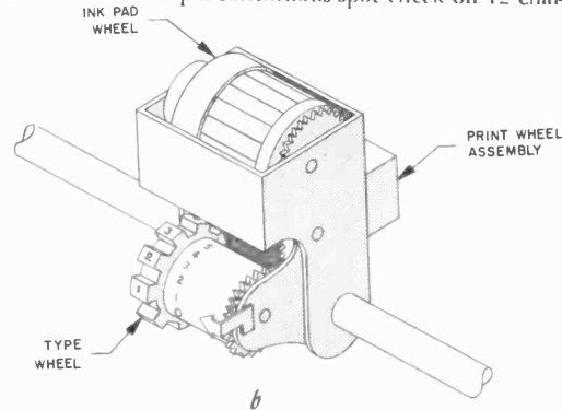
Fig. 1013. Print -wheel recording mechanism allows many channels to be "read".
Only samples are recorded. Most transients go un-indicated.
If we give the instruments several inputs (as many as 12) and make the "pen" a little printing wheel (Fig. 1013) with 12 distinct symbols or numbers on it, we print these each in turn as we turn the switch through all the inputs and turn the wheel with it synchronously. Thus if channel 1 is on the input, the wheel will present symbol 1 to the chart, the potentiometer will move the printing wheel to the proper position, and a solenoid will print the number. As we move the switch to position number 2, automatically the wheel presents symbol 2 and, after it is in a rest position, prints the number 2 symbol, and so on. If we make the switch an automatically stepping type, which also steps the wheels with it, then we will keep a continuous spot check on 12 channels on one chart. This is the system used in the Minneapolis -Honey well Brown multichannel recorder. Notice in Fig. 1013 that the pointer has a number near it, and that right next to this number you can see the printing wheel.
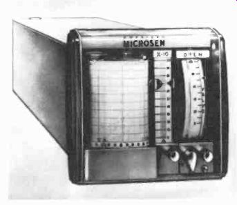
Fig. 1014. This recorder-controller uses the principle diagrammed in Fig.
1015.
Most industrial recorders now being purchased and installed are of the potentiometer type, although there are numerous variations in the method of moving the pen, in the balancing system, in the paper and the recording means, in the amplifiers, etc.
One which is particularly different is the Microsen recorder-controller. Fig. 1014 shows the instrument, and Fig. 1015 illustrates the basic principle. An electromechanical sensing element consisting of a coil suspended on a rotating beam is placed in the field of a permanent magnet. Current from the transducer passes through the coil, and tends to change its relative position with respect to an oscillator coil. The movement of the vane increases or reduces the oscillator current. This varies the current delivered by the oscillator to a rotary solenoid type motor. The solenoid motor increases the tension on a spring, which counteracts the effect of the current in the sensor coil (which would otherwise keep on traveling). The position of the lever which applies the tension to the spring is then proportional to the input current in the coil, and the end of this lever carries the recording pen, which here executes a vertical motion.
In Fig. 1015, the "amplifier'' section contains both the oscillator and an amplifier, and more besides. The Microsen, in so far as we have discussed it, has exerted what is known as a proportional action only, and the output signal, and hence the pen position, is a proportion or multiple of the input signal, depending on the sensitivity used. The instrument has a repeatability accuracy of 0.1%.
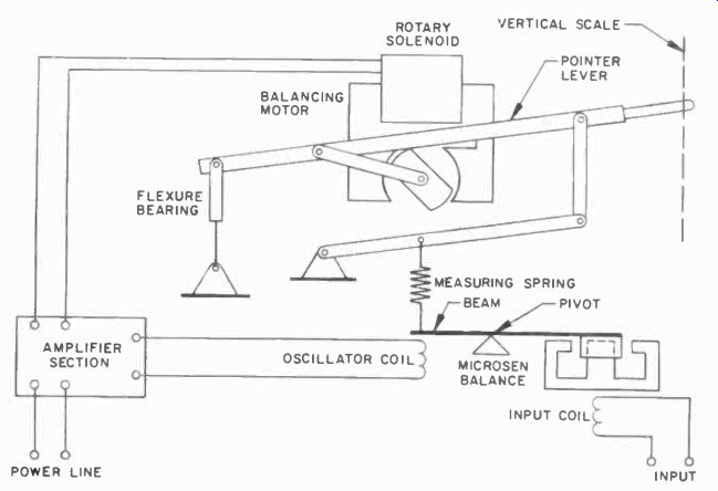
Fig. 1015. Principle of operation of the Microsen recorder is simplified
in this diagram.
The pen has indicated only how much adjustment has resulted from the input signal; in other words, we have a record of the control action taken by the instrument.
But the Microsen can do a great deal more. It can also take action in relation to the rate of change of the input signal, and this is important in dealing with a "runaway" process. If the process tends to deviate more rapidly, we can set the Microsen so that a greater signal is received from the output, thus allowing, for example, a rapid shutting of valves when this is most needed.
Fig. 1016 shows the controller unit of the Microsen.
Still another form of recorder is shown in Fig. 1017. Here the input signal is applied to the control windings of two saturable reactors in a bridge circuit, and the bias of the two reactors is so arranged that the signal will aid the bias in one and oppose it in the other, causing unbalance. Amplified, the resultant signal is then applied to an ac amplifier which controls the balancing motor by means of saturable reactors.
Many other systems use their own special methods for one function or another. The Leeds & Northrup recorders use a gravity kind of balancing system for the followup of a galvanometer pointer. Others have photoelectric followup systems with pen carriages (rather than a rotating pen motor) or use a small change in capacitance in the input measuring element, and so on.
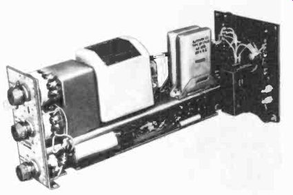
Fig. 1016. The electronic circuits of the Microsen recorder are quite
compact.
One unusual group is the X-Y recorders, found mostly as the output of analog computers, but which could become very useful in checking out complex control -system functions. These recorders, as their name implies, are capable of recording in two axes, X and Y, and can draw graphs involving any variation of two independent or dependent inputs, or one (X) can be used as a time base. Originally slow, some X-Y recorders can now plot a curve in a fraction of a second with great accuracy. However, these are not primarily industrial recorders, and we will not discuss them further except to say that their moving systems are akin to the potentiometer type controllers and recorders.
So far we have shown means of making multiple recordings which consisted basically of using several instruments on the one hand, or time-dividing the recording between a number of signals.
There are still other ways of doing this. Particularly (but not exclusively) in rotary chart recorders, as many as six overlapping pens make simultaneous recordings. A typical single -pen recorder made by Foxboro is shown in Fig. 1018. The instrument has a cam-like device. This is used to obtain an output signal which has some of the "rate" characteristic - the greater the deviation from a set point, the greater the output signal, due to the spiral shape of the cam. This recorder is then also a controller.
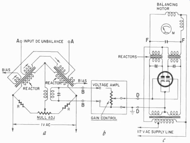
Fig. 1017. Another recorder circuit makes use of saturable reactors as
input and control elements.
Another method used to make multiple recordings consists of four separate pen motors each operating its own pen arm. The arms are all pivoted at the same point and operated by linkages.
This allows us to make the arms slightly longer progressively, yet make a common reference line for the pens which takes the form of a mathematically simple curve.
Circular chart recorders are usually slow and most likely used where a continuous process is watched, such as the stead pressure in a boiler, etc., which is continuously attended by engineers. The record shows when the heavy loads are applied, so that the engineers may schedule loads to even up the demand.
In a large operation requiring more records than can be satisfactorily handled by a multiple recorder, recorders in banks are installed, such as the group of Foxboro units shown in Fig. 1019.
These are designed as draw -out units, so that their internal structure is easily accessible for service and maintenance.
Service work on a recorder depends a great deal on the unit you are dealing with. In many cases the ink supply of recorders must be periodically renewed, but the so-called inkless recorders may need a new carbon ribbon instead. On the other hand, the styli of recorders using some chemical or electrical recording medium need no attention to speak of.
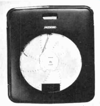
Fig. 1018. Circular chart recorder may rover an hour, day or week, depending
on details required for process.
Recorders in industry are practically always designed to fit into the environment, and delicate internal components are adequately protected. Where this is not the case, a recorder may need periodic cleaning. This can best be done with a set of cleaning brushes and a low-pressure air supply. (Any strong air blast will easily damage delicate parts.) The air used must be dry and free of oil and particles. It is always better, if possible, to remove a recorder to a clean workbench, where maintenance can be done without danger of physical damage to the recorder, than to service it in place, unless it was specially designed for this type of maintenance. Be sure to follow the manufacturer's recommendations on recorder maintenance.
One chore is chart replacement. This again varies a great deal with the recorder used. The circular-chart recorders are the simplest. The chart is held on the spindle with a special nut or clip, and all that need be done is to remove the old chart, slip the new one in, and fasten the nut or clip again. All recorders have some means of removing the pen from the chart for this process.
In many cases this is a simple hinge arrangement in the pen arm, while in others the entire pen-arm mechanism swings out of the way. A typical chart-removal procedure is shown in the series of pictures of Fig. 1020. In any case, the manufacturer's manual will give detailed chart-changing procedures.
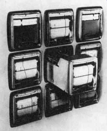
Fig. 1019. This bank of recorders is installed on slides easily accessible
for maintenance.
Actual repair to the amplifiers or the mechanism of a recorder must be done in 90% of the cases with the recorder removed from its case and normal location. Treat the recorder electronic gear like any other delicate instrument.
Be especially careful to do no violence to any of the mechanical parts of the recorder-it is a safe bet that they are much harder to replace than the electronic components!
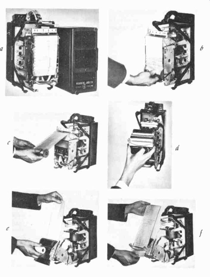
Fig. 1020. The chart-removal sequence: remove race (a), pull out take-up
spool (b), remove unused chart paper (r), remove empty spool (d), start
new roil (e), thread new paper through guides (f). Procedure is similar
for most recorders and is detailed in their individual maintenance manuals.
(General Electric Co.)

Fig. 1021

Fig. 1022
Oscillographs
Oscillographs are in a class by themselves and will not normally be encountered in the industrial plant, but rather in the plant laboratories, where they may see some rather heavy use. They are expensive instruments, and anyone not contemplating frequent [....]
In any case, the elements are made so small - they are scarcely thicker than a pencil, not counting the magnet-that many of them will fit into one instrument. Often one magnet serves for a number of galvanometer coils. The optical system of such an oscillograph is arranged to produce very thin collimated beams of light, which can be re-projected from the galvanometer mirrors and maintain their thin beam character, to produce clean traces.
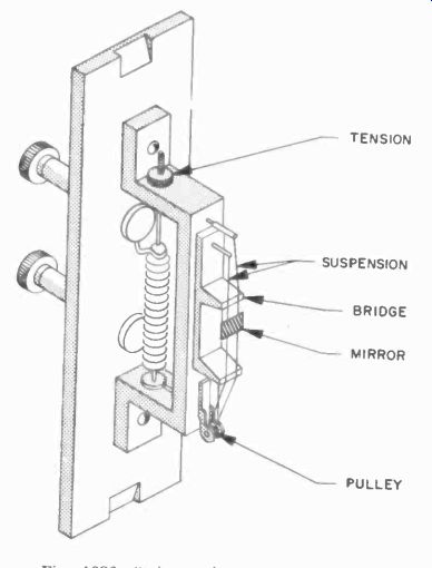
Fig. 1023. String galvanometer assembly depends on the magnetic field
around the wires to twist the mirror when in place in their normal permanent
magnetic field.
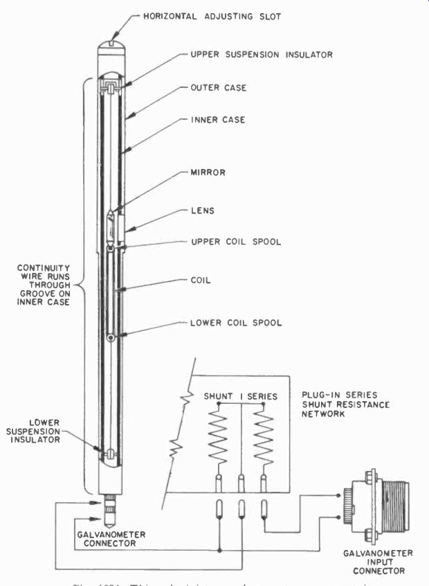
Fig. 1024. This subminiature galvanometer movement is shown nearly twice
its normal size. Some models will indicate at 5,000 cycles.
One modern oscillograph is so versatile and easy to use it could be regarded as an industrial recorder rather than a laboratory instrument, although it has the sensitivity and frequency response of the typical laboratory instrument. This is the Visicorder, made by the Heiland Div. of Minneapolis Honeywell. The thin galvanometers used in the instrument are especially compact. A section of the galvanometer, a small elongated coil which rotates on suspension wires, is shown in Fig. 1024. With such a small coil there is no question of inserting a core inside the coil as in the normal d'Arsonval movement but, since the coil is so small, we approach a perfectly homogeneous field closely enough without it.
These galvanometers for the Visicorder can be obtained in a great variety of sensitivities and frequency response. Elements vary from a frequency response of 0-24 cycles, flat within ±5% and a sensitivity of 6.7 microamps per inch to 240 cycles and 77 pa per inch, for the electromagnetically damped type, and from 0 600 cycles and 2.63 pa per inch to 0-4800 at 37 pa. Note that as the frequency response increases, the current per inch of deflection goes up. To obtain greater frequency response, the suspension must be tighter, and thus requires more torque and greater current to turn the coil.
It must be pointed out that the figures given above are meaningless unless we know we are speaking about a specific galvanometer system, as we are here. If we say the deflection is so much per inch, it gives no performance data unless we specify the length of arm at which we measure the deflection. Deflection is the result of the rotation of the current-driven coil, at a certain distance.
The greater the distance, the greater the deflection with the same rotation. In the Visicorder we have an arm of 11.8 inches. This is not an industry standard; each manufacturer builds into his instrument as much arm as the physical size and the optical system will allow, which gives him the most advantageous deflection per unit current figure.
The Visicorder is different in another important aspect from most oscillographs in that it uses a system of direct writing in an optical sense. The optics for the galvanometers are designed so that the instrument can use a high-pressure mercury-vapor light source, which is rich in ultraviolet. The paper used is related to blue -printing paper, which is also affected by such light. In this case, however, no developing solution is needed; the process is immediate and dry. Ultraviolet leaves a dearly discernible trace on the chart.
Since normal glass does not transmit a sizable portion of the ultraviolet spectrum, the Visicorder has optics made from a special material. For a time base, the Visicorder contains a built-in flash lamp, so that no galvanometer need be used for a timing record.
The timing lamp also can produce fine grid lines on the chart if need be, so that immediate reference lines for reading the record are available, which are spaced at the timing-flash points. This again is a very unusual feature for oscillographs.
Up to 24 galvanometers can be accommodated in the instrument. With this kind of sensitivity and frequency response, no amplification is used. With direct -recording and amplifier industrial recorders, we generally have an input impedance which varies from 2,000 ohms to several megohms. Although the lower end of this scale can seriously load a source being recorded, the high end certainly does not. However, with galvanometers we are not this fortunate. Galvanometer resistance for the Visicorder, for example, varies from the 21 ohms of the very sensitive galvanometer to a maximum of about 112 ohms for the least sensitive unit with the high-frequency response. This means that, unless we have a low -impedance source, the galvanometer will most certainly load the source. This can be avoided by using a matching transformer or a cathode follower with the oscillograph. The cathode follower is preferred because it can also respond to dc, and can be made virtually linear over the range of the galvanometer. The transformer is easier to use but is likely to introduce some nonlinearity in the response, particularly at the low frequencies. If extreme accuracy is needed over the entire range, use a cathode follower and compensate for zero-set.
Recording oscillographs are used in many places besides the industrial laboratory. They keep written records in such applications as missile performance and nuclear reactor control as well as the readout of computers. In industry, they have been particularly useful for checking circuit-breaker and thyratron performance and similar applications where they are the most convenient means of showing the interrupting speed of the devices tested.
Where frequencies greater than 5,000 cycles per second must be recorded, we have to resort to the inertialess cathode ray tube (CRT) or the oscilloscope. This is primarily designed for viewing. However, with a properly designed camera attachment, we can turn the oscilloscope into a very efficient oscillograph. This does not mean it is always best to use, as we shall see.
Oscilloscope photography While an experimenter can often do a satisfactory job of photo graphing the traces on a cathode-ray tube (CRT) screen by set ting a camera in front of the scope and making the room dark to minimize reflections, such a method would be clumsy in a laboratory or industrial setting. Many special cameras have been developed for industrial use to provide a series of oscillographs with very high frequency response and sensitivity. They have enough disadvantages, however, that recording oscillographs are not in immediate danger of being replaced with oscilloscopes and cameras. It is difficult, for example, to do a good job of getting more than 20 traces on an oscilloscope screen, and for high-speed response it might be very difficult to get more than two. In fact for transients it is impossible to get more than one, per each CRT gun, if the transient must be observed in its entire length. Then all methods of "switching" and "chopping" sweep interfere with the proper presentation. With a good oscillograph, 20 transients could be observed simultaneously! Several systems can be used, and cameras have been developed for all of them. There are two Dumont cameras, one of which is shown in Fig. 1025. These differ in that one uses the Polaroid -
Land system, making direct prints in less than a minute (but of course it must be idle during the development) while the second uses a rapid-sequence camera which takes many sequential shots on standard 35 -mm film. Note that these camera mounts have been so designed that the user can get full binocular vision of the screen while taking the pictures, so that necessary adjustments can be made without removing the camera.
Another system of CRT photography is used when a continuous record of considerable length is desired. In that case the sweep circuits of the oscilloscope are not used, and the spot is deflected only in the vertical axis, while a film travels by the screen rapidly in a horizontal direction. Cameras are made which can utilize several hundred feet of 35-mm film this way, giving a continuous record which can last minutes or even hours, depending on the film length and speed.
For high-speed photography, a CRT with a special phosphor, P11, is used. This blue -white phosphor is used because films are generally very sensitive to this color, permitting high "writing" speeds. The customary green phosphor is fine for observation, since the human eye is especially sensitive to green, but films are often not. Color shots of CRT traces are now possible in a reason able exposure time with the new high-speed color films, and several manufacturers are now building cathode-ray tubes for special displays with a number of colors, somewhat on the principle of television color tubes. These are used where a number of traces must be clearly distinguishable from each other, and color film is needed or the distinction is lost.
CRT photography is not an everyday practice in industrial electronics servicing itself, but it can he a valuable ,tool when appropriate. For example, if equipment or a process needs adjustment and there is some reason why it should not be operated with this defect for any length of time, brief checks with an oscilloscope camera can be a valuable aid in adjusting. It can also provide a record of the kind of malfunction that takes place in the equipment, so that it can be analyzed without having to continuously operate equipment that may be seriously damaged.
Cathode-ray oscillographs which are designed with photography in mind, as most good -quality professional scopes are, will include circuitry to increase the intensity of the trace as needed. Their normal operating intensity for viewing is not as great and, if the tube were operated at the great intensity used for photography, the phosphor would soon deteriorate.
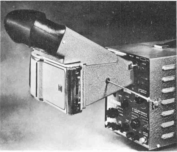
Fig. 1025. Oscilloscope camera shown here uses Polaroid - Land film.
Circuitry for intensification is simple. Sometimes it consists simply of boosting the accelerating voltage on the final anode, but most often it simply increases the positive voltage on the grid of the CRT. With such means and the new films and developers which allow film speeds up to 3,000 ASA, very high writing speeds can be obtained.
Increased writing speed
To obtain even greater writing speed we can record with an electron beam directly on a sensitive photographic emulsion. To do this, the photographic plate is inserted into special tubes which have a removable front. This means that we must have a door which can hold a good vacuum, for each time we change film we must evacuate the tube with a set of high-vacuum pumps. Such oscillographs are in use only in laboratories which specialize in testing such things as impulse generators in which an artificial lightning flash is created which lasts only a fraction of a micro second.