Many electronic control systems may be implemented with ICs. These range from simple, sensitive DC relays, such as the one described here in Section 1, to highly sophisticated setups in which amplification, delays, clocking, gating, phasing, and holding all may play a part, and in which a number of ICs may be used. As an example of the utility of the IC, a DC relay (as in Fig. 1) can be sensitized 10,000 times by an IC that is only about 1/100 the size of the relay itself and which may easily be packaged with the relay. In fact, there are commercially available relay-IC combinations in a single TO-5 transistor can.
This section describes ten illustrative control circuits em bodying ICs. Complex arrangements have been avoided, the setups shown here being the simple ones that most students and experimenters might prefer for test and observation. A variety of ICs are usable in these circuits, even when a specific IC is shown in the schematic.
In some cases, it might be desirable to have a higher input impedance than is afforded by a specified IC, in order to minimize loading of the control-signal source. Here, an IC having FET input may be employed, and the corresponding high input impedance will be comparable to that of a vacuum-tube circuit, or a FET stage may be operated ahead of a conventional IC.
1. SENSITIVE DC RELAY
Fig. 1 shows a simple circuit in which the IC is employed as a stable DC amplifier to boost the sensitivity of a milli ampere-type DC relay. The Type CA3036 IC consists of a dual Darlington pair. This is a pair of direct-coupled amplifiers in which the output (emitter) current of one transistor flows directly into the input (base) circuit of the next transistor. The two Darlington stages are coupled together by means of the external jumper shown, in Fig. 1, connected between terminals 2 and 8. The net result is the equivalent of a single transistor having a super beta.
A DC input signal of 0.5 V at 0.5 µ,A is amplified sufficiently by the IC to close a 2-mA, 100-ohm DC relay. (This may be an inexpensive model-control relay, such as Lafayette No. 99 T 6199.)
The equivalent DC input resistance of this circuit is 1 meg ohm when the sensitivity control R1 is set to zero resistance (maximum sensitivity). The control factor of this circuit (ratio of relay power to signal-input power) is 1600. Additional sensitivity may be obtained by operating a dc amplifier IC ahead of this control circuit.
Higher-current DC relays may be used in the output circuit of this setup, and the DC input-signal voltage will need to be boosted proportionately. The power gain of 1600 will hold, however.
2. SENSITIVE AF/RF RELAY
The wideband characteristics of the Type CA3010 IC are utilized in the setup shown in Fig. 2 to obtain an ac relay capable of audio-frequency and radio-frequency operation.
In this circuit, an input signal of 1 mV rms at 0.1 µA is amplified sufficiently by the IC to actuate the rectifier-relay circuit connected to the IC output.
The relay rectifier converts the ac output of the IC to direct current to close the relay. This rectifier consists of two small-signal silicon diodes, X1 and X2, blocking capacitor C3, and relay bypass capacitor C4. The latter capacitor not only boosts the relay current, but also prevents relay chatter at low signal frequencies.
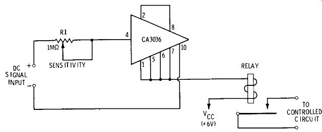
Fig. 1. Sensitive DC relay.
The equivalent input resistance of the circuit is greater than 10,000 ohms. At 1000 Hz, the useful power amplification ratio of required relay power to rms signal-input power is 10,000. The relay is a 1-mA, 1000-ohm unit (e. g., Sigma Series 5). This amplifier-rectifier setup will be found adequate for many wideband control operations. The high-low capacitance coupling arrangement (C1-C2) should provide optimum in put conditions. In some applications, in which operation is largely high radio-frequency, it might be advantageous to reduce the capacitance of C3 for better relay sensitivity.
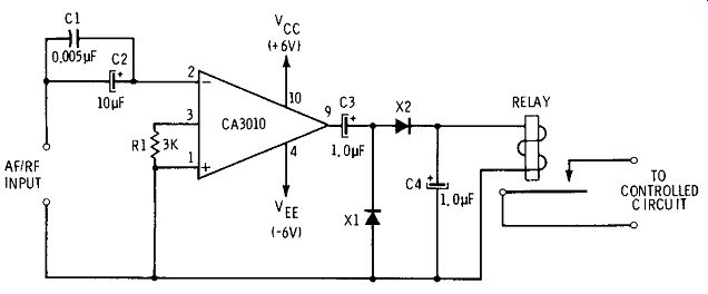
Fig. 2. Sensitive AF /RF relay.
3. SELECTIVE AF RELAY
In some applications, especially those involving switching operations for a number of points, tuning of the control circuit is desirable. This then permits use of switching signals at various frequencies to close separate relays. Another use of tuning is to insure operation of the relay at only one control frequency, and effective ignoring of signals at all other frequencies. Fig. 3 shows the connections for a tuned audio-frequency relay.
In this arrangement, the amplifier-rectifier setup is essentially the same as that described in preceding Section 2.
The IC AF amplifier itself secures its sharp tuning by means of a twin-T selective network (R2-R3-R4-C2-C3-C4) connected in the negative feedback loop (see Section 6, Section 2, for a complete explanation of the selective operation of this type of amplifier and for instructions regarding calculation of the resistance, capacitance, and pass frequency values). Where desired, the selectivity of the circuit may be sharpened by means of positive feedback through the R5-R6 signal divider.
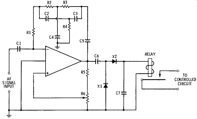
Fig. 3. Selective AF relay.
The sensitivity of the circuit depends upon the voltage gain of the IC and upon the maximum positive feedback that may be employed (through adjustment of potentiometer R6) before the setup oscillates. Response is limited in general to the audio-frequency spectrum, since beyond about 20 kHz, leakage through stray capacitances in the twin-T net work degrades performance of this network.
This selective AF relay will be attractive particularly to users who need several control channels, each operated at a different control frequency. The separate-channel circuits are greatly simplified by the small-sized relay-IC combinations.
4. SOUND-OPERATED RELAY
Fig. 4 shows the connections for a sensitive IC relay actuated by sound. This is not a selective circuit, but is an arrangement that is capable of operating from sounds be tween 100 Hz and 5 kHz in frequency.
The IC may be any operational amplifier having high voltage gain and wide frequency response. The microphone (MIC) is preferably a low-impedance unit. (If a high-impedance microphone is to be used, the IC should have FET input; otherwise, a FET amplifier stage must be operated ahead of the IC.)
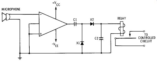
Fig. 4. Sound-operated relay.
The ac output of the amplifier is rectified by the dual-diode (Xl-X2) combination (the diodes may be small-signal silicon or germanium units), and the resulting direct current deflects the relay. The latter may be a 1-mA, 1000-ohm unit, such as that employed in the AF/RF relay, Fig. 2. Coupling capacitor C1 serves principally for DC blocking and should be high (e.g., 10 µF), and C2 serves as a relay bypass unit (typically 10 µF). For simplicity, the entire circuit given in Fig. 2 may be used in this application simply by connecting the microphone to the signal-input terminals. If gain control is desired, a suitable potentiometer may be connected between stages of the IC. When selective operation is desired, as when the relay is to be actuated by a whistle of particular pitch, the IC amplifier may be tuned to the required pitch by means of a twin-T negative-feedback network (see Fig. 3 and Section 3).
5. PROXIMITY RELAY
The applications of capacitance relays and touch-plate relays are well known and need no repetition here. The actual construction of such a relay, however, is greatly simplified through use of an IC, which supplies the high sensitivity obtained from a large number of separate stages usually assembled for such relay operation. Fig. 5 shows a sensitive setup that may be used either as a capacitance relay or a touch-plate relay.
In this arrangement, the high-gain preamplifier, described in Section 2, is coupled ahead of the sensitive AF/RF relay described in Section 2. The high input-signal terminal of the preamplifier is connected to a small touch plate ( usually, a 2- or 3-inch-diameter metal or foil disc). When this plate is touched by the operator, his body couples into the circuit enough energy from the stray fields commonly found in all locations that the relay closes. When the entire system is operated at maximum sensitivity, touching the plate should not be necessary; merely placing the hand near the plate should couple-in enough energy through capacitance effects to operate the relay.
For adjustment of the sensitivity of the system, a suitable gain-control potentiometer may be installed either between the preamplifier output and the relay-amplifier input or be tween the stages of either one of those units. In most in stances, however, the system will be operated "wide open," as shown in Fig. 5.
6. PHOTOCELL AMPLIFIER
Fig. 6 shows the connections for a simple IC DC amplifier for boosting the voltage output of a self-generating silicon photocell (solar cell). This amplifier employs only two out board components: sensitivity-control rheostat R1 and negative-feedback resistor R2.
The Type CA3010 IC, operated in this configuration, gives a DC voltage gain of 4 when R1 is set to its lowest resistance (maximum amplifier sensitivity). The photocell (PC) is poled for positive DC output to the inverting terminal of the IC. In a typical operating condition (the PC is a small, in expensive silicon cell, such as an International Rectifier Type SlM; R1 is set for maximum sensitivity), bright sunlight on the cell ( or equivalent artificial illumination) gives 2 volts (open circuit) at the DC OUTPUT terminals.
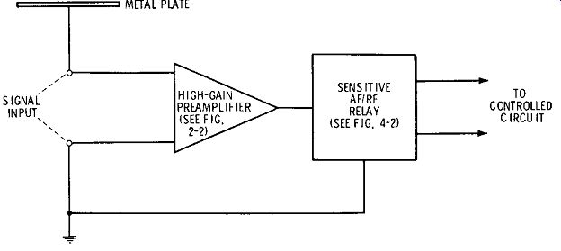
Fig. 5. Proximity relay.
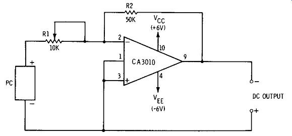
Fig. 6. Photocell amplifier.
For increased amplification of the photocell voltage, two or more identical DC amplifier stages may be operated in cascade. ICs other than the CA3010 will give similar operation; however, the experimenter must keep in mind that the maximum output-voltage swing is determined by the IC output characteristics and the amount of negative feedback introduced by R2. Cascading will increase the overall sensitivity of the system, making it possible to obtain a given DC output voltage with a low level of illumination, but will not increase the maximum obtainable DC output for a given IC.
7. SIMPLE LATCH
Fig. 7 shows the connections for a latch-switch circuit. Operation of this type of circuit is identical with that of the familiar electromechanical latching relay: A momentary signal switches the circuit ON, and it then remains ON (unless the DC power supply is momentarily interrupted). The next momentary signal that comes along switches the circuit OFF. Thus, if a chain of input-signal pulses is applied to the circuit, the latter is switched ON by every other pulse.

Fig. 7. Simple latch.
The basis of the setup is a flip-flop type of IC. This device has three inputs (S, set; T, clock; and C, clear) and two out puts (1 and 0). Only one of the outputs is used in the setup shown in Fig. 7. If the circuit, as shown, has zero output, a suitable pulse applied to the T input terminal will cause a voltage to appear at the SIGNAL OUTPUT terminals. This output voltage then remains present and unaltered even after the input pulse has disappeared. The next input pulse will switch the flip-flop OFF, i. e., will cause the output voltage to fall to zero. Thus, the output appears in response to alternate input pulses.
The output pulse may be used in various ways. For example, it may be used to fire an SCR circuit, or it may be applied to the input of a sensitive DC relay of the IC-amplifier type shown in Fig. 1. With some types of flip-flop, the relay itself may be connected to the output terminals.
Only one output terminal, 1, is in use in Fig. 7. Actually, the O terminal might as well have been used: the O terminal is switched ON when the 1 terminal is switched OFF, and vice versa.
From the operation just described, it is seen that the latch circuit is a scale-of-two counter. It delivers one output pulse for each two input pulses. If the OUTPUT terminals are connected to a counter, the counter will divide the number of input pulses by 2. If two such latches are operated in cascade, a divide-by-4 arrangement is secured, the signal output consisting of 1 pulse for each 4 successive input pulses. In a similar manner, the input-pulse total may be divided by 8, 16, 32, etc., by cascading the appropriate number of flip-flops.
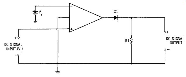
Fig. 8. Threshold circuit.
8. THRESHOLD CIRCUIT
In the setup shown in Fig. 8, the DC SIGNAL OUTPUT is zero until the input-signal voltage (V1) exceeds the value of a selected reference voltage (Vr). This action is obtained by using both inputs of a differential operational amplifier.
As long as the two voltages, V1 and Vn are equal, the amplifier output is zero. When V1 is higher than Yr, however, the amplifier symmetry is destroyed and the DC output is V1 -Vr.
The reference voltage thus serves as a threshold.
When V1 is lower than Vn the output of the amplifier is positive. At this time, however, the back-connected, high resistance, small-signal, silicon diode (Xl) blocks the cur rent through output resistor R1, and there is no output voltage drop across this resistor. When V1 = Vn the output is zero and there also is no drop across R1. When V1 > V n how ever, the amplifier output is positive, the diode then passes forward current, and the output-signal voltage results from the voltage drop produced across R1 by this current.
The threshold level may be set by choosing V r equal to this level. In many instances, this reference voltage will be taken from the output of a voltage divider. The IC provides amplification of both Vr and V1, so that the DC SIGNAL OUTPUT will be higher than the input.
This threshold circuit may be used in various ways. Its output may be employed, for example, to drive a DC relay amplifier circuit of the type shown in Fig. 1. This will cause the relay to close whenever a monitored voltage exceeds a selected reference value. Or if the input voltage is a time-varying quantity, the output voltage will exhibit a DC lay, the extent of which may be varied by varying Vr, and the delay may be used in various control applications in which it is a desirable factor.
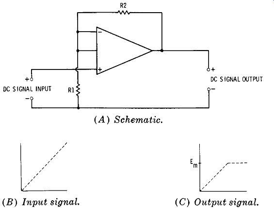
Fig. 9. Control amplifier-limiter.
9. CONTROL AMPLIFIER-LIMITER
The simple DC amplifier setup shown in Fig. 9A may be used as a limiting amplifier, provided the input-signal voltage rises high enough to overdrive the amplifier. Thus, the input-signal voltage may increase uniformly, as shown in Fig. 9B; but, in response, the output-signal voltage will rise uniformly (and at an amplified level), but will level off at level Em, as shown in Fig. 9C, when the amplifier reaches saturation. Any further increase in the input-signal voltage beyond this point results in no further increase in output voltage. The output signal thus is limited to the level Em.
In control systems, this sort of limiting is advantageous when a control signal regularly makes large excursions, but the circuit to which it is applied demands a constant value.
The IC-amplifier arrangement shown here has the advantage over passive devices, such as zener diodes, in this particular application, that it provides amplification and does not heavily load the signal source.
Any differential operational amplifier having the desired voltage output, gain, and impedance (resistance) characteristics might be used. The simple DC amplifier shown in Fig. 10, Section 2, is an example. It is necessary only that the selected unit, when operated with an available control signal, overload at output voltage level Em.
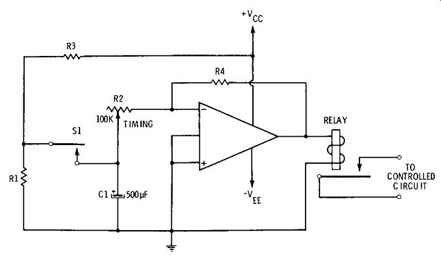
Fig. 10. Interval timer.
10. INTERVAL TIMER
Fig. 10 shows the circuit of a time-delay-relay type of interval timer. When push-button switch S1 is momentarily depressed, the relay closes and remains closed for an interval equal approximately to the time constant R2C1. Operation occurs in the following manner: When S1 is momentarily DC pressed, capacitor C1 is charged by a DC voltage derived from the voltage divider, R1-R3. This divider is proportioned so as to deliver approximately 1 volt from the supply Vcc·•
The release of S1 disconnects C1 from the charging voltage, but the capacitor retains its charge for a while, discharging slowly through R2 and the input resistance of the IC. When the capacitor voltage has fallen sufficiently, the current delivered to the relay will be too low to keep the re lay closed, and the latter consequently will open. The interval during which the relay remains closed is equal approximately to t = RC, where R is the resistance setting of the 100,000-ohm rheostat R2, and C is the capacitance of the 500-µF electrolytic capacitor C1. At the maximum-resistance setting of R2, the closure interval thus is 50 seconds. Longer intervals may be obtained with higher values of R2.
This setup may be used with any DC amplifier IC and milli ampere-type DC relay. (The circuit shown in Fig. 1 thus can be readily adapted by adding the timing subcircuit to the IC input in place of resistor R1 in Fig. 1.)