AMAZON multi-meters discounts AMAZON oscilloscope discounts
Overview
Plants that are implementing alarm and trip systems must follow the legislative and regulatory requirements in effect at the site. ANSI/ISA-84.01-1996, Application of Safety Instrumented Systems for the Process Industries provides detailed information on implementing critical trips for process applications, in particular where programmable electronic systems (PESs) are used as the logic function.
AMAZON multi-meters discounts AMAZON oscilloscope discounts
The purpose of a plant alarm system is to bring a malfunction to the attention of the opera tor(s), whereas a trip system takes protective or corrective action when a fault condition occurs. A plant trip system could shut down the process in an orderly fashion, or it could switch over from some defective unit (such as a pump) to a standby unit. In most cases, a trip system remains dormant and quite frequently unused until there is a demand on the system (or if it is being tested). Alarm and trip systems protect only when they work.
The reliability of alarm and trip systems is achieved through the following:
• Their fundamental design.
• The conditions under which they operate.
• The capabilities of properly trained plant personnel.
• The frequency at which they are tested.
Processes are generally provided with two trip systems. The first is a trip system for normal operation (commonly part of the control system) and typically related to production, quality, and financial issues. The second is a safety instrumented system (SIS) for handling critical trips. Additional categories can be generated to account for plant/process-related requirements.
Critical trips protect the safety and health of people, and in many cases also environmental areas, by taking the process to a safe state when predetermined conditions are violated.
These two systems-the normal control system and the SIS-should be physically separate to maintain their independence. This will increase their reliability and minimize the possibility that they both fail as a result of a common cause. Separation, which includes the power supply circuits, reduces the probability that both the control system and the SIS are unavailable at the same time or that changes to the control system affect the functionality of the SIS. Where possible, different types of measurement should be used for each system of control. For example, if a capacitive probe is used for level control, then, if appropriate, a bubbler may be used for the SIS. It is imperative to ensure, particularly for the SIS, that the sensors selected are appropriate for the application.
A SIS system is composed of the sensors, logic, and final elements that are required to take the process to a safe state. Since the failure of a SIS could harm the environment and, more importantly, lead to loss of life, it is incumbent upon the plant to ensure that the SISs (including their power supply system) function properly and reliably. Therefore, SISs must be regularly tested, and their design must allow for such testing. Bypassing or forcing any function of the SIS can only be allowed by procedures and, where possible, should be annunciated to the operator.
Once a SIS places a process in a safe state by tripping it, it must maintain the process in that safe state until the hazard is removed and a reset has been initiated. This reset function is typically a manual action by an operator. In addition, manual means that are independent of the logic should be provided to actuate the SIS's final elements if manual operator intervention is required.
Fail-Safe and Deenergize-to-Trip
All systems will fail sooner or later. A fail-safe system will go to a predetermined safe state in the event of a failure. In a deenergize-to-trip system, the outputs and devices are energized under normal operation; removing the power source (electricity, air) causes a trip action.
Where possible, it is preferable to implement all plant alarm and trip systems as fail-safe and deenergize-to-trip. For SISs in particular, implementing them as fail-safe and deenergize-to trip is strongly recommended. Fail-safe and deenergize-to-trip implementation may not be possible or suitable for an application because of the severe consequence of a nuisance trip. In these cases, additional safeguards are required to maintain the safety of the process when the SIS malfunctions.
Where possible, the design should ensure:
• that sensor failure or loss of electrical power or instrument air will activate the alarm or trip and go to a safe condition,
• that the initiating contacts energize to close during normal operation and deenergize to open when the alarm or trip condition occurs,
• that if a high process value is the trip condition, the sensor is reverse acting (i.e., a high value generates a low signal) so the trip occurs on the loss of signal,
• that solenoid valves are energized under normal operating conditions but deenergize to trip, and
• that pneumatically operated trip valves move to a safe trip position on air supply failure.
Safety Integrity Level
There are many types of integrity and criticality classifications which vary with the application. The process industries, have in general, adopted the Safety Integrity Level (per ANSI/ISA 84.01). The machinery industries and combustion systems have adopted different classifications and they will not be discussed in this book.
The safety integrity level (SIL) defines the level of performance that is needed to achieve a safety objective (see design section later on in this Section). The higher the SIL, the better the safety performance of the SIS and the more available the safety function of the SIS (see TABLE 1). Associated with the SIL is the "probability of failure on demand" (PFD). The desired SIL is met through a combination of design considerations. Two key considerations are separation and architecture.
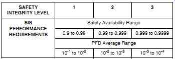
TABLE 1 Safety integrity level performance requirements.
Separation ensures that the process control system and SIS functions are independent so they don't fail from the same cause. For SIL1 applications, identical separation (i.e., each of the two systems uses similar equipment) is generally acceptable. However, diverse separation provides a more reliable system and is therefore recommended. For SIL2 applications, diverse separation is highly recommended, and for SIL3 applications diverse separation is generally required.
Where it is not possible to separate the SIS from the process control system (for example, in turbine control systems), additional considerations are required. These can include evaluating the failure of common components and their impact on the SIS, supporting the whole system as a SIS, and limiting access to the system to avoid tampering.
Separation should also be implemented at the design level. Preferably, the design team implementing the process control system should not be the same group implementing the SIS. This approach minimizes the effect of common mode faults from a design point of view.
Architecture that typically meets the SIL performance requirements are:
• For SIL1, a one-out-of-one architecture with a single sensor, single logic solver and a single final control element
• For SIL 2, more diagnostics than SIL 1 and may include redundancy for the sensors, logic solver, and/or final elements
• For SIL 3 applications, at least two separate, redundant, and diverse systems are required, each with its own sensor, logic solver, and final control element. Moreover, the two systems must be on a one-out-of-two ("1oo2") voting scheme. Sometimes three parallel systems are used with a two-out-of-three ("2oo3") voting arrangement.
The architecture a plant selects should in the end be based on the reliability of the system components and their test frequency.
Elements
A typical SIS consists of three basic elements: input, logic, and output. Other parts that have a potential impact on the safety function, such as power supply, are also considered part of the SIS (see FIG. 1). SISs require a dependable power supply, and quite often an online uninterruptible power supply (UPS) is added to ensure reliable operation. Deenergize-to-trip systems do not require electrical power to trip. They bring the process to a safe condition on power failure, and therefore, redundant power sources may not be required. However, they are required on energize-to-trip applications.
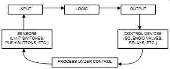
FIG. 1 Typical SIS elements.
The failure of sensors (switches, transmitters, etc.) and control devices (solenoid valves, control valves, etc.) account for the majority of SIS equipment failures.
Input
The input converts process variables into the digital form required by the logic unit. For analog signals this conversion includes comparing the input to a trip set point to obtain a status. Typical forms of inputs include self-contained discrete devices, such as limit switches and push buttons, or analog systems, which consist of a measuring element, a transmitter, a comparator, and a discrete output (see FIG. 2). Whenever possible, sensing elements should be installed in such a way that they can be tested without disconnecting wires or loosening pipe or tubing fittings. As an example, the impulse line between the process and a pressure switch may include a tee and a shutoff valve between the isolation valve and the sensing element (see FIG. 10). This is used to be able to inject an appropriate test signal. In addition, it is good practice to use switches that have hermetically sealed contacts to avoid corrosion and contact film, thereby improving reliability.
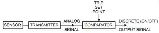
FIG. 2 Analog signal input to trip system.
In a system that is measuring levels, bouncing liquid levels may cause annoying alarms and trips. Introducing a few-second delay or dampening may solve this problem. When such time delays are employed, the designer should ensure that the delay is short enough that the process's safety time constraints are not violated. Also, where smart field devices are used, they should be write-protected and provided with read-only communication to prevent inadvertent modifications. In addition, if possible, calibration adjustments on the selected measuring instrument should be limited to prevent adjustments into the dangerous range. For example, if a trip point is set at 100 psig (700 Kpag) and the dangerous zone is reached at 150 psig (1050 Kpag), it would be prudent to select a pressure switch whose upper range is less than 150 psig (1050 Kpag). This would prevent an accidental setting at or above 150 psig (1050 Kpag).
If redundant sensors are used, they may be connected to both the process control system and the SIS, provided that the failure of the process control system will not affect the SIS's functionality. The reliability of SIS equipment is increased by using levels of redundancy and diversity in measuring sensors. Common-cause failures can be minimized by properly applying redundancy and diversity. For example, when using redundant sensors plants should use different principles of operation and different manufacturers and compare the outputs, alarming or shutting down on unacceptable deviations. In addition, the effectiveness of field devices can be enhanced by comparing two values, for example, flow measurement with the modulating valve position and analytical measurement with a basic measurement such as pressure and temperature.
Redundancy is applied to enhance safety integrity and improve fault tolerance. Redundant systems should be analyzed for common-mode faults such as plugging of shared process impulse lines, corrosion, hardware/software faults, and shared power sources. Diverse redundancy is recommended for SIS systems. However, redundancy should not be used where it will be a justification for using lower-reliability components.
Logic
The logic takes the input(s) and produces the output signal(s). The logic of a SIS must be designed with a manual reset function to prevent the process from initiating an automatic restart when power is restored or when the cause of the trip is removed. The three most common types of logic hardware are direct-wire systems, electromechanical relays, and programmable electronic systems (PESs). Other available types of logic are solid-state logic and motor-driven timers. The logic for a SIS can be implemented using any or a combination of these types. Generally, the latest technology is used to implement a process control system; however, SIS technology is typically implemented using a proven and mature product.
Direct-wire Systems
In direct-wire systems, the discrete sensor(s) is directly connected to the final control element.
This approach can be used only for the simplest applications.
Electromechanical Relays
The acceptance of electromechanical relays is now widespread. They are commonly used for SIS applications. Additional information on relays is provided in Section 9 in the section "Control Room Instrumentation." For SIS applications, some industries use safety relays. Such relays have many built-in features, such as mechanically interlocked contacts to ensure pre defined behavior. The contacts are interlinked by a mechanical bar that ensures that all normally open (NO) contacts do not close if the normally closed (NC) contacts do not open. If either the NO or NC contacts are welded shut, the mechanical bar will prevent the opposing contact from operating. A minimum contact set for a safety relay consists of one NO contact and one NC contact.
Where safety relays are not used, consider the following requirements:
• Use industrial quality relays.
• Contacts should open on coil deenergization or failure.
• The coil has gravity dropout or dual springs.
• Proper arc suppression is provided for inductive loads.
• Consider the need for a hardwired two-out-of-three (2oo3) voting logic (see FIG. 3).
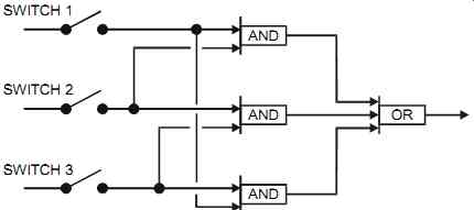
FIG. 3 Majority voting logic.
Programmable Electronic Systems (PESs)
PESs are used in SISs when there are large numbers of inputs and outputs, where the logic is complex, where communication with the SIS is required, and where different trip point settings are required for different stages of an operation (e.g., in a batch control system). Plants considering the use of a PES for SIS applications should weigh the fact that the PES's solid-state nature means its failure mode is unpredictable and could be unsafe. When PESs are used in SIS applications, they should:
1. Be approved for safety applications and implemented in compliance with the applicable codes.
2. Use extensive diagnostics and fault-tolerant architectures.
3. Use internal and external watchdog timers. The internal watchdog timer function is generally supplied within the PES. The limitations of the internal watchdog timer are that it may fail to monitor the complete application or it may fail for the same reason the PES fails.
The external watchdog timer monitors an input and an output and ensures that they are continually being scanned by the processor (see the subsection "Safety and System Failure" in the "Special Design Considerations" section of Section 9). Using an external watchdog timer does not eliminate the need for an internal watchdog timer. Some safety certified PESs do not require external watchdog timers because of their voting technology. PESs (see Section 9) can be more reliable than relays if they are implemented with the appropriate redundancy and diagnosis. For complex systems, PESs are usually easier to use than relays. In addition, they produce clear and comprehensive information (i.e., they will log activities), and they easily monitor any SIS overrides or defeats. However, typical PESs have an unpredictable failure mode and are therefore not used in critical applications unless they are approved for such applications.
PESs are more susceptible than relays to electrical noise, and they can easily be modified with out record update (creating an uncertain condition). Hardware and software modifications to PESs should be carefully controlled and their effects carefully studied. They should be implemented only by trained personnel. Where possible, alternate means, such as emergency shut down push buttons wired directly to the output devices, are provided to the operator to bring the process to a safe state if the PES malfunctions.
Output
The output converts the results from the logic into one or more process variables. Typical forms of output devices include solenoid valves, trip relays, and the like. Most output devices should deenergize to trip. That is, a motor should stop on the loss of control signals, and a valve should fail in the safe process condition when the signal or power supply (electrical or air) fails. Users should carefully study the failure mode of output devices. Both signal and power failure must be taken into account as well as the behavior of output devices when signal or power suddenly resumes.
Users should consider the following points for control valves in SIS applications:
• The opening and closing speeds. They should ensure that these speeds match the process requirements.
• After long periods in the same position (opened or closed), an on-off valve may become stuck in a certain position. Therefore, where applicable, a modulating control valve may be desirable since its continuous operation confirms that the valve is operational. A safety review should be performed to assess the dual use of a modulating control valve for pro cess control and for SIS. This dual functionality can be used for SIL 1 and 2 only. SIL 3 requires a separate trip valve(s).
• The need for valve position feedback to confirm the trip action.
• Where solenoid valves are used, the solenoid should be mounted between the positioner and the actuator. This approach bypasses the effect of a malfunctioning positioner.
In environments where leakage from a closed automatic trip valve may cause a dangerous condition, plants should implement double-block-and-bleed valves. Double-block-and-bleed valves consist of two valves in series with a bleed/vent valve between the two valves (see figure 1 in Section 3). If the process fluid leaks through the first block valve, it will bleed or vent instead of going through the second block valve and into the process.
Design
A good design must consider the failure of alarms and trip systems and propose the simplest system that will meet the application's requirements. The equipment selected must be of good industrial quality and must operate under conditions well below its maximum limits.
Where appropriate, it is good practice to use prewarning alarms. These notify the operator before the trip point is reached triggering the shutdown. Especially in today's modern control systems, prewarning alarms can be easily implemented at a minimum cost.
The design should also reflect that common points (junction boxes, cable runs, etc.) are protected from outside hazards such as fire, heat sources, and the like. Common-cause failures can be caused by design errors, environmental over-stress (high/low temperature, pressure, vibration, etc.), single elements (common process taps, single energy sources, single field devices, etc.), process conditions (corrosion, fouling, etc.), and poor maintenance or operation (procedures, training, etc.). These common-cause failures must be closely assessed during the design stage and throughout the life cycle of the SIS.
To maintain the functionality of SISs and the safety of the plant, the designer should be very careful about implementing trip bypasses or, better still, avoid them. If they are implemented, they should be automatically reset by timers or be alarmed on a set frequency.
The design of SISs typically involves one of two methods: qualitative or quantitative.
Qualitative
In the qualitative approach, the design is based on the application of good engineering judgment, relative knowledge of the process risks, and experience. This method uses a series of company-dependent qualitative matrices. First, the severity of the consequences of process failure is determined (see TABLE 2). Then, the likelihood of occurrence is determined (see TABLE 3). Tables 2 and 3 show five occurrence likelihood levels each. The severity and likelihood of occurrence are then combined to assess the risk level (low, medium, or high), thereby determining the SIL levels (see TABLE 4). TABLE 2 Risk severity: Example.
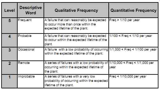
TABLE 3 Risk frequency: Example.
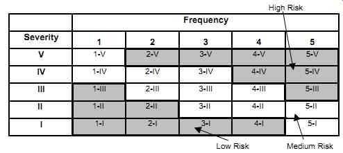
TABLE 4 Overall risk: Example.
The next stage is to evaluate the effectiveness of the protection layers, other than the SIS under consideration. Using these qualitative evaluations, an SIL number is determined. The more layers, the lower the SIL required (see FIG. 4). Then, by following a company-set guide line (see FIG. 5), the process designers implement a design. For example, if a "serious" severity is selected with an "occasional" frequency, the overall risk is "medium." With only one layer of protection an SIL 2 is required, whereas with an extra protection layer an SIL 1 will meet the requirements.
Quantitative
In the quantitative approach, the design is based on numerical data and mathematical analysis.
The SIS responds to a demand from the process and protects the plant from hazards. Since all components of a SIS are subject to the probability of failure, such failures may result in a hazardous condition. If the SIS is not functional, a demand from the process may result in a hazardous condition.
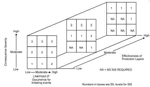
FIG. 4 Qualitative matrix: Example.
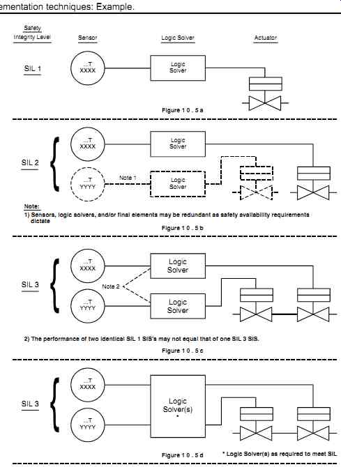
FIG. 5 SIL implementation techniques: Example.
Without a SIS in place to prevent the hazard, the hazard rate equals the demand rate. In other words, a hazard may take place every time the conditions that would have activated a SIS occur. Typically, a SIS is down, that is, non-operational (and therefore not available) for only a relatively short time, known as the probability of failure on demand (also sometimes referred to as the "fractional dead time"). System availability is the probability that the SIS will effectively respond to a demand:
SIS availability = [1 - (hazard rate / demand rate)] x 100 Probability of Failure on Demand (PFD) = Hazard rate / Demand rate = H / D
Typically, the demand rate is more frequent than the acceptable hazard rate. It should be mentioned at this point that a SIS is not required if D is less frequent than H, i.e., if the potential occurrence of a hazard is less frequent than the acceptable hazardous event rate. For example, if an environmental release is considered acceptable at a certain rate (say H = 0.01)-and at the same time, and due to non-instrumented layers, a demand can only occur at a lower rate (say 0.001)-then a SIS is not required.
For a simple one-out-of-one trip system,
PFD = Fd x T/2 (see FIG. 6) which means: H = D x Fd x T/2
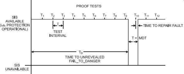
FIG. 6 System availability with regular testing.
The hazardous event rate (H) is a small fractional number that represents the frequency at which a hazardous event may take place, expressed in occasions/year. This low value is specified by plant management (and generally not by the SIS designer). It is based on regulations, insurance guidelines, industry standards, and corporate guidelines.
Demand rate (D) is the frequency at which the SIS is required to perform, expressed in occasions/year. It is the frequency of a potentially hazardous event that would have occurred if the SIS was not providing protection.
Failure rate (F) is the rate at which the SIS develops a failure and becomes inoperative. The dangerous failures are the fail-to-danger (Fd), since the fail-to-safety (Fs) will reveal them selves and bring the process to a safe condition. Depending on the equipment used and on the application, the failure rate (F) of a SIS component may always fail-to-danger (Fd) or may never fail-to-danger (i.e., always fail in a safe mode). Some users have set a ratio of Fd to F (such as Fd = F / 3), while some others rely on collected data or other sources of information. F values are available from references, from compiled plant data, and from published references such as Guidelines for Process Equipment Reliability Data (Center for Chemical Process Safety / American Institute of Chemical Engineers, 1989) and Offshore Reliability Data (Det Norske Veritas, DNV Technica, 3d ed., 1997).
Test interval (T) is the time between tests. To be effective, T must be a lot less than the demand (D) on the system. On average, a failure occurs halfway between two tests; in other words, a component will be dead for T/2.
The five most commonly used equations are as follows:
1. For simple 1oo1 (one-out-of-one) trips H / D = PFD = 0.5 x Fd x T For example, if a SIS for environmental safety management consists of a pressure switch, relay, solenoid valve, and shutdown valve (see FIG. 7), then by adding each component's Fd rate:
0.03 + 0.02 + 0.03 +0.03 = Fd total = 0.11
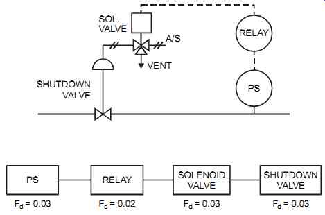
FIG. 7 Simple trip system.
If T = twice a year = 6/12 = 0.5 yr, then PFD = 0.5 x 0.11 x 0.5 = 0.0275 and that meets SIL 1 (which is 0.1 to 0.01).
With D = once every 2 years = 0.5 / yr H = D x PFD = 0.5 x 0.0275 = 0.01375/ yr
Or, once every seventy-three years. That is, it is expected that this SIS will fail on demand once every seventy-three years, releasing contaminants into the environment. This calculated hazard rate (H) should be compared with the hazard rate set by management.
It is not essential to test all the elements of a SIS at the same time. An average PFD can be calculated for different test frequencies, where;
PFD = 0.5 x [(Fdsensor x Tsensor) + (Fdlogic x Tlogic) + (Fdvalve x Tvalve)] If, to improve the PFD, two components within a SIS are redundant, then the following 1oo2 equation should apply for these redundant components. This would apply to two switches in series where either one can trigger the trip logic or to two shutdown valves where either valve can trip the process. These redundant components should not have the potential of a common mode failure.
2. For 1oo2 (one-out-of-two) trips, that is, two parallel/redundant trips PFD = (Fd² x T²)/3
3. For 2oo2 (two-out-of-two) PFD = Fd x T
4. For 2oo3 (two-out-of-three) trips PFD = Fd² x T² In industrial applications, 2oo3 logic provides a compromise between improved safety and reduced nuisance trips. For hardwired systems, this can be implemented as shown in FIG. 3.
5. For 2oo4 (two-out-of-four) PFD = Fd3 x T3
For other configurations, different equations apply.
Documentation
Good documentation begins at the design stage and continues through the commissioning, startup, and lifetime of a plant. During design, the hazards that require alarms or trips should be identified in the design notes, in the hazard analysis studies, and in drawings such as inter lock diagrams and logic diagrams. SISs, in particular, should be clearly identified and should be kept up to date as the system evolves. The documentation of SIS should be under the control of a formal revision and release control program.
SIS implementation requires supporting documentation, such as the following examples:
• Safety requirement specifications
• A description of the logic (see FIG. 8 for a typical description)
• Design documentation, including quantitative or qualitative verification that the SIS meets the SIL
• A commissioning pre-startup acceptance test procedure
• SIS operating procedures
• Functional test procedures and maintenance procedures
• Management-of-change documentation
The plant should prepare the safety requirement specifications to identify both the functional and integrity requirements. These documents are needed for design activities, for normal plant operation, and for testing purposes. In most cases, safety requirement specifications are also incorporated into the plant operating manuals to provide quick and clear information to plant operating personnel the moment they need it. On very small applications, the SIS safety requirement specifications could be part of the logic diagrams (an example of a typical logic diagram is shown in FIG. 9).
The content of a typical safety requirement specifications encompasses the following:
• The definition of the safe state of the process for each of the identified events.
• The process inputs to the SIS and their trip points.
• The normal operating range of the process variables and their operating limits.
• The process outputs from the SIS and their actions.
• The functional relationship between the inputs, logic, and outputs.
• Selection of deenergized-to-trip or energized-to-trip (with the former the recommended method).
• Considerations for performing manual shutdown.
• Actions to be taken when the energy sources to the SIS are lost.
• Response time requirements for the SIS to bring the process to a safe state.
• The response action to any self-revealing faults.
• Operator interface requirements.
• Reset functions. A reset function is required in order for SIS systems to prevent an automatic restart once the process conditions have returned to normal. An operator intervention through the reset function ensures a safe condition before process restart.
• The required SIL for each safety function.
• The diagnostic, maintenance, and testing requirements to achieve the required SIL.
• Reliability requirements, where spurious trips may be hazardous.
Testing
Every alarm and trip system will fail sooner or later. The primary purpose of testing is to uncover faults, and thus this activity is of prime importance in SIS applications. Testing should reveal all relevant faults, such as wear that prevents tight shutoff of a control valve or a plugged process isolation valve. According to its logic, a SIS must act when a hazardous condition is sensed. Therefore, the measurement, logic, and final element must all be functional-hence, all three components must be tested at regularly scheduled intervals.
The testing of SISs and the appropriate methods and equipment needed for testing should be considered at the design stage. The design documentation should provide a clear explanation of the intended method of testing and the assumptions on which the test method is based. The testing of SISs should, where possible, be designed to reveal all faults.
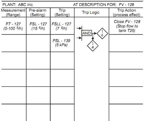
FIG. 8 Logic description.
The reliability of SISs is determined first through their fundamental design, then through the conditions under which they operate in the plant, and finally through the frequency by which they are tested. Sensors may be switches or transmitters. Switches are more direct, but they give no indication that they are functional. A transmitter, on the other hand, due to its continuous output is more likely to draw attention to its failure. Therefore, switches may require more frequent testing than transmitters.
Redundancy reduces the test frequency because the signals are valid as long as the two (or more) signals are identical. Diverse redundancy is preferred, for example, a pressure sensor backed up by a temperature sensor, both of which monitor the thermodynamic properties of a process.
Testing consists of creating an abnormal condition at the measurement point, observing the reaction of the final element, and ensuring that the logic has responded as expected. Testing should be done, where possible, using artificially generated process signals, since this checks the functionality of the SIS starting at the measuring element.
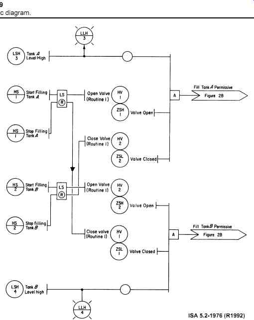
FIG. 9 Typical logic diagram.
When the failure of a SIS causes a spurious alarm or trip, it is said to be "fail-safe" or "fail-to-safety." This is because its failure shuts the process down to a safe state and draws attention to its malfunction. If, however, a fault occurs that does not reveal itself, then when the system is called upon to alarm or trip, no alarm or trip will occur, and a sometimes dangerous occurrence may follow. Such faults are called "fail-to-danger." If a "fail-to-danger" fault occurs, the affected system will remain in a risk condition until the failure is revealed and corrected. A fail-to-danger fault may be revealed either by the system's failure to operate when required (an unwanted and hazardous condition in most cases) or by testing (obviously the preferred method). Testing procedures should be, where possible, a simple and straightforward activity. Difficult and troublesome testing activities are quite often poorly performed or just ignored, which compromises the integrity of the SIS. SISs should be tested with minimal disturbance to the plant. The choice is between off-line testing, online testing- the two most common-and shutdown.
Off-line testing is performed while the process is off line, that is, not in operation. Off-line testing is the most common type of SIS testing. It has its limitations because scheduled shutdowns or turnarounds tend to be infrequent, of short duration, and very hectic, with the maintenance staff concentrating on scheduled repairs and readying equipment for production. Off-line testing is used before putting the SIS in service for the first time to confirm that the installed SIS meets the design requirements. The more frequent practice is to implement adequate testing during routine shutdowns.
Off-line testing must prove that the SIS can work under the required process conditions (e.g., at temperatures and pressures that will prevail when the plant must alarm or trip). This may be difficult if extreme conditions must be simulated by maintenance personnel, such as very high temperatures or pressures. Off-line testing may be an expensive proposition if the period between tests is shorter than the operating cycle. Therefore, SIS testing while the process is "on line" is sometimes required.
Online testing is performed while the process is on line, that is, operational. Online testing must be done under close supervision and in close cooperation with the operator. Great care must be exercised during online testing to avoid shutting down the plant by mistake. Even then, online testing is confined to those trips that can be defeated for a period of time without undue risk.
During online testing, the operator should monitor the incoming data from the sensor(s) and be ready to manually shut down if the process deviates beyond a known limit, that is, a real demand on the now isolated SIS. Therefore, provisions must be in place for the operator's safe manual intervention should a genuine emergency arise while the testing is being performed.
Online testing of the final control elements is very difficult and must be carefully planned. A full test of a final control element can only be done at process shutdown, unless redundancy of that element is implemented. If it is, then procedures must be in place to ensure that the SIS with its redundant systems goes back on line when the testing is done. In critical cases, redundant output components, such as trip valves, are used. These allow one component to be tested while the other is fully functional. In some other cases, plants implement complete redundant SISs to pro vide very high reliabilities and to allow the full online testing of a SIS while the process is maintained under another SIS. Shutdown testing is a form of online testing. Here, the testing of the trip actually shuts down the process. This type of trip is seldom used, except for batch systems, where the cycle frequency is relatively short. Shutdown trips do test the complete system and are usually done by (or under the guidance of) the operator. Shutdown testing intentionally brings the process to the actual trip condition to observe how the SIS responds. This method, if used, should be care fully evaluated before it is implemented, should be performed under controlled conditions, and should be avoided if it puts the whole process at risk.
After SIS equipment has been tested and repaired, it is a good and safe practice to have a second person inspect and approve the completed work. Also, the equipment operator must always be advised of (and agree to) an upcoming test.
Methods
SISs can be tested by breaking down the system into its three main elements (input, logic, and output) and testing them individually. Although the different elements can be tested at different intervals, a complete functional test of all elements as one unit should be done at a preset interval, for example, when the plant is shut down.
Inputs are tested by finding out if they respond correctly to a simulated or a real change in pro cess conditions. The methods of testing in order of preference are as follows:
1. Isolating the impulse line to the measuring sensor, after closing the isolation valve, and injecting a simulated signal (while testing, the trip set point should be verified). See FIG. 10.
2. Altering the set point to cause a trip.
3. Altering the switch or transmitter output by altering its range or zero point.
Logic systems are tested by simulating action at the input and verifying that the output(s) respond correctly. This may require the use of defeat or bypass switches to enable section-by section testing. When defeat or bypass switches are activated, an alarm in the plant control sys tem should remind the operator at a set frequency (say, every hour) that the switch has not been reset yet. Logic testing should be done off line (where possible); online logic testing is difficult and may trip the plant.
Outputs are tested by finding out if they respond correctly to a simulated or a real command from the logic. The most common output devices for trip functions are motors and trip valves.
Testing motors is a simple start/stop activity. Testing trip valves requires careful planning since a trip valve may also be a modulating control valve. The most common methods for testing valve-based trips, in order of preference, are as follows:
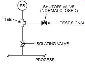
FIG. 10 Pressure sensor testing facility.
1. Allowing a valve to trip
2. Using a chock (a travel-limiting device) to limit valve movement and allow the valve to trip to chock
3. Injecting a suitable signal into the solenoid valve vent to control the movement of the main valve
4. Bypassing the action of the trip solenoid valve
Frequency
How often SISs should be tested is determined by codes and regulations, by the importance of a particular system to personnel safety or plant performance, by the calculations that were used to determine the required safety integrity level (in a quantified approach), and by the results of previous testing. In addition, testing must be done whenever changes are made to the SIS and also after the SIS has been down for an extended time. The reasons behind the plant's test frequency should be carefully recorded. In certain cases, the testing frequency may have to be modified, for example, where the process is harsher on the sensors and final elements than originally thought.
When the frequency of testing is modified, all the modifications and reasons behind them should be carefully recorded.
As a starting point and in the absence of data, SIS testing can be set at a six- to twelve-month interval (but should not extend longer than once every three years). Analyzers are an exception and may need to be tested once per week, and sometimes once a day, depending on the analyzer and the expected accuracy. Sensors and control valves have the highest probability of failure. Therefore, the logic typically needs to be tested less frequently than the field devices that are facing the process conditions (see FIG. 11).
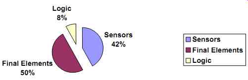
FIG. 11 Typical breakdown of SIS failures.
Too much testing reduces availability and increases the probability that undetected human errors will be introduced. Insufficient testing reduces SIS reliability. A balanced approach is important. Where some plant production units run for long periods of time, their SISs must be tested while the plant is running. This is typically done without interrupting the process. Such online testing requirements should be considered at the detailed design stage. The SISs for pro cesses that shut down relatively frequently can be tested off line.
Deferring a scheduled test to a later date is permissible either because the process is down or because the process shutdown is scheduled "shortly" after the SIS test is due. "Shortly" means when acceptable to safety, as determined through quantified data analysis, and typically within three months.
Procedures
Test procedures verify the operation and speed of response of all SIS components (including the logic sequence), the operation of all alarms, and the operation of the manual trips and sys tem reset.
Test procedures must not jeopardize the safety of maintenance personnel or personnel of the production facilities. When implementing a test procedure, the designer should determine if such testing will reveal all possible faults, such as wear that prevents tight shutoff or plugged pro cess isolation valves. The tests should be designed to minimize the risk of spurious trips and to allow safe manual overrides to intervene when plant emergency conditions develop during testing. The SIS test procedure is generally worked out and agreed upon by the various responsible persons in the plant and must be kept up to date. A test procedure is recommended for every alarm and trip in the plant, but is essential for all SISs.
A plant's process for preparing, reviewing, and approving the SIS test procedure should consider the following factors: the SIS test frequency, hazards to personnel and to equipment, reference information such as drawings and specifications, and the equipment and personnel who must do the testing. A simplified example of a completed SIS test procedure is shown in FIG. 12.
The following information should be indicated in the test procedure:
• Frequency of alarm/trip test
• Hazards to personnel and to equipment, required protection, and list of safety functions
• Reference information (i.e., drawings, specifications, etc.)
• Required test equipment and personnel
• Testing procedures
• Description and location of equipment to be tested
• Logic description
• Acceptable performance limits (e.g., +/- 2% of expected reading), where applicable
• The state of the process when the test is performed
The results of SIS testing and the corrective actions (where needed) are recorded on a document that is generally cross-referenced to the SIS description and the SIS test procedure. The document is completed by the person doing the testing and checked by a person responsible for SIS testing in the plant. This document should be available for future reviews, plant audits, or investigations should plant problems occur.
[Fig. coming soon] FIG. 12 Typical test procedure.
SIS test results typically show the following:
• The date of the test/inspection
• The name of the person(s) who performed the test/inspection
• The identification of the system (i.e., tag numbers)
• A description of the test/inspection to be performed and the identification of tested equipment
• The results of the test/inspection (both as-found and as-left conditions)
• Proof that the test/inspection was carried out
• A record showing the deficiencies and the required corrective actions
• A record to be used when reviewing testing frequency
• Confirmation that the SIS is operational after testing
Commissioning and Pre-startup
Commissioning encompasses the checking of installation and wiring work. An installation check confirms:
• that all temporary supports, connections, and the like are removed,
• that impulse and air line tubing installations are properly routed and supported,
• that all instruments are installed correctly,
• that tagging and nameplate details are correct and details match the corresponding specification sheet,
• that pressure testing for tubing is successfully completed, and
• that regulator pressures and purge flows are correctly set.
A wiring check confirms:
• that wiring is correct (through a continuity test),
• that power supply sources are operational and set per specifications,
• that grounding is implemented correctly, and
• that all SIS components and energy sources are operational.
Other checks confirm that:
• all instruments are properly calibrated.
• all loops are functional.
• all documentation is available.
The pre-startup acceptance test (PSAT) ensures that the SIS as installed conforms with the design before hazards are introduced. Records must be kept to substantiate that the PSAT is completed. The PSAT confirms that:
• all SIS components and links to other systems perform according to the design.
• safety devices are tripped at the defined set points.
• the proper shutdown sequence is activated.
• alarms are correctly displayed.
• the reset functions are operational.
• bypass functions and manual shutdowns operate correctly.
• all documentation (including test procedures) are consistent with the design and installation.
Management of Change
A written management-of-change procedure must be implemented to initiate, document, review, and approve all changes to the SIS other than replacement in kind. The review process must include personnel from appropriate disciplines including ownership (typically, operations), knowledge (typically, process and instrumentation engineers), and maintenance. In addition, the review stage of the change must ensure that the safety integrity of the SIS is maintained.
The management of change ensures that the following factors are considered before any change:
• The technical basis for the proposed change
• The impact of change on safety and health
• Modifications for operating procedures
• The time period needed for the change
• Authorization requirements for the proposed change
• Where applicable, the availability of memory space
• The effect of the change on response time
• Online versus off-line change, and the risks involved