AMAZON multi-meters discounts AMAZON oscilloscope discounts
Overview
The majority of modern control systems today are programmable electronic systems (PESs).
They are typically supplied with display systems, printers, and communication links. PESs include the following systems:
• direct digital control (DDC)
• distributed control systems (DCSs)
• programmable controllers (PLCs) and personal computers (PCs)
• microprocessor-based standalone PID controllers
Before the introduction of PESs, standalone indicators, controllers, recorders, annunciators, and the like were used for monitoring and control. Such standalone devices are still used for small applications, but for large applications they would be expensive and relatively difficult to modify. In addition, these standalone devices have limited features that are not acceptable in today's control requirements, take up a large amount of space in the control room, and have limit capacity for field-to-control room data exchange.
AMAZON multi-meters discounts AMAZON oscilloscope discounts
When implementing PESs, plant personnel should always keep the following key items in mind:
1. The simplest solution that meets the project requirements is generally the best approach.
2. The operator, who is really the end user, should be involved from the time the equipment is selected, through the design and implementation phases, and including graphics design and color selection. In addition, the operator must be well trained in how to use the system.
3. A successful implementation depends crucially on the quality of engineering and equipment.
Components
A PES is made of hardware and software. The hardware consists of input modules (accepting analog, discrete, or digital signals), control modules (which perform the logic), output modules (which send out analog, discrete, or digital signals), communication components, and operator interfaces (see FIG. 1).
• Input modules sense the process conditions and feed their own outputs to the control modules (see FIG. 2).
• Control modules form the computer portion of the PES and provide the data processing, logic, PID, and mathematical capabilities to meet the functional intent of the PES. The main components of the control modules are the processor and memory. The memory is classified as either volatile or non-volatile. Volatile memory will lose its content (the pro gram) when power is lost unless it is supported by a battery backup.
• Output modules are the inverse of input modules. They translate the signals from the control modules into the process by generating signals that are fed to control valves, stepper motors, and so on (see FIG. 3). An electric fuse is typically provided on all output circuits for protection. Discrete outputs are available as a dry contact or as a solid state. In the off mode, solid-state devices will generate an off-state current that is also known as "leak age current." Plant personnel should assess whether this leakage current is acceptable for the circuits.
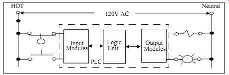
FIG. 1 Simplified diagram of a PLC.
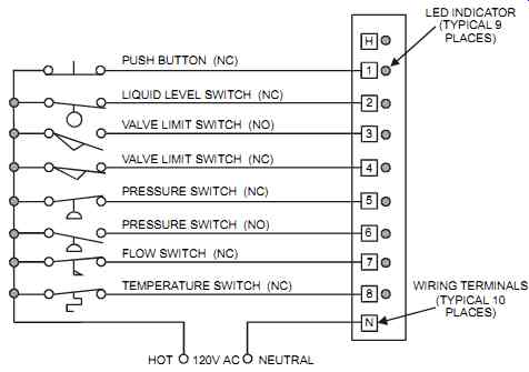
FIG. 2 Typical discrete input module.
• Communication links the components of a PES. A communication port is required at each component, and data is transmitted from port to port according to a protocol. The link between ports is established through networks, of which there are many available types.
For extra reliability, plants should consider communication redundancy (the two communication links should, where possible, be routed separately).
• The operator interfaces provide a window into the process so the operator can view the information inside the PES through various formats such as graphics, alarms, and historical trends. It is good practice to ensure that this interface is available at all times. There fore, the plant should consider installing a minimum of two operator interfaces functioning in full redundancy, even for a simple control system.
The software of a PES consists of two main parts: operating software and application software.
The operating software is fixed by the system vendor and cannot generally be accessed or changed by the user. The application software is implemented by the user to meet the project's requirements. Built-in capabilities, set by the system vendor and known as "firmware," may include input/output signal linearization, digitizing of analog signals, out-of-range signal detection, open input circuit, etc. These capabilities are available on most systems.
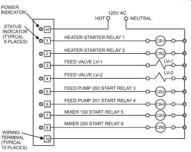
FIG. 3 Typical discrete output module.
A PES is a relatively small and economical device that can handle very complex applications at high speed. When selecting a PES, the choice should be based on functional capabilities, such as the following:
• General capabilities of the processor unit and memory (including data processing speed).
• The variety of inputs/outputs and number of points per module.
• Networking and communication capabilities.
• Modularity and ease of expansion.
• Operator devices and peripherals.
• Reliability, failure options, and redundancy capabilities.
• Programming and configuration requirements.
• Ease of repair and diagnostic capabilities.
• Environmental conditions sustainable by the PES.
• Manufacturer's service network, control experience, and financial health.
The user should understand well the options available, since they determine whether the PES will meet the plant's future needs.
Centralized Control versus Distributed Control
Modern industrial controls can broadly be categorized into two types: centralized and distributed controls. The location of the system's processing power defines which of the two categories a control system belongs to. Quite often, a plant will implement a combination of the two types to meet its requirements.
Centralized Control
Centralized control, also known as direct digital control (DDC), was introduced in the early 1960s. These systems were relatively slow, had limited memory, required complex programming techniques, and were not very reliable. Centralized control consists of a mainframe, a minicomputer, or a microcomputer to which are connected remote or local I/Os. In this architecture, all control functions as well as the operator interface are centrally located (see figure 4). Modern centralized control provides the most powerful and most flexible control systems by providing plants with custom control strategies to closely meet their requirements. How ever, the centralized control architecture may require specialized computer personnel, resulting in high implementation and maintenance costs. It also requires a clean control room environment.
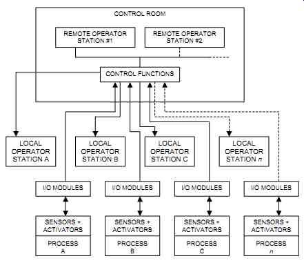
FIG. 4 Typical centralized controls.
Improvements in PC reliability (both in terms of hardware and software) and the availability of off-the-shelf software have started a trend toward using PCs as the controlling platform, marking a return to centralized controls. Many industries are now switching to this new approach, while others are waiting to see if PC-based control systems are as reliable as the well-proven distributed controls.
Distributed Control
Distributed control remains a strong trend at the moment. This type of control was introduced in the mid-1970s to solve the problems of centralized controls. In this architecture, the control and input/output functions can be close to the process while the operator interface is located in a remote control room (see FIG. 5). The hardware can be concentrated in one area or have its components spread throughout the process areas. Typically, distributed controls are one of two types: Distributed Control Systems (DCSs) or Programmable Logic Controllers with Personal Computers (PLCs/PCs). Sometimes, both PLCs and DCSs are used together in the same plant control system. Computers and standalone PID controllers operating in tandem are also considered distributed controls when the PCs act as supervisors and standalone PID controllers control the process.
DCSs are relatively easy to implement. They can be configured simply without complex programming, and their configuration is well documented. (Configuration means completing vendor-developed pre-set tables, while programming involves writing lines of code.) However, the costs of DCSs are relatively high (compared to PLCs/PCs), DCSs require specialized sup port, and the simple configuration sometimes results in limited functionality. Moreover, DCSs typically require a reasonably clean control room environment, and the user is commonly tied up to a specific vendor.
PLCs/PCs are relatively low in cost, easy to maintain, and comparatively fast. They have a versatile line of I/Os and can be mastered by maintenance personnel in a relatively short time.
However, PLCs/PCs typically require separate suppliers for the hardware and software and may present difficulties when implementing advanced control strategies. Moreover, creating two databases (one in the PLC and one in the PC) leads to errors. When implementing PLC/PC systems, the plant must establish the line of functional demarcation between the PLCs and PCs from the beginning. Typically, PLCs are used for process control and data collection, whereas PCs are used for PLC programming, documentation, and operator interface. With this functional-split philosophy, if the PC or its link fails the process is still under control.
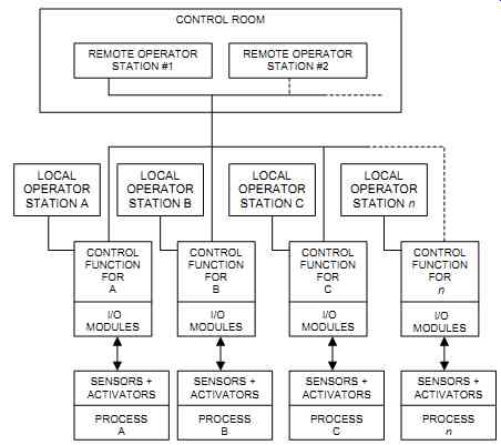
FIG. 5 Typical distributed controls.
Control Room Instrumentation
Traditional control room instrumentation and control devices consist of controllers, relays, recorders, and annunciators in addition to the simple indicators, pushbuttons, and lights.
Though this traditional instrumentation has now been replaced by computer-based systems, it is still in use in old control systems and in small applications.
Controllers
Controllers evolved in the past fifty years from simple three-mode pneumatic controllers to powerful stand-alone units (see FIG. 6). The performance of the controller depends largely on the stability of the process, good-quality control equipment, and well-tuned control parameters (see the section "Controller Tuning" in Section 8). Controller indication generally takes the form of direct-reading scales that express output in engineering units for the process variable (PV) and the set point (SP). The controller's output (OUT) typically has a 0-100 percent scale. Level instruments normally indicate their PV and SP in a 0-100 percent range. The scale range is normally greater than the operating range. For example, if the process has an operating range of 0 to 70, then a 0-100 scale is required. Typically, the closest standard scale range is used.
Typically, the auto-to-manual (A/M) transfer function is available as a standard feature on electronic controllers. However, plants should tightly control the use of A/M transfer, and remaining in manual should be a temporary condition. When controllers are left in manual mode because "that's the only way this loop will work," the plant should recognize that a fix is needed either in the field devices or at the controller. In addition, all controllers that have remote set point (RSP) are equipped with a set-point transfer function that permits bumpless transfer between local and remote.
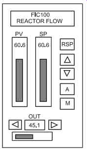
FIG. 6 Typical electronic controller faceplate.
Typical standard controller capabilities include the following:
• Ability to manually drive the output signal when the controller is in the Manual mode.
• Communication to a PC should be within the capabilities of the selected controller, and the required communication software should be available as an off-the-shelf item.
• Built-in alarm annunciation is generally available in the form of front-mounted LED lights.
• Power to two-wire transmitters.
• Programming must be simple to understand and apply (however, training may be required).
• Configuration must be retained on power loss.
• The controller should be secure from tampering.
Relays
An electromechanical relay consists of an electrically operated solenoid in which a magnetic field is produced and mechanical contacts are used to make or break electrical circuits (see FIG. 7). When the coil is energized, the resulting magnetic force causes a mechanical movement that changes the status of the contacts. When the coil is deenergized, the contacts return to their "normal" status. This rapid movement occurs within 5 to 20 milliseconds after the coil is energized. Most relays used for industrial control systems are energized with either 120VAC or 24 VDC.
A contact that is open when it is deenergized (i.e., in its shelf condition) is called "normally open" (NO). If the contact is closed when it’s deenergized, it is called "normally closed" (NC).
Where an NO and an NC contact are combined into one set of contacts with a common termination for power, it is referred to as a "form C contact." In spite of the widespread use of PESs, relays are still in demand for motor control circuits, for "permanent" simple logic circuits, and for critical trips. Relays provide adequate and reliable functionality for simple safety-instrumented system (SIS) logic. Emergency circuits that are used to stop the operation are typically routed outside the PES through relays. When well sized, the failure mode of relays is predictable, and hazard assessment is a lot simpler to accomplish.
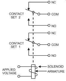
FIG. 7 Typical electrical relay with two sets of contacts.
With the proliferation of PLCs, the use of relays has dropped significantly. PLCs systems are preferable to relay systems because of their flexibility, reliability, and ease of implementation for complex logic and sequencing. Relays are a mature and simple-to-understand technology and are easy to troubleshoot. With a properly selected relay, the chance that the contacts will weld is remote. Relays have a "program" that is difficult to change (i.e., requires rewiring).
Relays have no memory integrity to worry about, and they will accept a wide range of operating temperature, moisture, corrosion, and vibration problems. In addition, relays are not sensitive to power problems, electrical noise (e.g., from walkie-talkies), poor grounding, or off-state leakage current on logic outputs. Also, relays have no program sequence problems (their logic is continuous and simultaneous), no need for additional protection such as master safety relays and watchdogs, and no need for specially trained personnel. However, relays are not suitable for complex logic, for analog measurements, and for applications that require diagnostics or reporting of the logic.
Relay contacts must be protected from excessive currents. Both the magnitude and the type of load must be considered. For example, a contact will not switch a 5 amp inductive load if it is only rated for a 5 amp resistive load, or if it is handling a device with an inrush current of 10 amp. Inductive loads require arc suppression because they create large instantaneous voltages (due to the building and the collapsing of magnetic fields). These arcs, if not suppressed, will harm the contacts. Arc suppression is typically required for DC circuits, whereas on AC circuits the arc is quenched when the alternating voltage passes through the zero point Recorders There are two main types of recorders: continuous trace (the conventional type) and digital (the microprocessor-based type). In continuous trace recorders, there should be a separate, non-clogging inking system for each pen, with sealed and replaceable ink cartridges. Preferably, the ink level in the cartridge should be visible when the door is open, and the ink cartridges should contain a four-month supply of ink. Also, cartridges should be fitted with means for starting the ink flow, and each pen circuit should be independent.
Digital recorders should typically display the point number that is being printed, and the descriptive data (date/time, scale range, messages) should be printed as the recorded value is being printed. These devices generally record points at a frequency of 6 sec./cycle or better and have self-diagnostics and math capabilities. Additional points plant personnel should consider are the need for averages or statistical functions, a connection between the recorder and a PC, and password protection.
For both recorder types, and depending on the process requirements, the chart scale should be linear, and the visible portion of the recorder should display at least eight hours of recording.
Similarly, there should be enough paper for 32 days, and alarm switches should be independently adjustable, covering 100 percent of scale. When specifying recorders, consider the types of inputs the application requires (mA, mV, A, V, T/C, RTD, etc.) and the need for attenuation, linearization, computation, and so on.
Annunciators--Annunciators are generally used to call attention to abnormal process conditions through individual illuminated displays and audible devices. The standard definition of an annunciator is an enclosure in which lamps are located behind labeled translucent windows. Each window is labeled to correspond to a particular monitored variable or status. Colored lights are sometimes used to uniquely identify some of the alarms on the annunciator.
Annunciators come in a variety of physical arrangements, operating sequences, and special features. Plants typically implement annunciator sequences in accordance with the ANSI/ISA 18.1-1979 (R2004), Annunciator Sequences and Specifications standard.
Annunciators are typically operated from electric contacts that are usually part of a field mounted sensing device. Two types of annunciator sequences are generally used, known as sequences A and M. The operation of each is different after process conditions return to normal.
Sequence A has an automatic reset (see FIG. 8). The sequence returns to the normal state automatically after the annunciated condition is acknowledged, when the process condition returns to normal. Sequence M has a manual reset. The sequence returns to the normal state after the annunciated condition is acknowledged, when the process condition returns to nor mal, and the reset push button is activated.
First-out annunciators are used to indicate which one of a group of alarm points is operated first. First-out sequences can be automatically reset or manually reset when alarms return to normal. Many methods for differentiating between first and subsequent alarms are used. Typically, when later alarms are activated, their visual displays do not flash, and their audible devices do not operate. The first-out indication is reset by pressing the Acknowledge button.
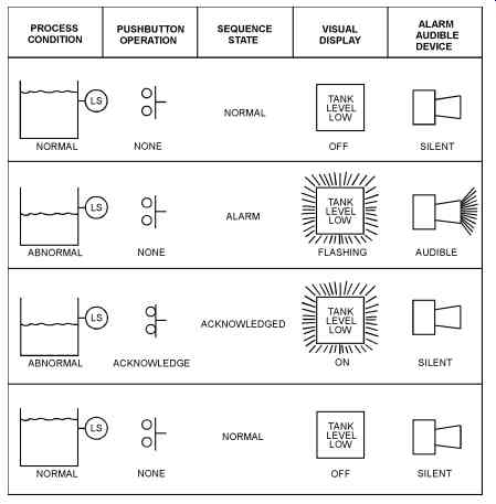
FIG. 8 Annunciator sequence A, with automatic reset.
Programming Languages
The International Electrotechnical Commission (IEC) is a sister organization of the International Standards Organization (ISO) based in Geneva, Switzerland. It has produced a standard that describes the five programming languages plants should use for industrial control systems.
The purpose of such a standard is:
• to provide a consistent method for programming
• to develop languages to encourage the development of quality software for solving different types of control problems
• to meet the needs of different applications and industries
IEC standard 61131 provides three graphical languages (functional block diagram, ladder diagram, and sequential function chart) and two textual languages (structured text and instruction list). These languages are vendor independent and portable, and can run on PESs from different vendors.
Functional Block Diagram
The functional block diagram depicts signal and data flow by using function blocks. A function block consists of a rectangle whose inputs enter from the left and whose outputs exit from the right, as on an electronic circuit diagram. The outputs of a block may be inputs to another block, with the signals going from left to right (however, some signals are fed back). The functional block diagram employs reusable software elements, describes the program as a set of interconnected graphical blocks, and is typically used where the program involves the flow of signals between blocks (see FIG. 9 and 10). The functional block diagram can be used within the ladder logic or the sequential function charts and typically includes the following common blocks:
• PID controller, on-off controller, ramp generator, totalizer
• Equal, greater than or equal, less than or equal, greater than, less than
• And, or, xor, not, latching relay, on delay, off delay, up counter, down counter
• Math functions (add, subtract, multiply, divide, square root, average)
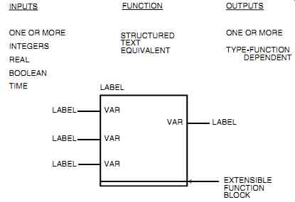
FIG. 9 Function blocks.
FIG. 10 "Soft-wiring" of function blocks.
Ladder Diagram
Ladder programming evolved from the electrical wiring diagrams used to describe relay logic.
It has a left-hand power rail that supplies "power" through software contacts along the horizontal rungs. Elements of the ladder logic provide connections between the power rails to software coils (see FIG. 11). The contacts represent the state of a Boolean variable. When all contacts in a rung are true, power will flow and operate a coil located on the right of the rung.
This programming language is typically used for logic involving AND, OR, and TIMER functions. Its graphical representation is easy to understand, can be learned relatively quickly, and is well accepted by maintenance personnel because it's similar to electrical wiring diagrams (see FIG. 12). Ladder programming clearly identifies the live state of contacts in the pro gram while it's running and therefore provides powerful online diagnostics. However, using this programming language makes it harder to break a complex program down (especially if a large program is written by different programmers) or to implement complex math. The typical ladder functions are as follows: contacts normally open (NO), contacts normally closed (NC), coils (retentive or non-retentive), and timers.
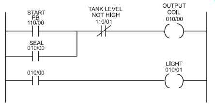
FIG. 11 Ladder logic diagram.
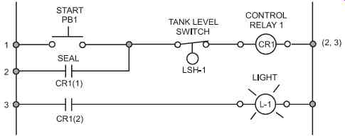
FIG. 12 Electrical wiring diagram.
Sequential Function Chart
The sequential function chart depicts the sequential behavior of logic (for time- and event driven sequences) and shows the main states of a program (see FIG. 13). It is used to represent a program's internal organization rather than being a true programming language. The sequential function chart is represented as a series of steps symbolized as rectangular boxes that are connected by vertical lines. Each step is a state of the system under control (with the initial step "Start"), each step is associated with one or more actions (each action has a unique name), and each connecting line has a horizontal bar that represents a transition (see FIG. 14). The flow of control is typically from top to bottom, with branches that are used for the flow to go back up. The sequential function chart can be used to partition a program; that is, each phase can be considered/executed separately.
Structured Text
Structured text resembles the Pascal programming language (see FIG. 15 and 16). It was specifically developed for industrial control. Structured text is very useful for stating equations. It can be written with meaningful identifiers/comments and is useful for complex mathematical calculations. However, in structured text there are limitations on the length of expressions, statements, and comments.
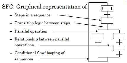
FIG. 13 Sequential function chart.
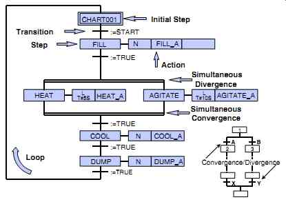
FIG. 14 Example of a sequential function chart.
=========
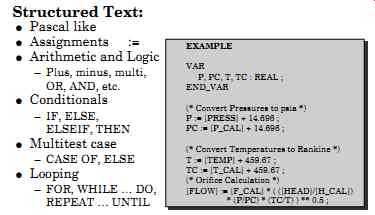
FIG. 15 Structured text
========
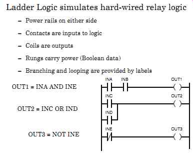
FIG. 16 Structured text compared to the same expression in ladder logic
Instruction List
The Instruction List is an assembly-like language and is not commonly used in the process industries.
Fieldbus
Fieldbus is a digital link that is starting to replace the conventional 4-20mA standard signal so familiar to industry. It connects several field devices in a multidrop network enabling these devices to share information (see FIG. 17, 18, and 19). Such a system offers tremendous economical benefits as well as operational advantages. Some large facilities have started implementing Fieldbus, and sooner or later every user will be facing the decision whether "to be or not to be Fieldbus." A control room operator familiar with DCSs or PC/PLC-based controls should have little difficulty migrating to Fieldbus systems.
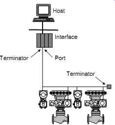
FIG. 17 Simple network with only one single element.
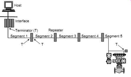
FIG. 18 Network with multiple series segments used for long distance.
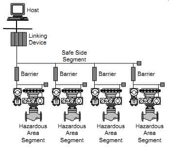
FIG. 19 Several hazardous-area segments connect to a safe-side segment
using repeating barriers forming a single network.
For the process industries there are three major Fieldbus systems on the market. They are Foundation Fieldbus (standardized by the ISA), Hart (which has been around for a while and is almost a true Fieldbus), and Profibus (a mainly European bus). The first two are the most common in North America, and each of the three has its pros and cons. This handbook will describe the first one only. Be very careful when you pick a Fieldbus system. You'll be stuck with it for a long time, so make sure it's the best one for your application. Additional information on the Fieldbus is available from the ISA-50.02 standards.
Fieldbus implementation has many benefits.
• Wiring (and labor) cost savings are greater than in conventional 4-20mA installation since Fieldbus does not require one-to-one wiring.
• Controlling can be done at the field device, which reduces the load on the "central" control system (i.e., faster control with smaller systems). This is a unique capability of Foundation Fieldbus.
• Non-proprietary programming means that once you learn it you've learned it for all systems.
• Fieldbus technologies work on the same type of wires as conventional instrumentation, which makes it easy to migrate from existing conventional systems to Fieldbus.
• Fieldbus offers very powerful diagnostics for field devices, which saves troubleshooting time and reduces commissioning and startup costs.
• Digital communication provides very high accuracies no longer limited by the 4-20 mA range. This applies to monitoring and controlling (see "Inputs and Outputs" in the following section "System Specification," in this Section).
• The control room can "write" to field devices, adjusting and changing calibration remotely (a function that can be write-protected).
• Individual field devices can measure and transmit more then one process variable. The savings from such multi-variable transmitters can be substantial.
Fieldbus implementation has also some drawbacks.
• If a network communication wire fails (a rare occurrence), the entire network fails. This takes down communication to many sensors and valves, and leaves the control room operator in total darkness. However, powerful diagnostics will immediately point to the failure. To avoid this, plants should consider redundancy for important loops.
• We're at present in a "transient mode," where some field devices are Fieldbus compatible and some are not. Plants should allow for this in developing their estimate, design, procurement, and installation plan.
• Currently, Fieldbus field devices are about 25 percent more expensive then conventional devices. With time, however, it is expected that this cost difference will disappear and then reverse. Eventually, 4-20 mA field devices may become more expensive as they become less available, while Fieldbus types become the norm. It will take another few years before all devices and systems are Fieldbus compatible (and the control industry is moving quite fast on this). Meanwhile, we'll have hybrid systems that will accept both Fieldbus and the conventional 4-20 mA signal. At present, a Fieldbus installation is only slightly lower in total cost then a conventional installation. This cost includes hardware, engineering, installation, commissioning, and startup. This small gap will widen as more and more vendors switch to Fieldbus, making it much more economical to implement (in addition to its other advantages).
A note of caution here: When plants implement emergency shutdown systems, they need to be very careful when using digital systems instead of one-to-one wiring (see Section 10). Personnel need to consider the code requirements, the system failure mode, the effects of common mode failure, and the final costs. Remember, safety comes first.
System Specification
A PES specification defines the key features of a potential control system and acts as a reference as the plant searches for the best PES for a particular application. Such a specification is a prerequisite for successful PES implementation; it should always precede the system-selection process. A specification covers many facets of a PES. The document content and size will vary with the application and its complexity. The following sections describe the typical components of a system specification.
Purpose and Overview
The PES specification should select the control philosophy, that is, centralized or distributed control, and define the line of demarcation between the different major components (e.g., PC for interface only and PLC for controls only). It should also define the interface with other control systems and/or instrumentation (existing and/or new) as well as the need for hardware and software to implement communication between devices from different suppliers. The specification should assess the number of operators, their location, computer skills (familiarity/interest), range of authority and responsibility, and their authorized access to control and/or trip system settings. Finally, the specification should forecast expected future expansion and needs.
Architecture
In terms of architecture, the PES specification should define the distribution of functions (controllers, operator interfaces, input and output modules, etc.), the number of nodes, and the distance between them. A system layout drawing showing all components and distances would be helpful in describing these requirements. The specification should also assess the redundancy requirements for communication, power, I/Os, processors, and so on. It should select the cabinets (type and rating) for all components in conformance with the vendor's requirements and assess the need for forced ventilation or HVAC for all cabinets.
Similarly, the specification should define the number and locations of terminals and printers (i.e., operator interface requirements), determine if maintenance should be done on line (while the control system is operational), and determine if this requirement applies to all inputs, out puts, operator interfaces, and so on.
The specification should also identify the control room's location, space, environment, and whether an uninterruptible power supply (UPS) is needed. It should define the types of memory needed to store all programs and process information (i.e, disk drives, etc.). A PES is typically supplied with 100 percent spare memory capacity to handle future system requirements.
In terms of security and access, the specification should assess the need for password protection to prevent unauthorized access.
Environmental Considerations
For environmental considerations, the specification should define the temperature, humidity, corrosion, vibration, dust, and area classification under which the components of the control system will operate. The ambient temperature range where a PES will be located should not exceed the vendor's recommendations. On high temperatures, solid-state devices will rapidly fail, while on very low temperatures these devices will cease to function. Solid-state devices should be allowed to stabilize to within the vendor's recommended temperature range, before these circuits are energized.
The specification should assess the potential of static electricity and electrical noise and the need for grounding and lightning arrestors. Electrical noise includes electro-magnetic interference (EMI) and radio frequency interference (RFI). Solid-state devices are susceptible to such noises. Electrical noise typically produces momentary energy in the signal wires and other undesirable effects in the PES circuits. It should be avoided by carefully following the vendor's recommended installation guidelines.
Inputs and Outputs
First, for analog signals, the specification should determine their distribution, types, need for current loop resistors, signal resolution (8 or 12 bits), and quantity (typically, 30 percent spare capacity is required to handle future system modifications). Current loop resistors convert one type of analog signal into another. A conventional analog signal has a 4-20 mA range. However, some devices will only accept a voltage signal (typically, a 1 to 5 VDC). Signal conversion using a current loop resistor is required between the mA and VDC signals. Current loop resistors, sometimes called dropping resistors (see FIG. 20), are commonly installed directly on terminal blocks. According to Ohm's law, R = V/I = 1-5 VDC / 4-20 mA = 4/0.016 = 250 ohms. Therefore, a 250 ohms resistor will convert a 4-20 mA signal into a 1-5 VDC signal. Using 4-20 mA loops offers two advantages over the use of voltage signals: a current loop is more immune to electrical noise than a voltage signal, and on two-wire transmitters only two wires are required to transmit the signal and carry the power source, saving on installation costs.
The higher the resolution of an analog signal, the more accurate a signal will be after it is converted into a digital value inside the PES. However, this means more expensive hardware. For example, an 8-bit digital resolution for a 4-20 mA analog signal means that the range is divided into 28 = 256 steps for a 16 mA range (4-20 mA). The 4mA signal would correspond to step 0 and the 20 mA to step 255. Each 0.0625 mA (16/256) change in the analog signal would add or delete 1 from the digital range of 256 steps.
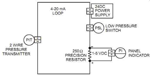
FIG. 20 Terminal block arrangement with a 250 ohms resistor.
The specification should define analog input signals as single-ended or differential inputs. Differential inputs are more expensive than single-ended inputs, but they will tolerate differences in ground potential and are therefore used for low-level signals.
Second, for discrete inputs, the specification should determine their distribution and types, the need for high-speed inputs (pulses) or bar code readers, and the quantity if inputs (typically, 20 to 30 percent spare capacity is required to handle future system modifications).
Third, for discrete outputs, the specification should determine their distribution and types, any requirements for surge suppression, the need for outputs to bar code printers, and quantity of outputs (here again, 20 to 30 percent spare capacity is required to handle future system modifications). Inductive equipment such as solenoid valves and relays generate a high-voltage transient when they change their mode from ON to OFF by switching hardwired contacts. This high insurgence of power drastically shortens the life of the switching contacts, damages the coil, and may generate interference with other nearby circuits. Voltage suppression diodes (also known as surge suppressors) are used in such a circuit to limit the effect of such transients. They are located in parallel with the wires to eliminate the surge. When the flow of current is interrupted, the diode conducts, providing a path for the current to decay to zero without generating a voltage surge. The correct suppressor must be properly selected since excessive suppression may cause a delayed release time. Surge suppressors are located typically at the inductive load.
If they are located at the switching device, they may be less effective because the wires between the switching device and the load may act as antennas, emanating EMI. Inductive loads switched by solid-state outputs alone do not require surge suppression.
Control Functions
In terms of control functions, the specification should define the approximate number of PID functions and determine the required math and logic capability or any other special functions such as ramping and tracking.
The specification should also state the required sampling and execution time and list the critical loops. It should also define the implementation philosophy for such loops, that is, hard wired or PESs with "hot backup" or "triple redundancy fault tolerant" (see Section 10 on alarm and trip systems). Finally, the specification should determine if controller redundancy is required.
Communication
For communication, the specification should determine if online communication maintenance is required and the acceptable update speed, define the link to other networks, and determine if communication redundancy is required.
Interface Functions
With respect to interface functions, the specification must determine the expected number of graphics and alarms (that is, identify priority levels, audible location, historical storage of info, etc.). It should also determine the trends and reports (that is, identify quantity, on-request or automatic printing, ability to include manual data in report, etc.). Refer to section "Operator Interface" later in this Section for more on this.
The specification should determine if the operator interface unit needs to perform complex calculations or statistical process control (SPC). It should define the acceptable system update time and state if similar functionality will be available on all CRTs (i.e., provide full redundancy). Finally, the specification should determine all hardware requirements such as the enclosure rating (see Section 12), mounting (desk or console-mounted), arrangement in control room, need for touch screen or membrane keyboards, requirements for a separate hardwired annunciator to handle critical alarms, monitor size, and the need for paper chart recorders (typically required for recording time increments of less than 1 sec).
Electrical Power
In terms of electrical power, the specification should identify an available quality and source and assess the effect of power failure on hardware, software, data retention, and data recovery.
Also it should assess the effect of suddenly re-established power (i.e., auto start, operator reset command, uncontrolled action, etc.). It should then decide if a UPS is required and, if so, which type of UPS (e.g., online UPS). Both direct current (DC) and alternating current (AC) are encountered in process measurement and control (see FIG. 21 and 22).
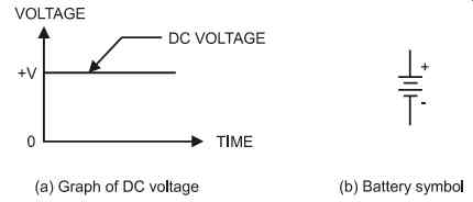
FIG. 21 Steady DC voltage.
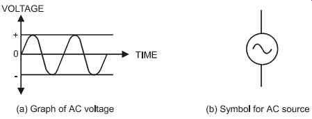
FIG. 22 Sine-wave AC voltage.
Manpower Requirements
For manpower, the specification should determine the requirements for engineering, operation, and maintenance, and identify a training program.
Startup/Shutdown Requirements
Regarding startup and shutdown, the specifications should define if these are manual activities or automatic functions performed by the control system, and therefore whether there is a need for feedback status for the sequenced startup and shutdown.
Shutdown Philosophy
The specification must define the shutdown philosophy and whether there is a need for separate push buttons, hardwired relays, or a separate PES for shutdown activities. It should assess the interaction with non-process alarms and systems (e.g., fire, gas emissions, lab results) and define the emergency shutdown requirements (manual and automatic) and their implications.
Motor Start/Stop
The specification should define a motor start/stop philosophy so as to maintain conformity among the various motors to minimize operator error. It should define the functionality of all controls (at the motor, at the motor control center [MCC], and in the control room) as well as their interaction and their priorities.
Operator Interface
The operators are the end users of a control system. Therefore, their needs should be met for all displays and controls. The implementation of an operator interface at a plant should be done in conjunction with the operators. If an operator is confused about the interface, the best PES in the world will not help. Under stress conditions, the operator must be capable of handling all the displayed information. It is important therefore that the operator be involved in developing the display and layout, including selecting colors. An operator interface provides a limited amount of available information at any one time, so the user must assess the distribution of information and its relevance as well as the number of monitors and their functionality. The typical monitor-based interface functions are graphics, alarms, trends, and reports. They are discussed in the following sections.
The performance of an operator interface can be gauged by its ability to quickly display large amounts of graphical and text information (i.e., call-up time and display refresh time) and at the same time providing this information clearly (i.e., screen resolution). When implementing an operator interface, the system designer should always assess the amount of data that an operator can monitor and the number of loops that he or she can control within a certain display.
The system designer needs to define, at the beginning of a project, the levels of data access and manipulation. Typically this information is available from the Control Scope Definition (see Section 14). There are generally four main levels of data access and manipulation.
1. Monitoring, where information can be viewed but not modified
2. Operating, where the operator can modify set points, operating modes, outputs to process, and start/stop sequences
3. Tuning, where the setting of PID loops can be modified
4. Programming, where software changes to the control system are made (applies to both off line and on-line programming)
The most common navigation tool is the keyboard. Some keyboards are sealed with a membrane and are commonly used on plant floors. In addition to keyboards, other system access devices commonly used to help the operator's eyes focus on the displayed data include touch screen and mouse (or similar device such as trackball). In comparison to a touch screen, a mouse (or trackball) requires smaller screen targets, does not experience parallax, and requires a more positive action. However, the ball picks up dirt more easily and requires more time from the operator to position the cursor correctly. Touch screens are easier to use and come more naturally to an operator. However, they require larger targets and fingers may smudge the screen and, after prolonged use, may damage some touch screen types.
When using a touch screen, the operator must know when the correct target has been reached-this is commonly done through reverse video. Another item to consider is target activation--i.e., should the target be activated when the operator's finger touches the screen or when the finger is removed. The second option allows the operator to correct his or her action.
When designing touch screens, the designer should locate common targets where the operator expects them to be on the screen (such as for Alarm Acknowledge and Alarm Reset). In addition, the designer should allow sufficient space around each target, label each target with its tag number and/or function, and provide visible and/or auditory feedback when a target is activated.
ISA has developed a standard to indicate the requirements for symbolically representing the functions of distributed control or shared display systems (ISA-5.3-1983, Graphic Symbols for Distributed Control/Shared Display Instrumentation, Logic and Computer Systems). It is applicable to all industries that use process control and computer systems.