AMAZON multi-meters discounts AMAZON oscilloscope discounts
The first electronic computer to use binary coding was EDV AC, built after the Second World War. It operated on binary numbers up to forty-three digits long, and was able to store, electronically, over 1000 such numbers.
It could add, multiply, subtract and divide at the then astounding rate of hundreds of calculations per second. It also used as much power as a small street of houses because it contained literally hundreds of valves. It went wrong once every few minutes of operating time, mainly because of the inherent unreliability of valves and because of the high voltages involved.
Needless to say, it was hugely expensive to build and run. It was however the grandfather of modern compact, efficient computers and used the same kind of organization, even down to magnetic tape as a bulk storage medium.
In order to reduce to a minimum the number of interconnecting wires required, all computers use a system in which buses carry information from one place to another inside, and sometimes outside, the computer. A bus is nothing more complicated than a group of wires, used together for the transmission of binary numbers. In Section 23 you saw the way in which binary numbers can be represented electronically--so a bus consisting of 8 wires (known as an 8-bit bus) will carry an 8-bit binary number--any number from 0 to 255. A 16-bit bus will carry a number between 0 and 65 535, and a 32-bit bus will carry any number from 0 to 4 294 967 295! Small personal computers tend to have an 8-bit bus for data, and a 16-bit bus for addresses. 'Data' and 'addresses' need explaining. Fig. 1 shows a system diagram for a typical computer.
The first main component in the system is the central processing unit (CPU). The CPU performs all the calculating, organizing and control functions, and is often called (inaccurately) the 'brain' of the computer. The CPU is connected to the rest of the system by three groups of wires: the data bus, the address bus and the control bus. Also connected to the buses are the memory and an input and output system.
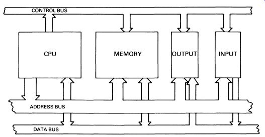
FIG. 1 system diagram for a microcomputer.
The data bus is used by the system to transmit binary numbers (data) from point to point. Data may be part of a calculation, or an instruction (more about that below). An 8-bit bus does not limit the computer to dealing with numbers less than 255, of course. Larger numbers are simply sent in two or more pieces, one after the other. Numbers up to 65 535 can thus be sent in two pieces, called the low-byte and the high-byte. A 'byte' is simply eight bits (it is a contraction of 'by eight') and is, in small computers, the amount of information that is dealt with at one time by the CPU. The address bus is used by the CPU (or other devices) to look at any individual byte of memory (either RAM or ROM); in small computers, a 16-bit address bus is used to provide a total memory capability of 65 535 bytes. This is referred to (confusingly) as '64 kilobytes', or '64K', the capital K being used to denote the 'computer kilo' of 1024.
The memory itself consists of a large number of bistable memory elements -- described in Section 23 -- along with appropriate decoding circuits.
The memory is used for storing data (information processed by the computer) and program (instructions telling the CPU what to do). Input may consist of a keyboard, or anything else that can feed information into the computer. Output may be a printer, visual display unit (VDU), or some other device enabling the computer's output to be passed on to the outside world.
1. CPU OPERATION
When the CPU is first switched on, it sends a signal down the address bus, corresponding to a 'one' in binary, 00000001. It also sends a signal down one of the two most important lines of the control bus, the READ line. At the same time, it prepares to receive a number down the data bus, and 'looks at' the data bus for information. The memory-decoding circuits connect the relevant memory bistables to the data bus, so that the contents of the bistables appear on the data bus. The CPU then loads the contents of the data bus into its own circuits, and the first byte of data is read into the CPU. It is crucial to an understanding of computers to know that what happens next depends entirely on the contents of the byte of data.
Although in a large computer the CPU may be made with large numbers of individual ICs, the CPU of a small computer will almost certainly be a single chip. This chip is called a microprocessor. Any computer which has a microprocessor as its CPU is called a microcomputer (regardless of its overall physical size). The microprocessor is a tremendously complicated piece of circuitry (see Figure 11.8) and can recognize the number that appears on the data bus. Since it is better to use a real-life example, we will use the Z80 CPU, manufactured by Zilog - it is probably the most popular of all microprocessors to date, having been widely used in many small computers including the best-selling Sinclair Spectrum. The Z80 can recognize almost 200 basic types of instruction. Assume that the byte just loaded from memory location 00000001 was 62. This is interpreted by the Z80 as an instruction. It tells the microprocessor that whatever is in the next memory location should be loaded into an 8-bit storage area (called a register) called register A. This done, the Z80 puts a new address on the address bus, 00000010 (2 in denary), looks at the data in that memory location, and loads it into register A. The Z80 now moves to memory location 00000011 (3 in denary: to prevent this guide becoming too long, we will use denary instead of binary from now on!). It expects another instruction: it might be to load register B with the next number, represented in Z80 code as 6. On to memory address 4 to find the number itself, then to location 5 for the next instruction. It might be 128, which means 'add the contents of register A to the contents of register B and store the result in register A'. Already, we have written a very simple computer program, to add two numbers: Load A with a number Load B with a number Add A to B and store the result in A.
This can be written more succinctly in a programming language called 'Z80 Assembly Language'. It looks like this:
l.D A,2 l..D B,3 ADD A,B
This, as you can see, adds 2 to 3, leaving the answer, five, in register A. In this example, the numbers to be added are immediately following the instructions, but they need not be. For example:
l..D A, (30000) LD B, (30001 > ADD A,B takes the numbers from memory locations 30000 and 30001, regardless of whereabouts in memory the program has been put. Remember that the CPU can treat the contents of any memory address as data or as program, according to the context.
Assembly Language is not itself recognized by the microprocessor, since Assembly Language uses letters and numbers; the microprocessor recognizes only binary data between 0 and 11111111. But it is convenient to write programs in Assembly Language as that is easier for humans to follow ... try to imagine a program consisting of, say, ten thousand binary numbers, then try to imagine finding a mistake in it! Assembly Language can be translated automatically into binary numbers (called the object code) by a suitable computer program, called an Assembler.
The CPU can do much more than merely add numbers. It is worth looking in a little more detail at the way a typical microprocessor is laid out, and how it works. The Z80 makes a good example.
The Z80 has 22 registers, including register A and register B that have already been mentioned. Remember that each register is actually a series of 8 bistables, and is capable of holding one byte. The purpose of many of the registers is too obscure to go into in a general book on electronics, but the more obvious ones are the main data registers of which there are seven of them, called A, B, C, D, E. H, and L. There is also a second set of registers, identical to the first, called the alternate register set. They are called A', B', C', D', E', H', and L'. There is also the PC, or program counter register- this is a 16-bit register. As we have seen, the registers are used for temporary storage of data. We can best see how they are used by means of an example program. For simplicity, we will ignore the input and output side of things, and assume that the computer starts off with a number in the A register, and that placing the answer in the A register at the end of the program is what is required. The following program is intended to carry out the following task:
1. check to see if the number is 10. If it is, simply put the 10 in the A register and stop.
2. If the number is 20, then the computer is to begin a program that starts at memory location 35000.
3. Any other number is to be doubled, and the answer put in the A register.
Here it is: CP 10 RET Z CP 20 ~JP Z, 35000 LD B,A ADD A,B RET
Operation of the program is simple enough. CP 10 ComPares the A register with the number, in this case 10. It does this by experimentally subtracting 10 from the A register. The next instruction is RETurn if Zero; so if the result of the experimental subtraction is zero, the RETurn instruction terminates this part of the program by returning to the point at which the program was started (or 'called'). This accomplishes the first part of the program specification.
The third and fourth lines of the program work in a similar manner, except that the JumP if Zero to 35000 instruction sets the PC register--the program counter--to 35000. This has the effect of interrupting the orderly sequence in which the Z80 looks at each memory location in turn, forcing it to carry on from location 35000. The last part of the job is accomplished in the next three lines. LoaD register B with the contents of register A is followed by ADD the contents of register B to register A. This is a way of doubling the size of the number in A. The final instruction is RETurn, which ends this part of the program.
This is a very simple example. Real programs would be much longer, and might use all the registers. You get some idea of the speed at which the Z80 works when you know that the program above takes a maximum of 20 microseconds to run.
The most important things to understand at this stage are:
1. the CPU is able to look at any of the memory locations, but in the absence of any instructions to the contrary will look in the memory locations sequentially immediately it is turned on;
2. the contents of each memory location (8 bits, or one byte) are read by the CPU, and what the CPU does next depends on the contents of the byte it has just read;
3. memory locations can be used for storing two sorts of information: the program that controls the activities of the CPU, and data. Data may be data that has been supplied to the computer from some external source, or it may have been put there by the CPU. There is no difference at all between the memory locations used for these two different purposes.
2. SYSTEM OPERATION
In looking at the computer, it is convenient to look at the individual components of the machine- the CPU, memory, keyboard, etc. But in order to make any sense of the computer, it is important to understand the way the whole thing operates as a system.
Fig. 1 is a very important diagram, as it shows the way the system works. The three buses are the channels through which the parts of the computer communicate with each other, and every computer is organized in much the same way. Almost all computers are designed in such a way that extra components can be added to the system, simply by plugging them into a multi-way socket that connects directly to the three buses.
The minimum components are the CPU and a memory. The lower addresses of the memory are generally ROM, so that immediately power is applied to the CPU it starts executing a program, bringing the system to life. The CPU can be directed by the program to look at an input device.
The most common input device is the keyboard. The keyboard may itself incorporate circuits that translate the key pushes into the relevant binary code. So pushing a letter 'e' would generate a binary number 10100110, to be applied to the data bus at the right instant and read into the CPU. Alternatively the CPU itself could run a short program, itself part of a larger program, designed to look at the connections to the keys, thus saving on hardware. Such a program is called a subroutine, and saves electronic components at the price of a small loss of operating speed.
Output devices also work by using the buses. The circuits driving a VDU can interrupt the CPU briefly to examine the relevant memory locations for the screen, then interpret them as characters or graphics shapes for display on the screen; the way in which the 'screen memory' is addressed is exactly the same method as the CPU uses, but the address and data buses are temporarily under the control of the VDU system.
At this point it is interesting to consider the way the memory locations are translated into a picture on the screen, and to examine what is known as the memory map of a typical computer. The memory map simply shows the allocation of the addresses that the CPU can access. This is the memory map of a typical low-cost microcomputer than can address 64K (65536 bytes).
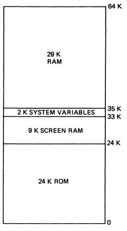
FIG. 2 memory map of a typical 64K microcomputer
The first ('lowest') 24K is occupied by the ROM. The ROM contains the operating system, the programs that do the housekeeping--all the operations of looking at the keyboard, loading and saving programs, con trolling input and output, etc. The ROM also contains a BASIC interpreter that enables the computer to run programs written in that language--more about that later. Remember that the microprocessor always starts at address 0 when switched on, so the ROM is always at the bottom of memory. The entire memory map above the ROM is filled with RAM 40K of it. Parts of the RAM are reserved for special purposes. The 9K between 24K and 33K is the screen RAM and is used to store the information which the computer translates into a picture on the screen of the monitor or TV. Fig. 3 shows the way the information is held.
The screen is divided into 24 lines of 48 characters, each character requiring eight bytes. The total RAM required for this screen is therefore 24 x 48 x 8 = 9216 bytes, or 9K. The bits in each group of bytes representing a character store the shape of the character itself, illustrated in Fig. 4.
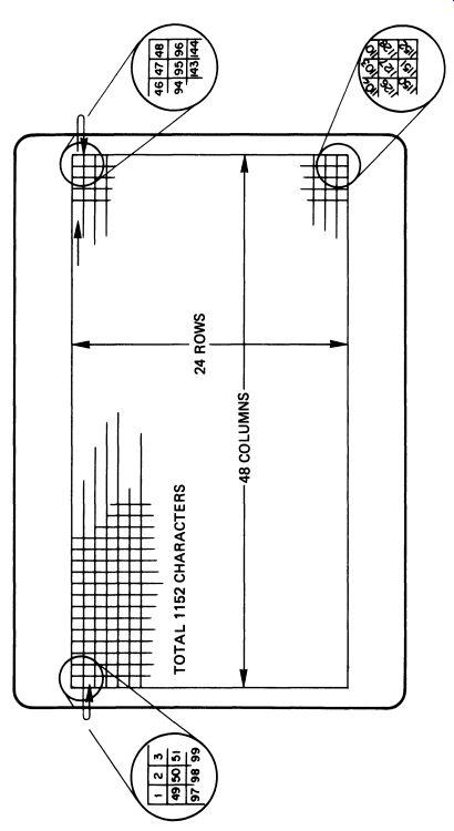
FIG. 3 the way information can be held in the computer's RAM, for
display on the screen; this part of memory is sometimes called the 'display
file'
As an illustration of how the computer works, consider what happens when you type a letter (make it an 'E') on the keyboard. To begin with, the microprocessor is running a program that is part of the ROM, checking the keyboard at regular intervals to see if a key has been pushed. At the same time the VDU system is reading the screen RAM and displaying it on the screen as a picture. You press the key. The microprocessor checks which key has been pushed and, according to which ROM program it is running, may store the result in RAM somewhere. The microprocessor next uses a look-up table, stored in the ROM, to find out which codes are required to produce the letter 'E'. It then checks other RAM locations to see whereabouts on the screen the letter should be printed, and finally writes the eight bytes that represent the letter into the relevant places in the screen RAM--note that the locations are not consecutive, but are actually 48 bytes apart. This will result in the letter 'E' appearing.
In practice the computer has to do a lot more than this, since the 'E' may or may not have significance in the context of the program that is being run.
Above the screen RAM (usually) there is another area of workspace that the microprocessor uses for storing temporary data like the printing position on the screen, the intermediate results of calculations, and all sorts of pieces of information that the system needs to remember. In this memory map, 2K of RAM is allocated. This leaves 29K of 'user RAM' available for programs. Which brings us to programming languages.
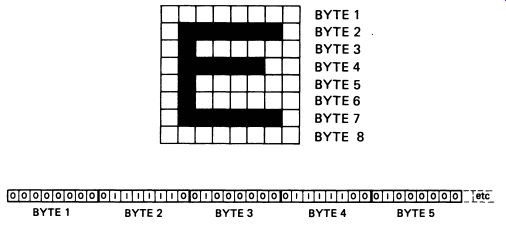
FIG. 4 the bits of eight bytes are used to represent a character
on the screen, like this 'E'
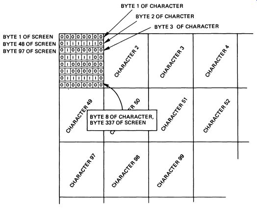
FIG. 5 the way characters are displayed on the screen of the monitor
3. COMPUTER LANGUAGES
The CPU of a computer--whether in a microcomputer or the largest main frame- is programmed in binary code. It is pretty well impossible for humans to use binary code for programming. The nearest usable language to the binary code the CPU needs is Assembly Language. Assembly Language instructions have a one-for-one correspondence to machine instructions: in other words, each Assembly Language instruction has an exact equivalent in binary code. Assembly Language is not easy to learn, and it takes a long time to program a computer to do anything useful. An Assembly Language program to input two six-digit decimal numbers and divide one into the other, expressing the result as a decimal number, would take an experienced Assembly Language programmer a full week to write. Clearly there needs to be an easier way.
Assembly Language is known as a low-level language because it is close to machine language. There are other computer languages that are much nearer to English, and are consequently easier to learn. Such languages can make it much simpler to program a computer, and are used wherever pos sible. Such computer languages are called high-level languages.
There are two classes of high-level language, compiled languages and interpreted languages. Both translate something closer to English into a code understood by the CPU, but they do it in different ways. We will start by looking at the most widely used computer language of all, BASIC. The name is an acronym for Beginners All-purpose Symbolic Instruction Code, and it was first used in the USA for teaching programming to university students, but has since been developed and extended until it can be used for a wide range of programming applications. BASIC is an interpreted language. A long and complex program (written in Assembly Language!) is kept in the ROM--this program is the BASIC Interpreter, and translates a program written in BASIC language into the binary code that the CPU requires. Here is a simple BASIC statement: 10 LET A=25.4/16.32 It is fairly obvious that this program line instructs the computer to let A (a variable, as in algebra) equal 25.4 divided by 16.32. It takes a few seconds to write such a line -but, via the interpreter, it makes use of machine code that may have taken months to write and refine. The line is typed into the computer, where it stored in RAM. The computer does not actually use the program line until instructed to do so. The instruction to start a BASIC program is RUN. When the computer receives this instruction it looks at the program line, and, a piece at a time, refers it to the interpreter. Each instruction is translated - as the program runs - into machine code that the CPU can understand. The interpreter does this by making use of an array of machine code programs in the ROM, calling each program into use as required.
The program line has a number (in this case, 10). Other program lines can be added, with higher or lower numbers, and the computer will sort them into order and run them sequentially. Here is a three line program: 10 INPUT a :20 LET b=a/4 30 PF:INT a, b When this program is RUN, the screen responds with some sort of 'prompt', perhaps a question mark. This means that the computer is waiting for an input. Type in a number, for example, 42. Almost immediately, the computer prints on the screen: 42 10.5 You should be able to see quite easily how the program works ... BASIC is as simple as that, at least for uncomplicated programs.
Here are two more BASIC programs, the second more complicated than the first. It is one of the most important features of BASIC that it is fairly obvious what they do, even if you are relatively new to programming:
10 PRINT "Type in the radius"
20 INPUT r
30 LET a=PI*r·····2
40 PRINT "The area of th€= circle is ";a
50 STOP
10 REM
Multiplication Tables
20 INPUT a
30 FOR i=l TO 12
40 PRINT a;" times ";i;" is ";ail<i
50 NEXT i
60 STOP
Another advantage of BASIC is its ability to detect problems in your pro grams. The interpreter, in translating the program, carries out many checks on whether or not the program makes sense. If it does not, the program stops running, and the interpreter generates an error message. Here is a BASIC program with a mistake in it:
10 INPUT a
20 LET b=a/0
30 PRINT b
When this program is RUN, the computer stops with the message:
DIVIDE BY ZERO ERROR AT LINE 20
The programmer has inadvertently asked the computer to divide a number by zero, which cannot be done, and the interpreter has detected it. Such an attempt, if made when using a program written in Assembly Language, would not be trapped, and the results would be unpredictable- more important, a machine-code routine with this sort of error might well over write itself, and would have to be reloaded.
The great snag with BASIC - and all other interpreted languages - is that by computer standards it is slow. The interpreter will spend most of its time translating the BASIC and choosing the relevant machine-code routines. It also spends a lot of time checking for errors. The result is that BASIC runs between 50 and 200 times slower than well-written Assembly Language, depending on what it is doing. For some purposes- such as stimulations, business and scientific applications requiring the manipulation of very large amounts of data, and arcade games, BASIC is not fast enough.
The next step upwards in speed is to use a compiled language.
BASIC is usually an interpreted language, that is, a language in which each instruction in the program is translated into machine code (by calling on a bank of stored machine-code routines) as the program is running.
Since the translation takes up most of the time, it follows that a big increase in the running speed of any given program could be obtained simply by carrying out all the translation first. This is the essence of a compiled language. The program is typed into the computer and stored.
When the program is finished, the computer is given an instruction to compile it. The compiler (equivalent to BASIC's interpreter) translates the program into machine code, which is also stored. The typed-in program is called the source code, and the compiled version is called the object code.
Notice that the program is 'translated' completely, before it is run. It is during this translation phase that any error messages are generated.
The source code is now no longer needed - it can be stored away on disk or tape (see below) for future reference. The object code can now be run by the computer, and since the translation has already been carried out, execution of the program is much faster.
There is no reason why BASIC cannot be compiled. Indeed, many BASIC compilers have been written and are commercially available. There are however a number of features of BASIC that make it a less than ideal language for treatment in this way; it was, after all, intended to be used as an interpreted language. Of all the compiled languages, Pascal is one of the most popular. The name is not an acronym this time, but is a tribute to Blaise Pascal, a seventeenth-century mathematician and philosopher. Pascal was designed at the outset to be a compiled language, and also to have a form such that its users are almost forced to write programs in an orderly, understandable way. Pascal compilers do not actually compile directly to machine code. Instead, they compile into an intermediate form called a P-code. The P-code is itself then run as an interpreted 'language', using a P-code interpreter! But the 'interpreter' is generally called a translator in this context, and the result is something that runs a lot faster than an interpreted language, because all the hard part of the translation (Pascal to P-code) is done before running the program.
The speed of a compiled language is a function of the quality of the compiler - all else being equal, the better the compiler, the faster the object code will run. The skill in writing a compiler is in getting it to produce a relatively economic code. Although it is beyond the scope of this guide to deal with programming languages in any detail, here is a short program segment designed to accept a 'y' or an 'n' (for yes and no) and nothing else as an imput, first in BASIC:
10 INPUT a$
20 IF a$=uy'' OR a$="n 11 THEN GO TO 50 30 PRINT "Tr·'f' again'" 40 GO TO 1 1)
50 PRINT no•·::••
... and in Pascal: F:EPEAT READ (answer); IF (answer()'y"l AND lanswer()'n'l THEN WRITE ('lry ayain!'l; UNTIL l answer•'y'l OR (answer •"n'l WRilE I'm~· I
There are, of course, many different high-level programming languages.
They are all easier to write than Assembly Language, and they all run slower, for no compiler or interpreter has yet been written that can equal well-written Assembly Language for efficiency. Programming computers is something people can still do better than computers! One of the oldest programming languages is FORTRAN (FORmula TRANslator). It is still an excellent language for science and mathematics, and bears a close similarity to BASIC, which was developed from it.
Another language that is still widely used is COBOL (COmmon Business Oriented Language) which is good for producing lots of long reports, inventory and stock control, buttoo 'wordy' for scientific work, graphic programs, or mathematics. Pascal itself is a good general-purpose language, but is not particularly good for control applications. For heavyweight applications - defense networks, for example - languages like FORTH and Ada are used. For experiments in artificial intelligence (trying to make a computer behave like a person) a language called LISP is often used. For applications programming where transportability Gargon for ease of translation for different makes of computer) is important, languages called BCPL and C are currently popular. All in all, there are enough computer languages to fill a tower of Babel - all with advantages and disadvantages that may recommend them in different applications.
To complicate matters even further, many software writers have found it efficient to use hybrid programs that are mostly written in a high-level language like BASIC but have machine-code subroutines (program sections within the main program) for the parts that need to work fast.
4. BACKING STORAGE
A computer can store information in RAM, and the operating system and interpreter can be written into ROM. There is, in addition to this, a need for some means of relatively permanent storage of data or programs--something that will store the information while the computer is switched off.
The simplest way to store such information is on magnetic tape, and even the cheapest home microcomputer has the means to record a program onto tape, and then to retrieve it. Cassette tapes are widely used because of their convenience. It works like this.
Assume, to start with, that you have typed a program into the computer, got it running satisfactorily, and now want to save it. To record the program on tape, you would simply type SAVE "my_program" on the key board, press the 'record' button on the tape recorder, and press ENTER (or RETURN) on the computer. The computer would then transmit the program in a suitable form for recording. When it has finished, you stop the tape - some machines have a built-in relay to do this automatically. A useful feature on some computers is a VERIFY command. You play the tape back into the computer after typing this, and it compares what is on the tape with what is in the relevant part of the RAM to make sure the recording is in order.
There are many different systems used for recording the information, but one of the best (and most commonly used) is pulse width modulation.
Very little in the way of hardware is required for this, so it is cheap, too.
When the operating system in the ROM receives the instruction to SAVE a program, it makes several checks. First, it checks to see that there is in fact a program in the computer. No point in saving something that isn't there! Second, it checks to see how long the program is. If the oper ating system is one in which the program may occupy different parts of the RAM, it also checks to see where the program starts. Finally (in most systems) it works out a checksum for the program--a meaningless number (like the number of binary 1s in the program) which is used to ensure that the program is intact when it is reloaded after saving. These various bits of information are put together into a header, a short block of data that is recorded before the program itself.
The header (program name/position in RAM/length/checksum) is recorded first, followed by the bytes that represent the program. The principles of pulse-width modulation were considered briefly in Section 22, but for computer programs it is necessary only to differentiate between 0 and 1. Fig. 6 shows the way the signal is encoded, a long pulse representing a 1 and a short pulse representing 0. The train of square-wave pulses is produced at a frequency within the audio range, so the resulting waveform can be treated just like sound and fed into the recorder's micro phone input. The maximum rate at which data can be recorded depends upon the frequency response of the recorder, and in practice about 1500 bits per second is a sensible maximum for reliability. Before any data is saved (even the header) the computer transmits a couple of seconds of a steady tone, to allow the recorder's automatic gain control circuits to settle at the right level. A medium-sized program of 20K would therefore take roughly 112 seconds to record. Manufacturers often use slower rates, out of pessimism about the quality of recorders that will be pressed into use with their computers.
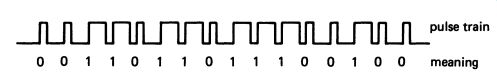
FIG. 6 binary data encoded for recording on tape.
Once the program is recorded on tape it can of course be stored indefinitely.
The program is recovered by typing LOAD "myprogram", and playing the tape into the relevant socket on the computer. The first part of the program to be received is the header. Once again, the computer makes a few checks. Do the program name typed in after LOAD and the one in the header correspond? If not, the program will not be loaded. Is there room in the computer for the program? Most computers are available with different amounts of RAM, and it is clearly pointless trying to load 40K of program into 32K of RAM. The computer sets the start address if necessary, and loads the checksum into a counter. Now the program is loaded, each 8 bits going into successive bytes of RAM. As the program is loaded, the checksum is decreased by 1 for each bit that is 1. When the program is completely loaded, the checksum ought to have reached zero. If it has not, or if it is less than zero, then something has gone wrong with the recording or playback, and the computer displays a TAPE WADING ERROR message on the screen.
While recording programs or data on tape is cheap and straightforward, it does have disadvantages. It is not particularly fast - a couple of minutes for a 20K program does not seem too bad, but ten minutes for 100K is long enough to be a nuisance. The limited speed of recording on cassette tape is mostly caused by the fact that small recorders are designed for audio frequencies. If a recorder is designed specially for digital use, the record and playback speed (computer people call it the read and write speed) can easily be pushed up to 50000 bits per second; at this rate, 100K of data can be transferred in about sixteen seconds.
The second disadvantages is that the recorder still requires some kind of manual intervention, and it would be much better if the computer could control the mechanical part of the recorder: this too is easily fixed by using a special design.
A number of low-cost microcomputers use just this technique ... a specially designed cassette tape recorder, either built into the computer itself, or sold as a specialized add-on.
Indeed, the mainframe computers of the 1960s generally used tape as a mass-storage medium for data. The tape drives were very specialized and very expensive. To increase the read/write speed they used wide tape (generally one inch) and at least nine record/play heads, allowing one byte and a check bit to be recorded simultaneously, increasing the speed by a factor of nine. Read/write speeds were also very fast, and computer tape still represents a very compact way of storing data.
Tapes however, do have a major drawback. Suppose the data the computer has to get at is in the middle of a reel somewhere! The tape has to be run forward to the relevant place (which has to be located somehow)
before the data can be loaded. If data or program segments are scattered at random along the tape, it is going to take the program a long time to run.
To some extent this difficulty can be reduced by careful organization of tapes, but what is really needed is a storage system that is more like RAM--a system in which the computer can find information almost immediately wherever it is recorded.
5. DISK STORAGE
Anyone who has used a tape recorder and a record player will have discovered that it is much easier to find a particular track on a record than it is on a tape. The record is effectively a random access storage system, whereas the tape is not. Computer tapes and disks are an exact parallel.
The cheapest kind of disk is the floppy disk. This is a thin circular sheet of flexible plastic, either 3.5 or 5.25 inches across. There is a hole in the center, and an outer protective sleeve of some sort. The surface of the disk is covered in magnetic oxide--the same material that is used for the coating on ordinary recording tape. Fig. 7 shows the layout of a typical floppy disk drive.
The read/write (record/play) head is brought into contact with the surface of the disk when the disk is inserted. The disk is spun round by a small motor, and the head is mounted on an arm that can move it to any point on the disk's radius. The arm is driven backwards and forwards by a stepping motor, a motor that is turned by signals generated by the computer. The computer can position the arm very accurately and can record either forty or eighty tracks across the disk.
Before the disk is used, it has to be formatted. This is an operation done by the computer, checking each of the tracks and dividing them up into sectors by recording marker pulses at various points. One track is reserved for the directory. When the computer receives an instruction to save something on the disk, it first checks the directory to see which parts of the disk are available for recording. The directory contains information about the name of what is stored, how much of it there is, and which parts of which tracks it is on. Having located a clear part of the disk, the computer makes an entry in the directory, then records the information itself.
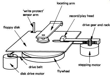
FIG. 7 a typical floppy disk drive mechanism, somewhat simplified
To load the data or program back from the disk, the computer simply looks in the directory to find out where the information is, drives the head to the relevant track, then loads the data from the relevant sectors. The whole operation can be very quick. In practice, the speed of floppy-disk storage varies enormously. A system with an old-fashioned or poorly written disk-operating system might take as long as a minute to find and load a short program, whereas a good system might do it in two seconds! A floppy disk typically holds between 80K and 800K bytes, according to design (and cost). Improvements are continually being made.
Although the disk drive will contain its own electronics, the computer system operating it must have suitable programs in its operating system.
Because of the amount of precision mechanical work - always expensive -
a floppy disk drive can cost as much as the microcomputer it serves. But for any serious use, a floppy disk is the minimum storage system required.
It is worth mentioning a system that provides disk-like facilities at a relatively low cost, the stringy-floppy. This oddly-named device uses cartridges containing a short (less than 10m) length of tape, arranged in an endless loop. Mechanically much simpler than the disk drive, the stringy floppy has the same kind of operating system as a disk, recording a directory on the tape in just the same way. The difference is that during a read or write cycle the tape whizzes round twice - once to find the directory and look at the entry, and again to fetch the data. If the loop takes 5 seconds to get round, then there is going to be an average 5 second over· head on each operation. Possibly as little as 2t seconds, possibly as much as 10 seconds. Nevertheless a well-designed stringy-floppy can easily work faster than a floppy disk with a poor operating system. Up to the time of writing, the only really successful stringy-floppy has been Sinclair Research's Microdrive, with an average loop time of about 6 seconds, and a capacity of about 100K bytes. The simplicity of the mechanical components (a greatly simplified cassette tape drive) makes the price less than half that of a comparable floppy-disk.
Really large computer installations, either business microcomputers, minicomputers or mainframes (in ascending order of size) may use hard disks. The smallest and cheapest is a design known as the Winchester disk.
The Winchester disk consists of several solid aluminum disks about half an inch thick and a few inches in diameter. Each disk is a precision component and is made perfectly flat on both sides. In principle it is similar to the floppy disk, but is sealed permanently in a perfectly dust-free chamber. The read/write heads skim across the surface of the disk without quite touching it, so there is no wear. The Winchester disk can typically hold several megabytes (millions of bytes) of data.
The biggest computers use bigger disks still, the 14-inch hard-disk pack. Several disks are fitted together into a 'pack', the whole pack being replaceable. Both sides of the disks are used, and each surface can hold about 30 Mbytes, although this is continually being improved. Hard disk systems are not cheap - currently a hard disk system costs about as much as a 'top of the range' family car.
6 MASTERING COMPUTERS
There is space enough in Mastering Electronics to give only the briefest outline of the way computers work. Readers wishing to find out more about computing and computer systems should refer to Mastering Computers by G. G. L. Wright (Macmillan), and also Mastering Computer Programming by P. E. Gosling (Macmillan).
QUESTIONS
1. Draw a system diagram linking the computer's CPU, RAM, ROM, input, and output.
2. Why is binary machine code never used to program a computer, no matter how simple?
3. Most small computers use BASIC for programming. State three important advantages that BASIC has over Assembly Language for programming.
4. Explain the following terms: (i) disk drive, (ii) compiled language, (iii) interpreted language, (iv) 64K RAM, (v) memory map.
5. Why must even the simplest computer be equipped with a ROM?