AMAZON multi-meters discounts AMAZON oscilloscope discounts
Introduction
There are many designs of crystal set -- they are all 'simple', and even the most seasoned radio amateur will build one of these every so often because it is something that never ceases to amaze! Although using modern components, the design is a period piece!
Design and construction
The circuit diagram of Figure 1 shows the simplicity of the circuit. The prototype was constructed on a wooden baseboard with an aluminum front panel, although this could be made of wood if you prefer.
Winding the coil always causes the most groans but when finished, gives the most satisfaction. The construction of the coil is detailed in Figure 2. A discarded toilet roll center is an ideal former on which to wind the coil. The coil will take up about 7 cm of the length of the tube, so assuming the tube is about 11 cm long, the ends of the coil will be about 2 cm in from each end of the tube.
The aerial coil, the primary winding of this radio-frequency (RF) trans former, is made from about 30 turns of 26 SWG enameled copper wire, wound on the matchstick ribs. These ribs should be about 2 cm long, and are glued on top of the end of the secondary coil after the secondary coil has been wound. The secondary winding has 140 turns with taps every 10 turns for 70 turns. This coil covers most of the length of the cardboard tube. To make your coil-winding easier, here are some tips for completing the coil and still having some hair left at the end!
_ Support the reel of wire on a dowel rod or pencil, clamped in a vice or held rigid in a vertical position by some other means. Don't leave it to trail around on the floor.
_ Have a small piece of sandpaper handy to remove the enamel from the copper wire, starting with the end coming from the reel. Remove about 1 cm only, until the shiny copper is visible all round the end of the wire.
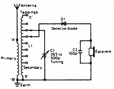
Figure 1--Circuit diagram of the crystal set
_ This part is the most difficult of all. Seasoned coil winders may have their own favorite ways of doing this, but for first-timers, play it safe and do it this way! Have a second bobbin (or a piece of stout card) ready, on which you will need to wind the wire loosely while you prepare the taps.
Then, starting from the free end of the wire, measure 125 cm and, at this point, remove about 2 cm of the enamel with the sandpaper. Bend the wire firmly back on itself in the middle of the bared area, and tin (cover with solder) the exposed copper. This is your first tap. Then repeat this six more times at 125 cm intervals, thus giving you seven taps; wrap the wire as you go, on to the second bobbin or piece of card. After the seven taps, you are half-way down your coil so, to begin winding it in earnest, wind the wire carefully from the second bobbin or card back on to the original reel of wire.
_ Looking at Figure 2, make two small holes about 3mm apart, about 2 cm down from the top of the tube, where wire C will be entering. Poke the end of the wire into one hole, then bring it out again through the other; leave about 10 cm of wire on the free end. Loop this wire in and out once more, thus anchoring the wire firmly.
_ Then, begin winding; keep the wire tight and make adjacent turns touch neatly. As you pass each tap, make sure it sticks outwards while avoiding flexing the wire too much; the wire is inherently weak at each tap.
_ When you reach the last 10 cm of wire, stop. Put two more holes, like the first, beside your stopping point, and anchor the end, D, of the coil in the same way as you did with end C. The secondary winding is complete.
Take a break after you have completed the next step!
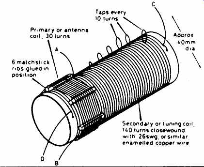
Figure 2 The coil is mounted on a cardboard tube as shown. Exact size is
not too important. Try different taps for best results
_ Prepare the six matchsticks for supporting the primary coil and glue these every 60 degrees around the end of the coil at D. Remove the enamel from the free end of the new copper wire on your reel and, using your favorite quick-drying cement, put a drop over the wire on one of the matchsticks, leaving 10 cm free as before. If you are using 26 SWG enameled copper wire, its diameter is 0.46mm, so 30 turns should occupy 14-15mm of the 20mm matchstick length. This will allow you to position the glued point such that the coil will be roughly in the center of the matchsticks. When the glue has set, wind the 30 turns and anchor this end of the coil in the same way. Then remove the enamel at the end of the 10 cm lead.
Assembly
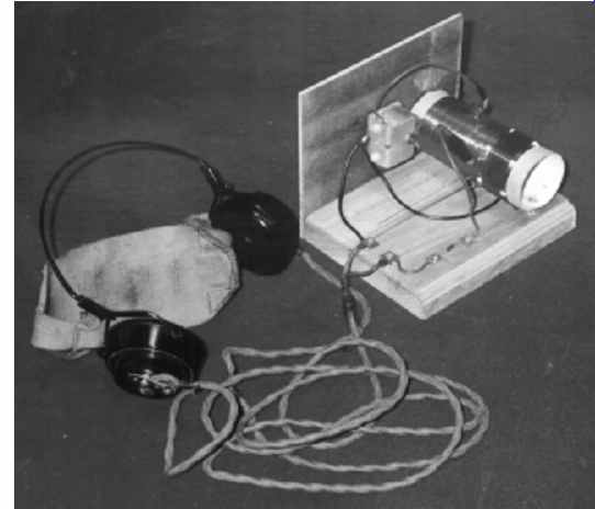
The coil former can be screwed to the baseboard at each end, before the front panel is screwed to the baseboard! As the photograph on the next page shows, the tuning capacitor is mounted in the center of the front panel. Five solder tags (or drawing pins as a last resort) should be screwed into the baseboard. The two to the left of the photograph are the connections to the earphones, the two along the rear edge have the diode, D1, soldered to them. One end of the diode (and, for once, you can connect the diode either way round!) is connected to one earphone tag. The other end has a flying lead of about 10 cm attached to it and terminated in a crocodile clip which is used to connect to one of the taps on the coil. The fifth tag secures the end, A, of the primary coil, to which you will attach the aerial. The earth tag on the tuning capacitor, C1, serves as an anchor point for the ground connections to B and D and to the other earphone tag.
Use
The longest piece of wire you have available to use as an aerial should be connected to the aerial tag just mentioned. If you can connect the earth tag of the tuning capacitor to a good electrical earth, this will help also. You should be able to hear something as you turn the tuning knob. Try adjusting the tapping connections on the coil -- change only one at a time, or you will never find the optimum positions. You now have a fully operational crystal set! Simple it may be, but this circuit illustrates some important principles which are used even in the most expensive receivers. Firstly, the coil, L1, and the capacitor, C1, form a tuned circuit which resonates at the frequency of the station you have tuned in. This selects the signal you want to hear. The modulation on this signal is removed by the detector , D1, and fed to the earphones, which act as transducers, turning the electrical energy into sound energy which you can hear. It doesn't need a battery or other power supply either!
Parts list
Capacitors:
C1 Variable capacitor of between 200 and 500 picofarads (pF) maximum
C2 100 picofarads (pF) min. ceramic
Additional items:
D1 Germanium, type OA47 or OA90
High impedance crystal earphone (not Walkman type)
Tuning knob
Wooden base, approx. 110mm square
Aluminum (or wood) front panel, approx. 80 × 100mm
Cardboard tube (toilet roll center), about 110mm long, 40mm diameter
Reel of 26 SWG enameled copper wire for both windings of L1