A simple 5.1-volt power supply can be constructed as shown in Fig. C-1. The 5.1 voltage level, which is close enough to the nominal 5.0 volts of TTL devices, will be maintained for load currents up to about 90 mA (enough to operate several flip flops) . At higher load currents, the output voltage will be determined by the voltage drop across resistor R, since the zener diode will stop conducting as the output voltage falls below 5.1 volts.
When the load current is 0, the current through the zener diode will be about 90 mA, causing a power dissipation in the diode of about 0.45 watts. Since the diode is rated for 1-watt dissipation, resistor R can be reduced to about 5 ohms. This will allow a larger load current to be drawn.
The drain on the battery can be reduced by increasing the resistance of R.
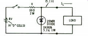
Fig. C-1. Schematic of 5-volt power supply for TTL circuits.
Prev: Link | --NUMBERING SYSTEMS
Next: GUIDELINES FOR SYSTEM DESIGN
Guide Index : Transistor-Transistor Logic (early 1970s)