AMAZON multi-meters discounts AMAZON oscilloscope discounts
This section is devoted to typical differential meter circuits. While the basic operating principles of all differential meters are the same, as discussed in Section 2, the circuits used in the various meters differ considerably.
MODEL 823A
The instrument selected for discussion is manufactured by the John Fluke Mfg. Co., Inc., Seattle, Washington, and is designated as their Model 823A. It is representative of the basic differential-meter principle in that it will measure both alternating current and direct current, as well as high resistances, on a differential basis. A photograph of the unit is shown in Fig. 5-1 and an overall block diagram is shown in Fig. 5-2.
Basic Theory of Operation
As shown in Fig. 5-2, the circuit consists basically of an a-c to d-c converter, a d-c vacuum-tube voltmeter (vtvm), and a 0- to 500-volt d-c reference. Overall operation of the 823A can be summarized as follows : To measure the approximate value of a d-c voltage, the unknown voltage is connected directly to the d-c vtvm. The a-c to d-c converter and 0- to 500-volt reference supply are then cut out of the circuit.
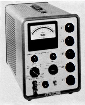
Fig_ 5-1 . John Fluke Model 823A differential meter.
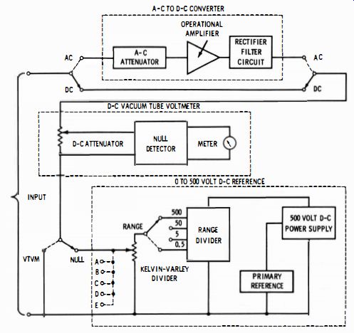
Fig. 5-2. Block diagram of the Model 823A differential meter.
To accurately measure a d-c voltage using the differential principle, the unknown voltage is connected across the series combination of the d-c vtvm, and the 0- to 500-volt reference supply. The reference voltage is then adjusted with the five voltage-readout dials until it matches the unknown voltage that is indicated by the null on the d-c vtvm. The unknown voltage is then read from the reference voltage dials.
All a-c measurements are made by first converting the a-c input voltage to a d-c voltage by means of the a-c to d-c converter. The 823A then operates essentially the same as for direct current. The following paragraphs provide a detailed analysis of the Model 823A circuits.
DC Vacuum-Tube Voltmeter Circuits
The d-c vtvm is composed of an attenuator, a null detector, and a meter. (See Figs. 5-3, 5-4, and 5-5 .) The heart of the d-c vtvm is the null detector in which the d-c signal input is modulated, amplified, rectified, and finally filtered to produce a d-c output. The chopper amplifier portion of the null detector has a high amount of negative current feedback. This makes the output current approximately equal to the signal voltage divided by the impedance of the feedback network, regardless of the amplifier characteristics. The high negative feedback also makes the amplifier relatively insensitive to the gain changes in individual stages due to aging and replacement. The output current from the null detector is indicated on a meter that has taut band suspension. This suspension does away with all friction associated with meter pivot stickiness.
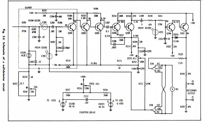
Fig. 5-3.
Null-Detector Circuit---At the input of the null detector (see Fig. 5-3), R20 1, C20 1, R202, and C202 form a double section, low-pass filter that reduces any a-c component present on the d-c voltage being measured. The difference between the voltage appearing at the output of the filter and the voltage developed across the feedback network is converted to an alternating voltage by V201 and V202, a series shunt photochopper. The photochoppers are driven by an astable multivibrator operating at 84 hz to prevent interference from line frequency pickup. The chopped voltage is amplified by solid-state amplifier Q201 through Q205 before being delivered to demodulator photocell V203. During half the chopper cycle the output of the amplifier is clamped close to the null-detector common potential by V203. During the other half-cycle the output is filtered by R22 1 and C2 11 to provide a d-c output.

Fig. 5-4. Schematic of an input attenuator circuit.
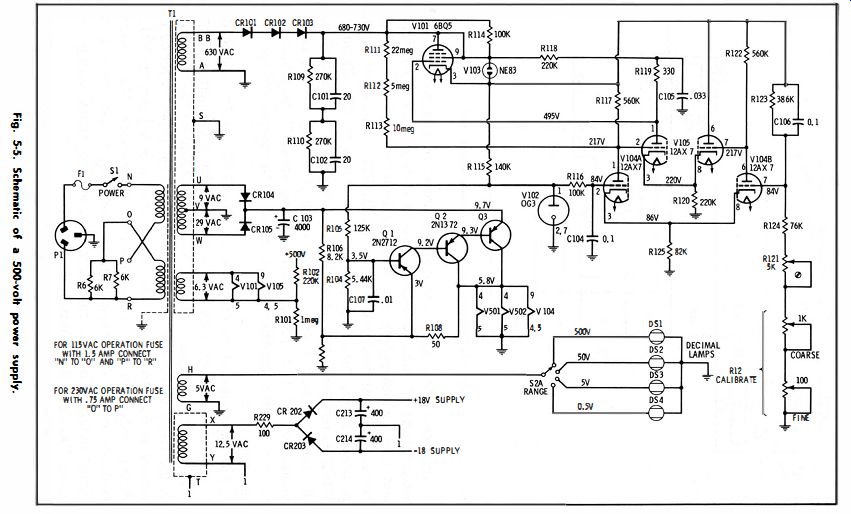
Fig. 5-5.
To prevent loading of the chopper amplifier, especially at high temperatures, the filtered output is fed to unity-gain amplifiers Q206 and Q207 which supply the necessary meter current. The voltage developed across feedback network R203, R204, and R20S is proportional to the meter (output) current. When DS202 illuminates V202, its resistance drops from about SO megohms to 5 kilohms, and the amplifier input is equal to the feedback voltage. When DS203 illuminates V201, its resistance drops from about 50 megohms to 5 kilohms and the amplifier input is equal to the output voltage from the input filter.
The impedance of the feedback network (R203, R204, and R20S) is adjustable between 9.28 and 10.5 ohms. Since the output current is approximately equal to the signal voltage divided by the impedance of the feedback network, a 1-mv signal voltage indicates an output current of 95.1 to 108 u-a. The output current is adjusted to 100 u-a during calibration by means of the feedback network. Thus, current feedback makes the output current essentially proportional to the signal voltage. For full-scale deflection, a 1-mv signal voltage will cause 100 u-a to flow through the meter.
A recorder output is picked off divider string R224, R1, and R22S. Output level control R1 provides a means of adjusting the output voltage up to a maximum of at least 18 millivolts at full-scale deflection. The voltage at the output terminals is proportional to the meter reading.
Variable resistor R212 provides a means of adjusting the output current of the amplifier to zero when there is no input signal by utilizing the negative bias voltage on the emitter of Q201 and the positive bias voltage on the emitter of Q205 . The gain of the amplifier is adjusted by means of R205 in the feedback circuit.
Input Attenuator Circuit---In the d-c vtvm mode, four positions on the vtvm attenuator (Fig. 5-4.) selected by range-switch section S2C provide the necessary reduction of the 500-, 50-, 5-, and 0.5-volt ranges for proper null-detector input. For this mode the resistance of the attenuator, and thus the input resistance of the 823A, is 50 megohms (R2 through R6). In the d-c differential mode, the voltage difference (unknown voltage minus reference voltage) is reduced by four positions on the vtvm attenuator selected by null switch sections S3C and S3D to give full-scale deflections corresponding to inputs of 10, 1, 0. 1, and 0.01 volts . For full-scale deflection corresponding to 0.00 1 volt the voltage across the attenuator is fed directly to the null detector. Although the resistance of the vtvm attenuator is 10 megohms (R6 through R11) for the 10-, 1-, 0. 1-, and 0.01-volt null ranges, and 1 megohm (R7 thru R11 ) for the 0.001 -volt null range, this is not the actual resistance of the 823A.
NOTE: The input resistance of most differential voltmeters is determined by dividing the unknown terminal voltage by the current drawn from the unknown. The current drawn from the unknown is equal to the difference between the unknown terminal voltage and the internally known voltage divided by the resistance of the input attenuator. Since the reference voltage is equal to the unknown voltage and the source voltage at null, no current is drawn from the unknown; the input resistance is therefore infinite.
In the a-c vtvm mode, null switches S3C and S3D, and a-c/d-c switch sections SSH provide connection to only one position on the vtvm, regardless of where the range switch is set. This is because the output of the a-c to d-c converter is 5 volts d-c for full input on each range. In the a-c differential mode, the voltage difference (converter output voltage minus reference voltage) is reduced by the same positions on the vtvm attenuator as for d-c differential measurements.
Because of this and the fact that the converter puts out 5 volts d-c for full input on each range, the null range used must be multiplied by the a-c null multiplier indicated by the range switch to find the full-scale difference between the unknown voltage and the reference voltage.
The input impedance for the a-c vtvm and a-c differential mode depends upon the input impedance of the a-c to d-c converter and its attenuator. The input impedance is thus dependent on the setting of the range switch and is 1 megohm, 35 pf for the 500-volt a-c range; 1.1 megohm, 35 pf for the 50-volt a-c range; and 1 megohm, 50 pf for the 5- and 0.5-volt a-c ranges.
0-to-500-Volt Reference Circuit
When the 823A is used for differential voltage measurements, an internal voltage is nulled or matched against an unknown voltage.
An extremely accurate reference voltage is therefore required. This is obtained from the 0- to 500-volt reference. (See Figs. 5-5 and 5-6.) The 0- to 500-volt reference is composed of a well-regulated 500-volt supply, a range divider, and a Kelvin-Varley five-decade attenuator.
The output of the 500-volt power supply is applied directly to the Kelvin-Varley attenuator for the 500-volt d-c range. In the 50-, 5-, and 0.5-volt d-c ranges the range divider reduces the voltage to 50, 5, and 0.5 volts before it is applied to the Kelvin-Varley attenuator.
For any a-c range, the range divider always reduces the voltage to 5 volts. The Kelvin-Varley attenuator divides its input voltage (500, 50, 5, or 0.5 volts) into 50,000 equal increments, any number of which may be selected by setting the five decades with the voltage readout dials. The output of the Kelvin-Varley attenuator, therefore, provides an extremely accurate reference voltage.
500-Volt Power Supply--The 500-volt power supply (Fig. 5-5)
uses three diodes (CR101, CR102, and CR103) and a filter network (R109, R110, C101, and C102) to supply unregulated d-c voltage to VIOL The voltage is regulated by comparing a sample of the output voltage tapped off a divider string (R123, R124, R121, and R12) with the voltage from reference tube V102 in differential amplifier V104. The control action of the differential amplifiers continuously adjusts the voltage drop across V101 in order to keep the sample voltage equal to the voltage of the reference tube. Any difference in voltage or error is amplified by VI04 and VI05, and thus changes the voltage drop across V101 to maintain the output at a constant 500 volts.
For proper operation, a highly stable and accurate balance of amplification must be maintained between the two halves of differential amplifier V104. The filament supply for VI04 must be regulated to maintain this balance. Regulation is provided by a transistor regulator which supplies constant voltage to the filaments of V104.
(The filaments of the a-c to d-c converter tubes V50I and V502 are also supplied by this regulator.) A filtered, full-wave rectifier (CR104, CR105, and C103), which is regulated by a three-transistor network (Q1, Q2, and Q3), supplies the regulated d-c filament voltage. One side of the filaments is connected to the reference-supply common (0 volts), while the other side is maintained at approximately 5.9 volts through the emitter-collector junction of Q3. The output of Q1 drives a Darlington connection of Q2 and Q3. Any variation in the unregulated supply causes a corresponding change in the voltage across the emitter-collector junction of 3 so that the filament voltage of V104, V501, and V502 remains stable.
Range Divider---In the 500-volt d-c range (Fig. 5-6), the output of the 500-volt supply is passed directly to the Kelvin-Varley attenuator by range switch section S2F. In the 50-, 5-, and 0.5-volt d-c positions, range resistors (R320 through R330) selected by section S2E, divide the reference voltage to 50, 5, and 0.5 volts before it is switched to the Kelvin-Varley attenuator by section S2F. With the a-c/d-c switch set to a-c, section SSG provides connection to the range resistors that divide the reference to 5 volts. This signal of 5 volts is then passed to the Kelvin-Varley attenuator by section S5F. The voltage applied to the Kelvin-Varley attenuator is always 5 volts for alternating current because the a-c to d-c converter always supplies up to a maximum of 5 volts to the vtvm attenuator.
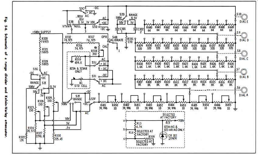
Fig. 5-6
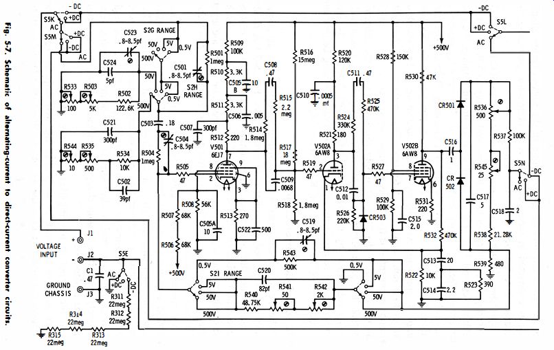
Fig. 5-7
Kelvin-Varley Attenuator-In Fig. 5-6 the five Kelvin-Varley decade resistor strings R40 1 through R455 and associated voltage dials A through E (S6 through S I 0) provide a means of making the four precision voltages (500, 50, 5, and 0.5) adjustable. Note that each string, with the exception of the first, parallels two resistors of the preceding string. Between the two wipers of S6 (voltage dial A), then, there is a total resistance of 40K (80K paralleled by 80K). With the range switch in the 500-volt position, a total voltage of 100 volts d-c will appear across these two wipers.
There will be 10, 1, and 0.1 volts d-c across the wipers of S7, S8, and S9, respectively. Voltage dial E (S10) picks increments of 0.01 volt d-c from the last decade. These voltages are reduced by a factor of 10 for each lower voltage range. The Kelvin-Varley resistors are matched for both temperature coefficient and tolerance, thus providing an overall attenuator accuracy of 0.002 percent absolute. With the null switch in any null range the output of the Kelvin-Varley attenuator is connected in series with the vtvm attenuator, providing the accurate 0- to 500-volt reference required.
Reference Supply Adjustments--Variable resistor R121 (Fig. 5-5) is used during calibration to set the 500-volt supply to 500 volts with calibrate control R12 (Fig. 5-5) set at its center of rotation. This allows the reference supply to be adjusted to 500 volts by means of the calibrate control at any time deemed necessary. With the operate calibrate switch held at calibrate, a fixed percentage of the 500-volt supply is compared with the precise potential of an internal standard cell or to a zener diode (Fig. 5-6) depending on the model. Any difference in potential is fed to the null detector to give an indication on the meter so that the 500-volt supply can be set with the calibrate control. The fixed percentage of the reference supply is set accurately during calibration by means of R3 18 (Fig. 5-6). The 50-, 5-, and 0.5-volt range resistor networks are set accurately during calibration by means of R323, R326, and R329 (Fig. 5-6).
A-C to DC Converter Circuit
The a-c to d-c converter is composed of an attenuator, an operational amplifier, and a rectifier-filter circuit. (See Fig. 5-7.) A diode in the rectifier filter circuit is used to convert the unknown alternating current into pulsating direct-current, which is then filtered to obtain a d-c voltage that is proportional to the average value of the a-c input voltage. The output, however, is calibrated to indicate the rms value of a pure sine wave.
An operational amplifier containing three resistance-capacitance coupled amplifier stages with high negative feedback is used to make the rectification characteristics of the diodes linear and stable. The amplifier achieves a midband loop gain of approximately 70 db with virtually a flat frequency response from 20 hz to 10 khz. The high negative feedback makes the amplifier practically noise-free and relatively insensitive to gain changes in individual tubes due to aging and tube replacement.
At the output to the amplifier, full-wave rectification is used to return negative feedback to the grid of the first amplifier tube. The attenuator is used to reduce the a-c input voltage by a factor of 10 to 100, as required to restrict the operational amplifier input to 5 volts maximum for full-scale inputs of 50 to 500 volts, respectively.
Circuit Operation--All a-c measurements are made by first converting the a-c input voltage to a d-c voltage. The converter provides a d-c output of 5 volts when full-range voltage is applied in each a-c range. In the 5-volt a-c position, range switch sections S2G and S2H connect the input binding posts directly to the converter input. In this case the converter feedback is of such value that the d-c output voltage is equal to the rms value of the converter input a-c voltage.
In the 500- and 50-volt a-c positions, an input attenuator reduces the unknown alternating current by a factor of 100 and 10, respectively.
The operation of the converter is then the same as for the 5-volt position. In the 0.5-volt a-c position, range switch section S2I and section S2J provide connection to feedback resistors that allow the converter to produce an output that is equal to ten times the a-c input.
Thus, an output of 5 volts d-c is provided for all full-scale inputs.
Null Indications With A-C-Measurements---When making a-c differential measurements, the null range used (times the applicable a-c null multiplier) must be used to represent full scale on the 832A meter. This is due to the way that the converter is designed. For the 500-volt a-c range the converter produces a d-c output voltage equal to 1/100 of the a-c input voltage. Thus, the a-c null multiplier for the 500-volt range position is X100. For example, when the range switch is set to 500 and the null switch is set to 0.01, full-scale meter deflection represents a one-volt (100 x 0.01 ) difference between the unknown voltage and the amount set on the voltage-readout dials. By similar reasoning, the multipliers for the 50-, 5-, and 0.5-volt a-c ranges are X10, X1, and X01, respectively.
Converter Circuit Adjustments---For 0.5-volt converter gain, R536 and R545 at the output of the converter are adjusted. The gain of the amplifier for the 5-volt range is adjusted by means of R542 and R54 1 in the feedback network. The high-frequency response of the amplifier input is adjusted by means of C504, while C5 19 adjusts the high-frequency response of the 0.5-volt feedback circuit. The attenuation of the 500-volt attenuator is adjusted with R535 and R544, and the attenuator high-frequency response is adjusted with C50 1. The attenuation of the 50-volt attenuator is adjusted by R503 and R5 33; the attenuator high-frequency response is adjusted by C523.
A-C/ DC Polarity Switch Circuit
The a-c/ d-c polarity switch is provided for selecting either the a-c or d-c mode of operation. The connections provided by this switch can best be understood by reference to the diagram of Fig. 5-8.
When the a-c / d-c polarity switch is set to a-c, the a-c to d-c converter is switched into the circuit by sections S5K, S5L, S5M, and S5N. Also sections S5F and S5G are used to switch 5 volts d-c to the Kelvin-Varley divider. When in the a-c vtvm mode, S5H is used to provide proper attenuation of the d-c attenuator.
The a-c/d-c polarity switch may be set to either of two positions, positive or negative, for the d-c mode of operation. As shown in Fig. Fig. 5·8. Function diagram of a polarity switch.
5-8, the a-c/ d-c polarity switch does not reverse the input posts when going from the positive to negative d-c position. Instead, it reverses the meter and the internal reference supply. If the instrument did not contain positive and negative d-c positions, the grounded side of any unknown voltage that is negative with respect to ground would have to be connected to the upper-input binding post. This would ground the upper post and effectively place C1 across the input terminals. Even if C1 were disconnected, there would still be considerable capacitance across the input due to transformer winding capacitance and stray wiring capacitance. With this capacitance across the circuit being measured, several problems would arise. The polarity switch provides equal convenience in measuring positive or negative voltages without the occurrence of these problems.
Differential Voltmeter Applications
A differential voltmeter is well adapted for the measurement of resistance. There are two basic procedures, one of which is well suited for measurement of resistances above 1 megohm, while the other is better suited for precision measurement of lower resistance values. The following sections describe how a differential voltmeter can be used to make such resistance measurements.
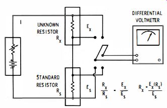
Fig. 5-9. Method for measuring standard resistors.
Measurement of Standard Resistors
It is possible to make accurate resistance measurements of lower value (1 megohm or less) resistors by comparing the voltage ratio between a standard resistor and the unknown resistor to be measured.
If a standard resistor Rs is connected in series with the unknown resistor (Rx) as shown in Fig. 5-9, and the current through both resistors is the same, the ratio of the voltage drops, as determined by the differential voltmeter, is the same as the ratio of their resistances. To obtain accurate and valid results it is essential that the current (I) remains constant throughout the measurement. This is easily verified by repeated measurements of the voltage drop with Rs and Rx alternately connected in the circuit.
The accuracy of resistance measurements using this method depends on the accuracy of the voltmeter and standard resistor.
The accuracy and resolution of the voltmeter used will be a prime factor in determining the measurement accuracy. If the ratio of the resistors is such that the voltage drop across Rx and R. is measured on the same voltage range, then the basic error of the voltmeter will cancel out. If, for example, the voltmeter had a specified accuracy of better than ±0. 1 percent, and the voltmeter was in error by +0.005 percent, then the value of the unknown resistor (Rx) would be indicating that the error of the voltmeter cancels out. The error contributed by the voltmeter will consist only of the error caused by the linearity characteristics of the Kelvin-Varley divider. If the ratio of resistors Rx to Rs is large enough that the voltage measurement requires a voltmeter range change, then it is necessary to consider the basic error contributed by the voltmeter. This illustrates the need for knowing the capabilities and limitations of the voltmeter and compensating for these limitations by knowing the errors associated with your voltmeter. The resolution of the voltmeter must also be known.
NOTE : Resolution is defined as the smallest quantity discernable using a given measurement-device. The resolution of any measurement should always be greater than the accuracy expected.
Standard resistors can be obtained which typically provide calibration accuracies of ±0.005 percent, or better, and will remain within 50 parts per million of their certified value over a temperature range of 20° to 30° centigrade. The power coefficient of the resistors used is an important factor when attempting accurate measurements.
Tables 5-1 and 5-2 indicate the current and power permissible for standard resistors as determined by the degree of accuracy required.
It is suggested that the values of current and power indicated in Tables 5-1 and 5-2 be considered as guidelines in order to minimize the possibility of errors caused by self-heating in the resistors being measured.
The following example is intended to give an idea of the results obtainable by measuring resistors with a precision differential volt meter.
Measurement of a 10-ohm standard resistor Rs = value of the standard resistor = 10.000 ohms.
Es = voltage drop across the standard = 1.0000 volt.
Ex = voltage drop across the unknown = 1.0035 volt.
Rx = ?: (Rs) = ?:g (10.000) = 10.0035 ohms.
Accuracy of standard resistor = ±0.005 % .
Accuracy of the voltmeter Kelvin-Varley divider = ±0.002 % . Total inaccuracy of the measurement ±0.007%. The total error of the measurement is shown as the sum of the standard resistor and voltmeter errors.
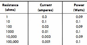
Table 5-1. Maximum Current and Power for Certificate Limit of Error
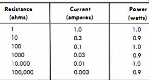
Table 5-2. Maximum Current and Power for ±0.02-Percent Limit of Error
One of the major advantages of this type of measurement is that the circuit under test need not be disturbed. Therefore, there is no loading effect, and the lead and contact resistances have no effect.
This type of measurement is well suited for the measurement of four terminal resistors that are part of complicated networks. However, the measurement circuit should be grounded at only one point to prevent the possibility of ground loops.
Measurement of High Resistance
Differential voltmeters provide a feature that allows them to be used for the direct measurement of high resistances. The use of a differential voltmeter for this purpose provides a convenient and rapid method for 'measuring resistances from 1 megohm to 250,000 megohms. The applications for this type of measurement include the measurement of leakage resistance of capacitors, transformers, and insulators.
Fig. 5-10 shows the basic circuit configuration for accomplishing the measurement. This circuit consists of a known power supply voltage that can be selected by the voltage range switch and applied to a precision Kelvin-Varley divider. The setting of the Kelvin-Varley divider determines the exact voltage that is applied across the null detector connected in series with the unknown resistance, Rx. The input impedance of the null detector (which is usually on the order of 1 or 10 megohms, depending on the null range setting and the model of the instrument) is used as the standard resistor (Rx) in the circuit.
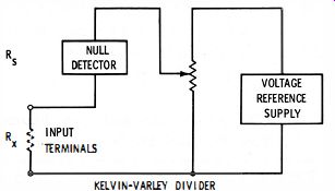
Fig. 5-10. Method for measuring high resistances.
The measurement of resistance with a differential voltmeter is a direct application of Ohm's law: the measurement of the current through the unknown resistance and the voltage drop across it. With an unknown resistor connected to the input terminals of a differential voltmeter, the current through the unknown resistance is equal to the voltage indicated by the null detector divided by the null-detector input resistance. Likewise, the voltage drop across the unknown resistance is equal to the voltage measured on the Kelvin-Varley divider minus the voltage indicated by the null detector.
Since R=E/I, the voltage drop across the unknown resistance divided by the current through the unknown resistance is equal to the unknown resistance value.
For practical measurements, it is recommended that resistances up to 50,000 megohms be made with the null-detector meter needle at end (full) scale. With the most common differential voltmeter, the current will be known to within approximately 4 percent (3 percent from the null detector and 1 percent from the null-detector input resistance).
However, the accuracy of the measurement depends not only on the accuracy of the current through the circuit, but also on the percentage of the applied voltage that is dropped across the unknown resistance, compared with the voltage dropped across the null detector. For example, if the Kelvin-Varley dials indicated 1.1 volts, and the null detector indicates an end-scale reading of 1.0 volt (assuming a 10-megohm input resistance), then using the following equation we can determine the value of the unknown resistance, Rx : where,
Rx = unknown resistance in megohms,
E = voltage indicated on the Kelvin-Varley divider,
Em = voltage indicated on the null detector,
Rn = resistance in megohms of the null detector.
If we compute the value of Rx, we find it to be 1 megohm:
10 Rx = T (1.1 - 1) = 10 x 0.1 = 1 megohm
But, if we re-compute it, assuming that the null detector voltage reading is in error by +3 percent, we find that the value of Rx to be low by 32 percent. Although the accuracy of the null detector is +3 percent, this 3 percent error in 1 volt represents 32 percent error in the 0. 1 volt dropped across the unknown resistance. Conversely, we see that as the ratio of voltage drop across the unknown resistance becomes large with respect to the voltage drop across the null detector this error will be practically eliminated.