AMAZON multi-meters discounts AMAZON oscilloscope discounts
Introduction
Although the photoelectric and rectifying properties of selenium were discovered before 1900, the first commercial rectifier using this material was promoted in Germany around 1928. Its subsequent development and application in Europe proceeded along similar channels with those of the copper oxide rectifier in the United States. As the manufacturing techniques were improved and new ideas incorporated, the resulting selenium rectifier displayed important and inherently superior characteristics over the copper-oxide rectifier for certain applications.
The selenium rectifier was introduced in the United States in 1938 by the Federal Telephone and Radio Corporation, a subsidiary of the International Telephone and Telegraph Company. As introduced, these selenium rectifier cells were limited to a maximum AC input voltage of about 14 volts, root mean-square. Improvements in the barrier layer during the early 1940's permitted an increase in the applied AC voltage to 18 volts, rms per cell. Subsequent work during World War II resulted in present (1956) cell rating of 26 volts rms.
The higher voltage rating per cell made practical what is known in the trade as miniature selenium rectifier assemblies--in contrast to the regular power selenium rectifier assemblies. These miniature selenium rectifiers provide an easy and economical solution to DC power problems in radio and television receivers. The demand for these miniature selenium rectifiers made it necessary to achieve true mass production and stocking of a range of rectifiers easily available from jobbers and distributors anywhere. This, compared to the custom production and poor availability of other type of rectifiers previous to this time, made the selenium rectifier quite popular.
The selenium rectifier's electrical characteristics, long life, light weight, availability, and potential for improvement have given it a meteoric rise since its introduction and at the present time it occupies the number one position in popularity and demand.
Production
Selenium rectifier cells use a circular or rectangular base plate of steel or aluminum. The aluminum base plate is generally preferred because of lightness, better heat dissipation, and the elimination of the rust problem. The surface of the base plate is roughened by sandblasting or chemical etching so as to provide a good bond between it and the semi conductor which is to be applied. Then the roughened base plate is nickel plated to reduce the electrical contact resistance between it and the semiconductor. The next step is the application of the semiconductor; purified selenium powder with a trace of bromide, chlorine, or iodine is dusted upon the roughened surface of the base plate and this combination is heated and simultaneously subjected to a pressure of about 1000 pounds per square inch. The resulting selenium layer, of an amorphous nature, is reduced to a crystalline form by further heat treatment to improve its electrical conductivity.
The adherence of the selenium semiconductor layer on the roughened base plate is a function of the thickness of the layer as well as its coefficient of expansion relative to that of the base plate. Better adherence is achieved with a thinner layer of selenium semiconductor--the limit to the thinness of the selenium layer being porosity or pin holes in the selenium and low reverse resistance of the rectifier cell. In practice, the usual thickness of the selenium layer ranges between 0.003 to 0.005 inch.
The base plate is now placed into a mask and the selenium surface is sprayed with a low melting-point alloy (selenium melts at about 217 degrees Centigrade). The whole surface of the selenium layer is covered with the exception of a narrow ring at the center and at the periphery of the base plate. The purpose of these rings is to provide insulation between the alloy front electrode and the metal base plate electrode. The sprayed alloy surface constitutes the front or counter-electrode of the selenium rectifier cell and is its cathode (rectification polarity). The alloy usually comprises from 15 to 20 percent cadmium, the rest being bismuth and tin; the plastic temperature of the alloy is around 95 degrees Centigrade and its melting temperature varies from 110 to 170 degrees Centigrade depending upon the percentage of its contents.
NICKEL-PLATED ALUMINUM OR STEEL BASE PLATE (BACK PLATE)
SELENIUM LAYER (SEMICONDUCTOR 0.003" TO 0.005'' THICK) BARRIER LAYER (ELECTRO-FORMED)
ALLOY FRONT OR COUNTER-ELECTRODE ( LOW TEMPERATURE ALLOY) CROSS-SECTIONAL VIEW FRONT VIEW
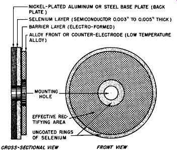
Fig. 5-1. Front and Cross-Sectional View of the Selenium Rectifier Cell.
In Fig. 5-1 is shown a sketch of a selenium rectifier cell in plan and cross-sectional view. The central hole is used for mounting purposes when the cell is assembled into rectifier stacks. The uncoated selenium peripheral and inner rings which insulate the front electrode from the base plate are shown in the front view sketch. The layer of selenium and the front electrode are very thin in practice; these layers are represented to an exaggerated scale in the cross-sectional view. The barrier layer between the selenium and the alloy front electrode is only a few molecules thick. The effective rectifying area of the selenium cell is equal to the area of the front electrode.
The electrical connection to the selenium rectifier cell of Fig. 5-1 is made to the back surface of the base plate and to the front surface of the front electrode. When a DC potential is applied to the cell so that the base plate is polarized positive and the front electrode is polarized negative, a much larger current will flow through the cell than when the polarity of the cell is reversed. The current flow through the cell is in a direction normal to the plane of the cell disc. The magnitude of the current flow depends directly upon the effective rectifying area of the cell and upon the applied voltage, although the relationship between the voltage and current is not linear.
Thus each selenium rectifier cell as pictured in Fig. 5-1 forms a complete, half-wave, rectifying element with the back plate acting as a support and one electrode, and the alloy surface acting as the other electrode, the combination presenting a one-piece rectifier requiring no high pressure contact for rectification.
In assembly of these rectifier cells into a stack, contact with the base plate is made by a metal washer or terminal member while contact to the front electrode or alloy layer is made by means of a spring contact plate. The amount of pres sure exerted by this contact plate is determined by the thickness of an insulating washer placed between the cell and the contact plate.
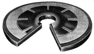
Fig. 5-2. Cut-Away View of a Selenium Rectifier Cell. (Courtesy of General
Electric Co.)
Fig. 5-2 is a photograph of a General Electric selenium rectifier cell using the construction described. The cut-away permits a view of the cross-sectional nature of the cell. The first layer at the left of the photograph is the aluminum back plate. The next layer is the selenium semiconductor. The succeeding, spotted white layer is the alloy front or counter electrode. Between the selenium and the alloy layer is positioned the blocking or barrier layer which is formed by heat treatment and electroforming. The petal-like spring contact engaging the front electrode is the last element of the selenium rectifier cell shown.
Another type of selenium rectifier cell construction se cures the same advantage of assembly and front electrode contacting without the petal-like spring contact.
The reverse resistance of the previously described selenium rectifier cell falls off too rapidly to permit the cell to be put into practical service; to make a practical cell, it must be further processed--electroformed and heat treated.
The barrier layer between the front electrode and the selenium semiconductor is electroformed by applying a rectified AC or a pulsating DC voltage in the reverse direction while the rectifier cell is heated in an oven which is regulated closely in temperature. Further heat treatment and seasoning at critical temperatures completes and stabilizes the barrier layer. At the beginning of the electroforming the applied voltage is low so as to prevent overheating the cell; as the reverse resistance builds up, the applied voltage is increased until its maximum value is a few volts over the rated voltage of the cell. The theory is that the electroforming increases the thickness of the barrier layer to a small extent and performs an electrical cleaning of the selenium surface adjacent to the front electrode by removing the surplus electrons. The process has little effect on the forward characteristic of the cell except to slightly increase the forward resistance.
The selenium rectifier cell thus processed is ready for assembly into rectifier stacks. The cell is generally made in disc form in diameters ranging from 7/8 inch to 4 3/8 inches, square plates ranging from 1/2 inch to 5 inches or in rectangular plates up to 6 1/4 x 7 1/4 inches. Special rectifier discs for high voltage or high frequency applications as small as 1/4 inch in diameter are commercially available.
Construction
For practical application of the rectifier cells discussed previously, it is necessary to assemble them in the required number and sequence into rectifier stacks in the manner de scribed in Section 3. For such rectifier stacks to be stable, it is necessary that its constituent cells be firmly assembled together, that is, mechanical pressure be permanently applied to hold the cells in place. H, however, this mechanical pres· sure is applied to the active surface of the selenium cells, either the cell reverse resistance may be greatly reduced (poor efficiency due to increased leakage current) or a short circuit in the cell may result. Hence, two different schemes are commercially used to avoid these risks. This results in two physically different types of selenium rectifier cells currently used for assembly into the rectifier stacks. Consequently, stacks using one or the other type of selenium rectifier cell will be slightly different in physical structure. The principal difference between the two types of rectifier cells is in the method of contacting the front electrode or alloy surface. In the first type of rectifier cell, no front electrode is applied near the mounting hole (inner ring of Fig. 5-1) and the stack assembly pressure is applied to this area by a bakelite washer. A spring washer makes electrical contact with the front electrode surface at a pre-determined and limited pres sure. This spring washer may be in the form of a petal or solid spring washer. The photograph of the General Electric selenium rectifier cell, shown in Fig. 5-2, clearly illustrates an example of the petal spring washer contact to the front electrode.
When this first type of rectifier cell is assembled into a rectifier stack, the required number are placed in the proper sequence upon a threaded and insulated stud. A metal terminal or washer makes electrical contact with the rear of the base plate of each cell and connection to the front electrode is made by the described spring washer. The predetermined pressure exerted by this spring washer is controlled by the thickness of an insulating, bakelite washer placed between the alloy surface of the cell and the adjacent inner surface of the spring washer. The advantage of this construction is that the electrical characteristics of the stack are not disturbed by the degree to which the terminal assembly nuts of the threaded stud are tightened. The reason for this is clear, when it is recalled that no front electrode is applied to the center ring of the rectifier cell and consequently no pressure sensitive barrier layer is present here to be affected. This permits mechanical pres sure to be applied to the spacing and pressure limiting washers for stack assembly purposes without affecting the reverse resistance of the rectifier.
The second type of selenium rectifier cell does not re quire the contacting spring to the front electrode. Electrical connection to the front electrode is achieved by means of a metal washer or terminal strap in the rectifier stack assembly. To avoid electrical shorting to the base plate and reduction of the cell reverse resistance because of rectifier stack assembly pressure, the inner, uncoated ring of selenium is coated with an insulating varnish, then the selenium surface is sprayed with the low temperature alloy. This alloy surface does not extend to the edge of the plate or circular disc but is usually applied with a slight margin to eliminate the possibility of direct shorts to the base plate. This accounts for the outer or peripheral ring of uncoated selenium shown in the plan view of the cell in Fig. 5-1 and in the cut-away photograph of Fig. 5-2. The selenium layer is now insulated from the front electrode over the area where pressure will be applied when the rectifier stack is assembled and electrical connection to the front or counter electrode can be made by means of a metal washer or terminal strap as required in the stack assembly.
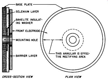
Fig. 5-3. Cross-Sectional and Plan View of Selenium Rectifier Cell Using
Insulating Washer Principle.
1. END INSULATOR
5. PETAL CONTACT SPRING
9. MOUNTING STUD WITH NUTS
2. INSULATING WASHER
6. SELENIUM RECTIFIER CELL
10. INSULATING TUBE
3. STEEL WASHER
7. BAKELITE SPACER
11. STEEL END WASHER
4. TERMINAL LUG
8. CONDUCTING SPACER
12. LOCK WASHER
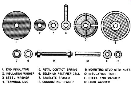
Fig. 5-4. The Elements of a Selenium Rectifier Stack Using the Contact Type
Cell.
Another scheme to obtain the same result for the second type of selenium rectifier cell is shown in Fig. 5-3. To one face of the aluminum or steel base plate there is applied an insulating washer, concentric with the mounting hole. Then the selenium layer is applied and processed. Over the selenium layer is applied the low-temperature alloy to constitute the front electrode. The front electrode, as described before, has an inner and outer margin to prevent shorting of the front surface with the metal base plate. The effective rectifying area is the area which the front electrode and the base plate have in common, that is, less the area of the insulating washer.
The advantage of the insulating washer type of selenium rectifier cell is that somewhat better cooling of the cell is achieved when it is assembled into a stack, for the cell face is not covered by a spring contact member. Moreover, the insulating washer type of selenium rectifier cell can be freely dipped into insulating varnish without the risk of the varnish penetrating between the front electrode and contact plate.
Having selected the selenium rectifier cell type and pre pared the cells, it is necessary to grade them (described in Section 3) before assembly into rectifier stacks. Fig. 5-4 shows the elements of the contacting spring washer type of selenium cell stack assembly. The assembly of these elements into a full-wave bridge with one cell per arm is illustrated in Fig. 5-5.
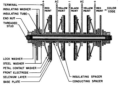
Fig. 5-5. Selenium Rectifier Stack Construction.
Full-Wave Bridge, Using Contact Type Cell.
In Fig. 5-6 are shown the elements of the selenium rectifier stack using the insulated washer type of cell. Fig. 5-7 shows in cross-section the selenium rectifier stack using the components of Fig. 5-6 in a full-wave bridge, utilizing one cell per arm of the bridge.
1. STACK NUT
4. INSULATING WASHER
7. SELENIUM RECTIFIER CELL
2. LOCK WASHER
5. TERMINAL LUG
8. INSULATING TUBE
3. STACK ENO WASHER
6. CONDUCTING ANO SPACER WASHER
9. THREADED STUD
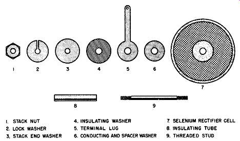
Fig. 5-6. The Elements
of a Selenium Rectifier Stack Using the Insulating Washer Type Call.
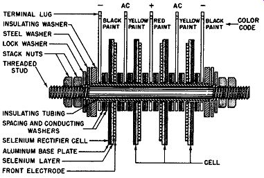
Fig. 5-7. Selenium Rectifier Stack Construction. Full-Wave Bridge, On a
Cell per Arm. Cells are of the Insulating Washer Type.
Please note again that the cross sectional studies of the selenium rectifier cells in both Figs. 5-5 and 5-7 are grossly exaggerated as to the thickness of the layers constituting the cell. This is done so that the individual layers can be easily identified; normally, the whole cell may be less than 0.05 inch thick.
After the assembly of the rectifier stack, the whole stack is given one or more coats of insulating varnish and, if required, a fungus treatment.
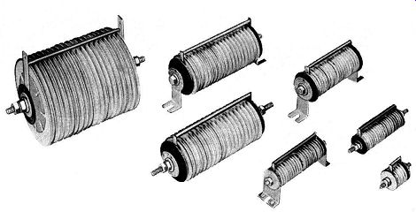
Fig. 5-8. Selenium Rectifier Stacks Manufactured by General Electric Company.
(Courtesy of General Electric Co.)
The terminals of a selenium rectifier stack are color coded in the following manner: the yellow coded terminals are the AC input terminals, the red coded terminal is the positive terminal, and the black coded terminal is the negative terminal of the DC output. Should the rectifier stack constitute a half wave rectifier, then one terminal is imprinted + or painted red.
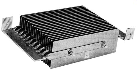
Fig. 5-9. Heavy Duty Selenium Rectifier Stack Using Rectangular Cell Plates.
(Courtesy of Vickers, Inc.)
Examples of commercial selenium rectifier stacks are shown in the photograph of Fig. 5-8. Fig. 5-9 is a photograph of a rectangular selenium rectifier cell stack manufactured by Vickers, Inc. of St. Louis. This heavy duty selenium rectifier stack is 4 1/8 inches high, 18 inches wide, and 12 inches long. Six of these stacks carefully finished to withstand high humidity and corrosive atmospheres are used to deliver 18 kilowatts DC at 12 volts, 1500 amperes, in electroplating service. Fig. 5-10 is a photograph of a three-phase bridge selenium rectifier stack.
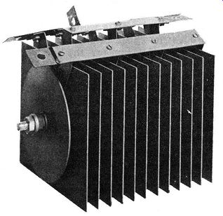
Fig. 5-10. A Three-Phase Bridge Selenium Rectifier.
Fan Cooling, 24 Volts AC Input, 60 Amperes DC Output. (Courtesy of Seletron
Division of Radio Receptor Co., Inc.).
Elements of the Selenium Rectifier Cell
Previously, in Section 2, it was stated that all known metallic rectifiers can be represented by a generalized rectifier cell and shown to comprise four elements; these cell elements are:
1. Base or support plate.
2. Semiconductor.
3. Barrier layer.
4. Front or counter electrode.
This description of the generalized rectifier cell applies to the selenium rectifier cell studied in this section. It has an aluminum or steel disc or plate which is the support plate; this base plate does not enter into the rectification process but serves as a stable platform for the semiconductor and is one electrical terminal of the rectifier cell. The selenium layer is the semiconductor; it is especially processed to possess good electrical and mechanical bond to the support plate.
The barrier or insulating layer is electroformed between the selenium layer and the front electrode by electrical and heat treatment. The front electrode adjacent to the barrier layer is a metallic alloy more abundant in free electrons than is available in the selenium semiconductor. This combination behaves as a half-wave rectifier cell, for, when the applied polarizing potential is directed from the selenium to the adjacent metal front electrode across the barrier layer, the current flow is much more abundant than for the reverse potential. That is, current flows more freely through the selenium cell when the base plate is polarized positive and the front electrode is polarized negative.
This condition of the base plate acting as the anode while the front electrode acts as the cathode of the selenium cell for current flow, is opposite to the condition described for the copper-oxide rectifier cell in Section 4. For example, Fig. 4-7 shows that the forward direction here is obtained when the copper base plate is positive and the lead front electrode is negative. It appears then that the copper-oxide and the selenium rectifier cells rectify in an opposite sense. But note that the reason for this difference is in the position of the barrier layer. In the copper-oxide rectifier cell the barrier layer is adjacent to the support plate, whereas in the selenium rectifier cell the barrier layer is adjacent to the front electrode.
If the general rule is used to determine the forward direction, no confusion results because of physical differences in the construction of the various metallic rectifier cells.
This general rule states that the forward direction is that resulting from the potential difference being directed from the semiconductor to the adjacent metal electrode across the barrier layer; that is, polarizing the semiconductor positive and the adjacent metal electrode across the barrier layer negative.
Following this rule the polarity for the forward direction is readily determined and the rectification in "opposite sense" for selenium and copper-oxide rectifier cells is no longer confusing.
(A) Exaggerated Cross-Sectional View of Selenium Rectifier Cell.
(B) Schematic Diagram Showing Rectification Polarity.
(C) Exaggerated Cross-Sectional View of Half-Wave Selenium Rectifier.
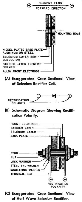
Fig. 5-11, Elements of Selenium Rectifier Cell.
In Fig. 5-11A the generalized metallic rectifier as exemplified by the selenium type is specified. The forward direction as defined in the foregoing is also shown. In Fig. 5-11 B the electrical symbol for this rectifier cell is shown. The arrow points toward the forward direction; however, when the cell is used as a half-wave rectifier the rectification polarities are as shown here. (Refer to Section 3.) In Fig. 5-llC a sketch is given to show how the selenium cell may be assembled into a practical half-wave rectifier.
Volt-Ampere Characteristics
The principal function of a rectifier cell is to freely pass current in one direction (forward) while blocking or greatly limiting its passage in the opposite direction (reverse). If the rectifier cell freely passes current in the forward direction, this implies that the resistance to current flow in this direction is low; hence, the resulting forward voltage drop across the cell must also be low. If the current in the reverse direction is blocked or held to a minimum value, the reverse resistance must be large; hence, the voltage drop across the cell for the reverse direction of current flow must be large.
The maximum value of reverse voltage drop is limited by the breakdown potential of the barrier layer of the cell.
Pursuing these thoughts further may lead to saying that a quality of merit for a rectifier cell may be considered to be a low voltage drop across the cell in the forward direction, and, in the reverse direction, a minimum leakage current.
From this thought it can be understood that the volt-ampere curves of a metallic rectifier cell are essential, if an intelligent appraisal of the cell is to be made, for the volt-ampere curves present in graphical form the above described information. These curves are obtained by applying a DC voltage to the rectifier cell and observing, without delay, the corresponding current flow. The tabulated results from these observations are then plotted to produce the volt-ampere curves.
The volt-ampere curves for a selenium rectifier cell are shown in Fig. 5-12. The characteristics of the cell shown here are identified as static characteristics since all the values are measured by DC meters. See Section 2 for the technique employed in these measurements. Moreover, the curves are designated as typical characteristics for a selenium rectifier cell because such characteristics for the cell are not fixed but are dependent upon temperature, life of cell, and past history. Furthermore,-even cells of the same age and history (same production run) may have considerable variation from the typical volt-ampere characteristic curves shown.
For the curves (forward and reverse) shown in Fig. 5-12 the horizontal axis is graduated in positive and negative volts corresponding to the forward and reverse potentials. The vertical axis or the ordinate is graduated in hundreds of milli amperes per square inch above the horizontal axis to correspond with the forward current; below the horizontal axis the ordinate is graduated in milliamperes per square inch to correspond to the leakage current. These current values are approximate and are based on a rectifier cell having an effective area of one square inch and operating at a temperature of 25 degrees Centigrade (about 77 degrees Fahrenheit).
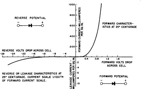
Fig. 5-12. Volt-Ampere Characteristic of a Selenium Rectifier Cell at 25
degrees Centigrade.
Plotting the ordinate of these curves in milliamperes per square inch makes the characteristics representative for all sizes of selenium rectifier cells. The lower current scale has been multiplied by a factor of 100 times the upper current scale, since the reverse current is usually so much smaller than the forward current that this scale enlargement is necessary to enable comparison of the forward and reverse proper ties of the cell.
The normal current loading in the forward direction for the naturally-cooled selenium rectifier cell is about 250 milli amperes per square inch, corresponding to a forward potential drop across the cell of about 0.6 volt DC at an operating temperature of 25 degrees Centigrade. Much higher current loadings can be obtained by the employment of fins, artificial cooling, or a combination.
In the reverse direction the maximum working voltage commercially employed at present (1956) is 26 volts rms.
One manufacturer, however, advertises cell ratings of 33 volts rms. At an applied voltage of 26 volts rms, the leakage current is approximately 3 milliamperes per square inch at an operating temperature of 25 degrees Centigrade.
The volt-ampere curve for the reverse direction is the characteristic which requires prompt observation during the experimental run. The reason for this is that this characteristic is materially affected by the degree of formation that exists in the cell before the experimental run; it is also affected by any additional forming that may occur while the curve is being obtained.
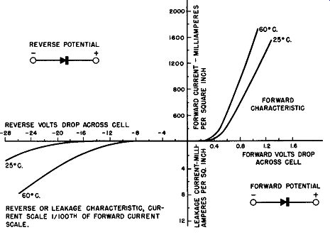
Fig. 5-13. Effect of Temperature on the Volt-Ampere Characteristic of a
Selenium Rectifier Cell.
Temperature Characteristics
The selenium rectifier cell has a negative temperature coefficient in the forward direction; that is, as the cell temperature is increased the forward resistance decreases. Hence, for the same voltage drop across the rectifier cell the forward current increases as the cell temperature increases. The relationship between cell current versus cell voltage in the for-ward direction, for two cell temperatures as parameters, is presented in Fig. 5-13. These are static characteristics for a selenium rectifier cell having unit area of one square inch.
Note, for example, that at 1.0 volt drop across the cell the forward current at 25 degrees Centigrade is about 1000 milli amperes per square inch, while at a cell temperature of 60 degrees Centigrade the forward current for the same voltage drop is 1400 milliamperes per square inch. This clearly illustrates the negative temperature coefficient of the selenium rectifier cell in the forward direction.
Fig. 5-14. Temperature Characteristics of the Selenium Rectifier Cell.
Another way to present the effect of temperature on the selenium rectifier cell is illustrated by Fig. 5-14. This graph represents the voltage drop across the rectifier cell versus cell temperatures for two values of constant current in the forward direction. Again, it can be seen from this that the forward resistance of the selenium cell decreases as the cell temperature increases.
The net result of temperature on the selenium rectifier cell in the reverse direction is also given in Fig. 5-13. For example, the leakage current at minus 20 volts is greater at 60 degrees Centigrade than at 25 degrees Centigrade. How ever, the effect on the reverse resistance due to the temperature is not quite as simple as that described for the forward resistance. Whether the temperature coefficient is negative, positive, or constant is dependent upon the applied reverse voltage and cell temperature. Refer to Fig. 5-15; note that, for an applied reverse voltage of 18 volts to the selenium rectifier cell, the leakage current is almost constant over the temperature range of minus 50 to plus 75 degrees Centigrade.
This is a desirable property as the heating due to the leakage current is less at the higher operating temperature.
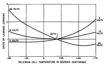
Fig. 5-15. Leakage Current versus Cell Temperature for Rated and Reduced
Applied Voltages.
For an applied reverse voltage of 2 volts to the selenium rectifier cell the temperature coefficient becomes positive in the temperature range of 0 to plus 75 degrees Centigrade.
This 2 volt operating voltage is, of course, not practical but the curve is presented to illustrate the complicated nature of the reverse resistance characteristic with temperature.
For a reverse voltage of 26 volts applied to the selenium rectifier cell, its rated voltage, the temperature coefficient is essentially negative over the whole temperature range showing an increase of leakage current for a decrease in temperature and a decrease in current for an increase in cell temperature.
In practical rectifier circuits these resistance changes in either the forward or reverse direction are of little importance as the resistance of the rectifier is only a small part of the total circuit resistance (about 1/10th), so the effect of the temperature change on the rectified output is quite small.
Voltage-Resistance Characteristics
A satisfactory metallic rectifier cell must present a very low resistance to the passage of electrical current in the forward direction and a very high resistance to current flow in the reverse direction. The perfect metallic rectifier has zero resistance in the forward direction and infinite resistance in the reverse direction. This perfection has not been achieved in metallic rectifier cells; all commercial metallic rectifiers have some resistance in the forward direction and the resistance in the reverse direction is not infinite. The greater the ratio of the reverse to the forward resistance, the better the electrical performance of the rectifier cell.
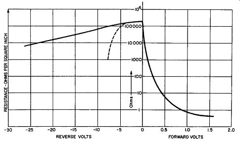
Fig. 5-16. Static Resistance Curve for Selenium Rectifier Cell.
In the selenium rectifier cell the forward and reverse resistance is not fixed or linear but varies with the magnitude of the applied potential. Refer to Fig. 5-16; this is the graphical presentation of the resistance of a unit area of a selenium rectifier cell versus the various applied potentials in the forward and reverse directions. The horizontal axis of this graph is graduated in positive and negative voltage increments re presenting the forward and reverse applied potentials respectively. The vertical axis or the ordinate of the graph is graduated in ohms in logarithmic increments because the resistance range is too great to otherwise properly display the resistance change.
The information displayed in Fig. 5-16 is obtained at an operating temperature of 25 degrees Centigrade for a selenium rectifier cell having an effective area of one square inch.
It can be observed from this voltage-resistance graph that the cell has a finite resistance value of about 150,000 ohms. As the applied voltage is increased in the forward direction, the cell resistance decreases rapidly at first up to an applied voltage of one volt, after which the resistance tends maintain a constant, low value.
As the applied voltage is increased in the reverse direction, the cell resistance also decreases but much more slowly--if the applied voltage is kept within the cell's rating.
Within the cell's voltage limits the reverse resistance curve is approximately logarithmic.
The graph of Fig. 5-16 applies to a selenium rectifier cell of unit area in which the reverse resistance has been previously formed electrically in the manner discussed previously. If the selenium rectifier cell has not been electrically formed, its reverse resistance will not be large nor will its barrier layer withstand as large an applied reverse voltage.
Such an unformed rectifier cell has a reverse resistance which substantially follows the graph of Fig. 5-16 until the reverse resistance reaches 3 or 4 volts; beyond that voltage the reverse resistance falls off very sharply, as shown by the dotted curve in the reverse resistance section of the graph.
(A) Half-Wave Rectifier
(B) Voltage Waveform Across Resistive Load.
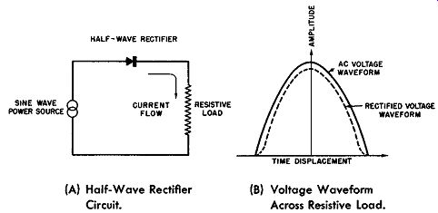
Fig. 5-17. Waveform Distortion Due to Resistance Change of Selenium Rectifier
Cell.
Oddities in the operation of a metallic rectifier, such as the selenium rectifier cell, are caused by the fact that the resistance of the cell is not constant but decreases as the current through the cell increases. A good example of an operational oddity is illustrated by the Fig. 5-17. In Fig. 5-17A an AC power source, having a sinusoidal voltage waveform is applied to the series combination of a selenium rectifier cell (half wave rectifier) and a pure resistive load (no inductive component). The voltage developed across the resistive load is not a rectified sine wave because the voltage drop across the rectifier cell will be relatively greater when the current flow through the cell is small than when it is at its rated maximum.
This is shown in Fig. 5-17B. Here the solid curve represents the applied voltage of sinusoidal waveform; the dotted curve represents the rectified voltage drop developed across the load as a result of current flow through the rectifier cell. The effect of the non-linear resistance of the rectifier cell is to change the form factor of the voltage waveform across the load from its theoretical value of 1.11 to about 1.15. Form factor is defined as the ratio between the rms and the average value of a waveform. The form factor of a sine wave is 1.11.
Voltage Rating of the Cell
Voltage rating of a rectifier cell is defined as the root mean-square value of the AC voltage applied to the cell. Selenium rectifier cells are presently operated at 26 volts rms, although one manufacturer advertises cell ratings of 33 volts rms.
If the selenium rectifier voltage rating is taken as a criterion, the rate of developmental improvement of this type metallic rectifier is quite phenomenal. After World War II, these rectifiers were being marketed at 18 volts rms per cell. In less than five years the rated voltage was pushed up to 26 volts rms, and the end is not yet in sight.
The voltage rating is based on an ambient temperature of 35 degrees Centigrade. Voltage ratings are derated above ambient temperatures of 50 degrees Centigrade (122 degrees Fahrenheit). Current Rating of the Cell The current rating of a metallic rectifier cell is the maximum current that may be passed through it in the forward or low resistance direction within the cell's thermal rating.
This current is expressed as the average DC amperes as read on a D' Arsonval type ammeter. For the selenium rectifier cell the current rating is about 250 milliamperes per square inch at 35 degrees Centigrade for a self-cooled stack (no fins or artificial cooling). Above an ambient of 35 degrees Centigrade the current rating must be derated.
Current rating is, of course, dependent upon stack design and upon the cooling methods employed. With forced cooling in a 35 degree Centigrade ambient temperature, it is regular practice to operate selenium rectifiers up to 250% of normal rating or about 650 milliamperes per square inch.
Voltage Regulation
Since the selenium rectifier cell is essentially a resistive device, it has a property described as voltage regulation.
Voltage regulation is defined as the ratio of the difference between the output voltage at no load and full load to the full load output voltage--expressed in percent. (Refer to Section 4.) The difference between the no load and full load voltage is the potential drop across the selenium rectifier in the forward direction occasioned by the cell's forward resistance. Thus, the voltage regulation of the selenium rectifier cell is a function of its forward resistance. If was found previously in this section that the selenium rectifier possesses a non-linear forward resistance, that is, the cell's forward resistance decreases as the forward current through it increases. This property partially counter-balances the increase in voltage drop across the rectifier cell as the load through the cell increases, resulting in a forward voltage drop which remains practically constant and low over a wide range of load current.
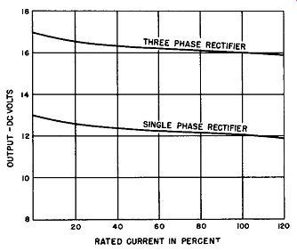
Fig. 5-18. Voltage Regulation Curves for Selenium Rectifier Cell for Single-and
Three-Phase Circuit Feeding Resistive Load.
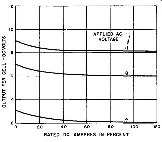
Fig. 5-19. Voltage Regulation of Single Phase, Selenium, Bridge-Rectifier
on Resistive Load.

Fig. 5-20. Voltage Regulation of Single Phase, Selenium, Bridge-Rectifier
on Battery Load.
At full rated output and at normal temperature (35 degrees Centigrade) the voltage regulation of the selenium rectifier feeding a resistive load is 10 to 15 percent. About half of the output voltage regulation occurs from zero to 20 percent load; this makes possible good regulation of 5 to 10 percent over 80 percent of the load range.
If the voltage regulation requirements are critical, then the rectifier can be selected so that normal operation is se cured between 20 and 100 percent load. This can be done by obtaining a rectifier for the application, having the proper electrical capacity so that the minimum load on the rectifier will be about 20 percent. If the mm1mum load is below 20 percent and close voltage regulation is necessary, the minimum load may be artificially boosted by an auxiliary constant load.
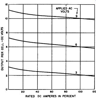
Fig. 5-21. Voltage Regulation of Three Phase, Selenium, Bridge-Rectifier
on Resistive Load.
Fig. 5-18 displays the voltage regulation curve for a selenium rectifier cell on single and three-phase circuit. Ex tended loading is used to clearly show the flatness of the regulation beyond the 20 percent load.
Fig. 5-19 presents the voltage regulation curves for a single-phase selenium bridge rectifier feeding a resistive load.
Three different values of applied AC input voltages are shown.
Fig. 5-20 gives the voltage regulation curves for the same rectifier feeding a battery load.
Fig. 5-21 illustrates the voltage regulation of a three phase bridge rectifier feeding a resistive load. The three curves represent three different values of AC voltage applied per cell. The voltage regulation of a three-phase rectifier on battery load is so close to that of the resistance load of Fig. 5-21, that this graph can be used for either type of loading.
With an inductive load, the regulation is dependent on the ratio of inductance to resistance and is generally higher than with a resistance load. In the case of the three-phase circuit the regulation is about 10% regardless of the type of load.
Efficiency
The selenium rectifier is a resistive device at power frequencies and so has electrical losses in operation which make 100 percent efficiency impossible. The efficiency of the selenium rectifier is a function of its combined losses--that due to the forward and the leakage currents. In the form of an equation the efficiency may be expressed as:
Efficiency in %= DC output volts x DC output current
DC output volts x DC output current + WF + WR where WF = loss in watts due to forward current.
WR = loss in watts due to leakage current.
These electrical losses in the forward and reverse direction are the I^2R losses in the forward and reverse direction.
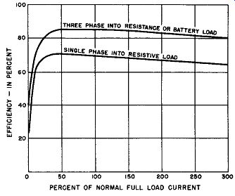
Fig. 5-22. Typical Efficiency Curves of a 26 Volt Selenium Rectifier Cell
Operating at Full Voltage.
The loss associated to the reverse direction is practically constant if the applied voltage is constant. The loss in the forward direction behaves in a peculiar manner resulting in high and constant efficiency for rectifier loadings from 20% to 100% of full load. This constant, maximum efficiency over the wide range results because of the non-linear variation of the forward resistance with current in the selenium rectifier.
Because of this, the forward electrical losses do not increase in direct proportion to the square of the forward current, as would be the case if the rectifier were a linear resistance de vice. It is correct that the forward electrical losses of the selenium rectifier are still equal to I^2R, but R (the forward resistance) decreases with increasing forward current causing the product I^2R (representing the forward electrical losses) to increase at a diminishing rate. Thus, the efficiency remains practically constant over the wide range of 20% to 100% of full load.
Fig. 5-22 shows the efficiency performance of the selenium rectifier operating at full voltage. The lower curve is that of a rectifier feeding a resistive load and operating from a single-phase circuit. The upper curve is that of a selenium rectifier feeding either a resistive load or a battery charging load and operating from a three-phase circuit. In the first case the efficiency is 65 to 70% over the wide range of 20 to 300% of full load current. In the second case the efficiency is 80 to 85% for the same wide range. The selenium rectifiers used to obtain these curves had normally spaced stacks. The 100% or normal full load current is the rated current for a rectifier assembled with such standard cell spacing.
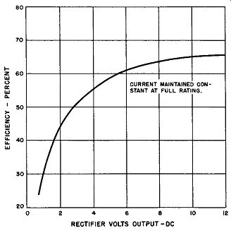
Fig. 5-23. The Efficiency of a Single-Phase Selenium Rectifier is a function
of Output Voltage and Current.
Increasing the cell spacing on the rectifier stack or adding cooling fins to the stack permits increasing the amount of current that the rectifier will carry for the same temperature rise. The continuous duty rating for stacks which employ extra spaced cells or cooling fins may be increased up to 250% of the normal full load current rating.
As can be seen from the efficiency curves of Fig. 5-22, the main effect of increased current over the 100% full load condition is a reduction of the efficiency and also poorer voltage regulation.
Statements concerning efficiency should specify the particular voltage and current at which the rectifier is operating.
For example, Fig. 5-23 shows the change in efficiency that takes place as the output voltage is varied and the current load maintained at 100%. In general, a single-phase full wave rectifier operating into a resistive load will have an efficiency at rated output of 60 to 70 percent. In a similar circuit with a battery charging load, the efficiency will be from 70 to 75 percent. In three-phase operation, efficiencies of 85% can be obtained at full rated output for either a resistive or battery charging load.
Power Factor
Power factor, defined as the ratio in percent of the AC watts input to the product of the AC volt-ampere input, is practically unity for the selenium rectifier when it is used on low frequency power sources, such as commercial power lines.
When the selenium rectifier is used in a commercial power circuit, the overall power factor will be determined by other equipment associated with the rectifier. For example, if the selenium rectifier is used with a line-isolating or step-down transformer and feeds a resistive load or a battery on charge, the power factor is usually 90 to 95% or better.
At higher frequencies the inherent shunting capacitance of the rectifier cells alters the power factor to something less than unity--the exact value being a function of the applied frequency and the associated load of the rectifier. This reduction of the power factor for the selenium rectifier becomes pre dominant for frequencies greater than 1000 to 2000 cycles per second.
Frequency Characteristic
The selenium rectifier cell was described previously in this section as comprising two electrodes separated by a semi conductor and a barrier or insulating layer. This causes an inherent capacitance effect for the rectifier cell which becomes apparent at high frequencies. This capacitance of the rectifier cell is similar in its behavior to a small physical capacitor shunted across the perfect rectifier cell. The adverse effect of the capacitance across the rectifier cell is to reduce the reverse impedance. The exact value of this capacitance is a function of the area of the rectifier cell and is roughly 0.1 microfarad per square inch. The value of the capacitance is not constant for a particular cell but depends upon the applied polarizing voltage.
The chief limitation due to this inherent capacitance of the selenium rectifier cell is to restrict the rated characteristics to frequencies below 1000 to 2000 cycles per second.
The selenium rectifiers are required for operation above 2000 cycles per second, they must be especially processed to reduce the shunting capacitance discussed above. The most effective method to reduce the shunting capacitance is to reduce the rectifier cell area. To achieve an economical method of manufacturing small area selenium rectifier cells, small discs are punched from large sheets which are coated with selenium, heat treated, and have the small diameter front electrodes properly masked concentric to the proposed punched area.
These small discs are then assembled into an insulated tube and spring-loaded to maintain the proper pressure upon the discs. Though this type of construction completely encloses the rectifier cells, the heat radiating surface is large in contrast to the effective working area of the cell resulting in a rated current density (amperes per square inch) which is larger than for the open construction described. Of course, the working voltage per cell remains the same. The enclosed type of construction also makes possible compact rectifier assemblies for high voltage application.
Effect of Idleness and Speed of Operation
The barrier layer in the selenium rectifier cell is electrically formed. This forming is part of the manufacturing process and commercial rectifiers are completely formed be fore being sold to the consumer. In use, the formation of the barrier is continually maintained by the normal applied voltage.
In periods of idleness, when no voltage is applied to the rectifier, some degree of formation is lost or the rectifier becomes partially unformed. Upon application of the voltage, however, reforming occurs; this process is normally completed within one or two seconds. The only noticeable effect in operation during this reforming process is a transient increase in leak age current due to the less effective barrier layer resulting from idleness. This transient has no significant effect on the rectifier output.
The speed of operation of the selenium rectifier is instantaneous. A DC output is instantly available as soon as the AC power is applied to the input of the rectifier.
Aging and Life
The operation of a selenium rectifier is considered to be electronic in character and, as long as it is operated with in its voltage, current, and temperature ratings, its life is stated to be indefinite. In commercial circles such rectifiers have been tested under many conditions for tens of thousands of hours. Moreover, in practice, many practical applications of the selenium rectifier have exhibited more than twelve years of trouble-free operation. It is true that if the rectifier has been idle for some time it may show a slight loss of rectification efficiency when the AC power is first applied. Its original electrical ratings are restored within a few seconds after the AC power is applied due to the reforming of the blocking layer.
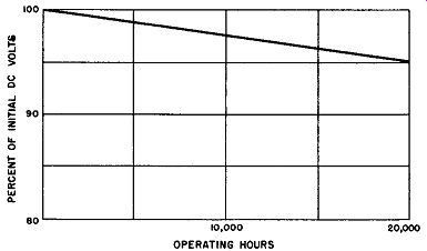
Fig. 5-24. Aging Characteristics of Selenium Rectifiers.
Fig. 5-24 shows a representative selenium rectifier performance aging curve with respect to hours of operation, for a number of rectifier stacks. The rectifier stacks under the test were single-phase bridges feeding resistive loads. An ambient temperature of 35 degrees Centigrade and the electrical ratings of the rectifier stacks were maintained during the tests.
It will be noted that the DC voltage output at the end of twenty thousand hours was about 95% of the initial value. This de crease in output voltage with hours of operation is due to a small increase in the forward and reverse resistance. The increase in the forward resistance, of course, decreases the output voltage; the increase in the reverse resistance improves the rectifier characteristics. If it is necessary to maintain the output voltage constant, then some means to compensate for the increased forward resistance must be provided. One means to accomplish this is to provide additional increments of AC voltage input by having available taps on the supply transformer.
In general, then, selenium rectifiers tend to show a small decrease in the output voltage due to an increase in the forward resistance. This increase of the forward resistance is not progressive but stabilizes after 10,000 to 20,00U hours of continuous service and the net decrease of the output voltage is of the order of 5 to 10%, if the rectifier is kept within its temperature and electrical ratings. The actual time required to reach full stability is a function of electrical loading, the temperature of operation, the circuit type, the duty cycle, or a combination of these factors. Idle rectifiers do not exhibit an appreciable aging effect.
Threshold Voltage
Fig. 5-25 represents the static forward characteristics of a selenium rectifier cell operating at an ambient temperature of 35 degrees Centigrade. It will be noted that approximately 0.4 volt DC must be applied before forward current is observed. Under dynamic conditions, that is, with the cell operating as a half wave rectifier with an AC input voltage, approximately 0.3 volt rms must be applied before forward current is detected in the rectifier load circuit. Thus, the threshold voltage of the selenium rectifier cell is of the order of 0.3 to 0.4 volt depending upon temperature and circuit conditions.
Operating Temperature and Derating
The electrical ratings of a selenium rectifier are specified at an ambient temperature of 35 degrees Centigrade.
Selenium rectifiers are capable of operation over a wide range of temperatures--at a reduction of efficiency and electrical ratings. Over the temperature range of minus 40 to plus 70 degrees Centigrade the percent change in output voltage is held to less than 10%.
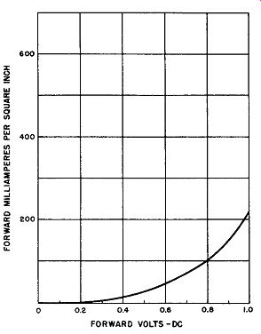
Fig. 5-25. Static Forward Characteristic of a 26 Volt Selenium Rectifier
Cell.
At low temperature operation the forward resistance is increased resulting in a diminishing of output voltage and efficiency. The increase of losses at low temperatures is partly offset by the heat generated in the unit which increases the temperature above the ambient temperature. Selenium rectifiers have been experimentally operated at temperatures as low as minus 65 degrees Centigrade (minus 85 degrees Fahrenheit); after this exposure the forward resistance is permanently increased by 25% and the efficiency at this low temperature is 13% less than at 25 degrees Centigrade.
At the high end of the temperature range, that is, above an ambient of 35 degrees Centigrade, the selenium rectifier cannot be operated at its normal ratings. The output must be decreased in either voltage, current, or both. A typical derating curve for high-temperature operation is given in Fig. 5-26.
To operate in an ambient temperature above 35 degrees Centigrade, the rectifier losses must be reduced so that the safe operating temperature is not exceeded. If the applied voltage is reduced, the reduced leakage losses may permit an increased forward current at an operating temperature above 35 degrees Centigrade. The jags in the current curve of Fig. 5-26 represent this option--for example, if the applied AC voltage to the selenium rectifier is reduced 20% at 50 degrees Centigrade, the current rating may be increased about 5% over the normally diminishing current rating.
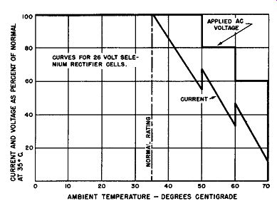
Fig. 5-26. Current and Voltage De-ratlng Curves to Maintain Constant Operating
Temperature for Ambients above 35 Degrees Centigrade.
At an ambient of about 75 degrees Centigrade the average selenium rectifier is derated to zero. The derating curve is based on continuous duty. Better ratings at higher temperatures can be obtained for intermittent operation, the value of these ratings being dependent upon duty cycle.
Ambient Conditions Other Than Temperature
Selenium rectifiers, like most electrical equipment, are sensitive to corrosive dust, moisture, fumes, and tropical conditions. Generally, insulating varnishes protect the rectifier from moisture and dust. Fungus treatment protects it from tropical conditions; and special multiple-layer finishes protect it from mercury vapor, against which the selenium rectifier is particularly weak. One manufacturer of selenium rectifiers warns his customers not to use or store selenium rectifiers where mercury vapor is present.
Future Outlook
Selenium rectifiers were introduced with cell ratings of about 14 volts rms. In less than five years this voltage rating was increased to 26 volts rms. The present effort is to increase the voltage rating to much higher levels of the order of 50 to 70 volts per cell. On a laboratory basis, cells have been developed that operate at 70 volts rms. Besides trying to improve the voltage rating, effort is being expended to extend the upper temperature rating from 70 to 75 degrees Centigrade to 125 to 150 degrees Centigrade. Here the limitation will be the softening temperature of the selenium semiconductor.