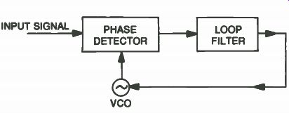
Fig. 7-1. Basic phase-locked loop circuit.
| Home | Audio mag. | Stereo Review mag. | High Fidelity mag. | AE/AA mag. |
We begin this section with a look at the basic phase-locked loop (PPL) circuits. Then comes some additional information on (PLL) and voltage-controlled oscillators (VCO). Information and problem checkouts for one of RCA's direct address remote control tuning systems will be the next item covered. The last section will cover the General Electric remote/ electronic tuning system that uses infrared signals for control. We will be looking at decoder operation, DC voltage-controlled varactor tuning for electronic tuners and much more.
BASIC PHASE-LOCKED LOOP
The basic phase-locked loop has three components:
• A voltage-controlled oscillator (VCO).
• A phase detector.
• A low-pass filter.
Note the basic PLL block diagram in Fig. 7-1.
Fig. 7-1. Basic phase-locked loop circuit.
The phase detector compares the phase of an input signal with the phase of the VCO. Thus the phase detector measures the phase difference of these two input signals. This difference voltage is then filtered and fed into the VCO. The VCO control voltage adjusts the frequency in order to reduce the phase difference between the input signal and oscillator. When the loop is locked in, the control voltage keeps the VCO frequency on the exact average frequency of the input signal. For each cycle of the input signal, there is only one cycle of the oscillator output. Phase-locked loop control is currently used for automatic frequency control (afc) in many electronic equipment applications. With the phase-locked loop technique, exact frequency control can be achieved, while conventional afc circuits have some frequency error.
Most phase-locked loops produce a small amount of control voltage (not zero volts) from the output of the phase detector to maintain lock-in. Thus, the loop operates with some phase error present. In a well designed PLL, this error voltage will be quite small.
If the incoming signal is modulated by phase or frequency, some noise will usually be present. Thus the phase-locked system must reproduce the original signal while filtering out as much noise as possible.
In radio receivers, the local oscillator signal, which is very close to the expected signal, is used for the feedback control. The local oscillator and incoming signal waveform are compared with one another by a phase detector whose error output indicates the phase difference. To suppress noise, the error is averaged over a period of time, and this averaged error is used to control the oscillator frequency.
If the signal is stable, the local oscillator will require very little information to track, and this information can be averaged over a long time period, thus eliminating large noise levels. The input to the loop is usually a noisy signal while the output of the VCO is a cleaned-up version of the input signal. Two things to note about the filter is that the bandwidth can be narrowed and the filter automatically tracks the signal frequency. A narrow bandwidth is capable of rejecting large amounts of noise. These features-automatic tracking and narrow bandwidth-account for most applications of phase locked loops in receivers.
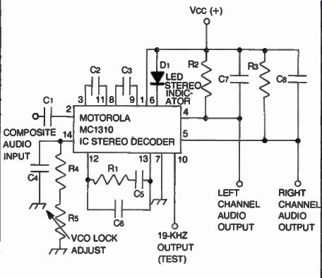
Fig. 7-2. Motorola MC1310 IC stereo decoder (courtesy of Motorola).
MOTOROLA IC STEREO DECODER
AM FM stereo decoder is represented by the Motorola MC130 integrated circuit shown in Fig. 7-2. This is the so-called coiless FM stereo decoder that has seen applications in many consumer electronic products. This same chip will also be found in some modern FM stereo auto radio receivers.
In both types of stereo decoders, you will notice alignment instructions that make use of Lissajous patterns on an oscilloscope to check for the exact 38-kHz frequency. I have found that these checks can be bypassed and you can make use of the capture and lock-in features of the PLL to make these adjustments. The stereo indicator lamp is used to tell us when lock-in occurs.
Oscillator Frequency Adjustment Tips
Adjust the oscillator frequency control until the stereo indicator lamp comes on and stays lighted. Then adjust the main tuning dial of the radio up and down the FM band making sure that the lamp comes on every time a stereo FM station is received. Be sure to check several stations as you tune from above or below the station.
ADDITIONAL PHASE-LOCKED LOOP REVIEW
A basic frequency synthesis (FS) is shown in Fig. 7-3 of the phase-locked loop block diagram. This basic system utilizes the phase-locked loop (PLL) principle in conjunction with a digital frequency programmer to generate a number of discrete frequencies.
Phase-locked loops have been used in a number of electronic applications over the past few years. Some uses include FM stereo decoding, demodulation of FM signals, CB radios, VCRs and TV and FM receiver tuners.
Phase locking is actually a technique of forcing the phase of an oscillator signal to exactly follow the phase of a reference signal.
The PLL automatically locks onto and tracks a signal, even though its frequency changes. The PLL does all this with the help of its phase comparator and a voltage-controlled oscillator (VCO). Specifically, the phase comparator samples the frequency of an input signal with that of a reference oscillator and produces an error voltage directly in proportion to the difference between the two.
For simplicity, you can assume a close relationship between frequency and phase.
The error voltage has two functions. It is fed back to the VCO and changes its frequency to match that of the input signal. This feedback enables the PLL to lock onto and track the signal. The error voltage can also be considered a demodulated FM output since it varies directly with a shift in the input signal frequency.
Simply stated, the error voltage from the phase comparator permits the PLL to lock onto a frequency, and to track it continually over a given range.
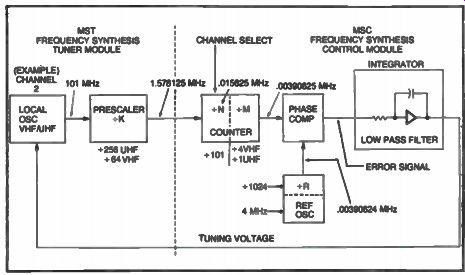
Fig. 7-3. Basic phase-locked loop operation.
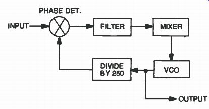
Fig. 7-4. Block diagram of a programmable divider.
CHECKING PLL AND VCO CIRCUITS
The frequency counter is very useful for troubleshooting phase-locked loop circuits. Because these circuits are in a loop configuration, you cannot break the loop for testing purposes and still retain normal operation. Let's consider an actual PLL circuit, the one shown in Fig. 7-4. The problem in this circuit was a wrong frequency out of the VCO. The programmable divider was set to divide by 250, so the VCO output should have been 17.5 MHz (1 kHz X 250 X 10) + 15 MHz. However, the VCO was locked in at 17.4 MHz. Now to solve this loop problem.
A check with the counter and with the VCO locked in indicates that the VCO, phase detector and filter are operating. But with the wrong frequency out of the VCO, chances are that the fault is in the counter string or mixer, so we just move down the string. A check of the mixer shows us an output of 2.4 MHz, which is correct for the mixer output difference between 17.4 MHz and 15 MHz inputs.
Now, we know that the input to the first divide-by-10 stage is 2.4 MHz. A look at its output shows it to be 240 kHz, and a correct division by 10, so the input to the programmable divider is 240 kHz.
Now a check of the programmable divider output shows exactly 1 kHz. This means the programmable divider is only dividing by 240 instead of 250. A recheck of the programmable pins on the LSI chip confirms that it was programmed to divide by 250, but was only dividing by 240. The LSI chip was replaced and the problem was solved.
The above example trouble shows that a good stable frequency counter is now required to troubleshoot these modern digital PLL circuits. Note the Sencore counter setup in Fig. 7-5, one that can be used for PLL checks.
A counter can also be used as a check of phase-locked loop circuits to determine how stable the circuit is and in working to improve stability. The range of flashing of the least significant digits gives a good approximation of circuit stability. The counter is a must in servicing to ensure that design criteria and tolerance have been met.
The counter is also useful in checking instruments or equipment with LC or crystal-controlled oscillators. Crystal oscillators have to be checked for tolerance during alignment or servicing, and using a counter is the best way this can be accomplished.
RCA DIRECT ADDRESS TUNING SYSTEM
As we check out some problems that may occur in this RCA direct address remote system, refer to the PC board layout of the remote control module in Fig. 7-6. Some of these RCA remote control trouble symptoms are as follows:
No or improper channel up/down action.
No or improper add or erase of the scan memory.
No or improper channel change or skip.
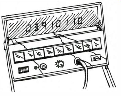
Fig. 7-5. Sencore model FC51 frequency counter used to check a PLL circuit.
Preliminary Checks
Check 'all interface connections and wiring to and from the MSC control module. Each time a channel change is performed, note the display readout. This visual readout indication can be used as an aid for tracking down a particular problem.
No or Improper Channel Up/Down Action
Scan up and down channel data requires that the frequency synthesizer chip (U1) receive proper logic conditions to pins 16 and 17 from the SCAN CHANNEL switch. First, confirm good ground connections at terminal S on the MSC 002 module and to the UP/DOWN switch assembly. If the ground is open, scan capability is lost. If either up or down action is lost, check the terminal on the MSC 002 module for a logic low condition when the CONTROL button is pressed.
No or Improper Add or Erase of Scan Memory
Confirm proper logic conditions at terminals T and U on the MSC 002 control module. Make sure the SELECT-LOCK switch is in the select position and that there is a good ground connection at terminal S or the MSC 002 board. An appropriate add or erase line must go to logic low condition to indicate an add or erase function to the scan memory IC (U4). When add or erase functions are not activated, add and erase lines should be idle at logic high (+5 volts DC).
No or Improper Channel Change or Skip
These problems are usually associated with the MSC module.
Replace control module MSC 002.
FS SCAN REMOTE SERVICE PROCEDURES
The FS scan remote system utilizes a frequency synthesizer chip U2, memory chip U4, and on-screen channel display/clock chip U3. These ICs and associated components make up the MSC 003 tuner control module for the scan remote system shown in the Fig. 7-7 schematic. With this system, we will focus in on the display/ clock interface and remote control servicing procedures.
The scan remote system includes the MCR 003 remote receiver, which also has the remote decoder IC. This IC processes channel up/down, set on/off, and volume up/down information from the remote control unit (CRK 26) via the preamp (MCY 003), and sends appropriate voltage to the MCS 003 control module. The remote receiver also processes function commands from the manual pushbuttons on the set. Also located on the remote receiver is a +11 volt DC regulator (Q1101), which provides DC voltages to the remote receiver and preamp board (as long as the TV receiver has AC power connected). A separate power supply transformer (T1) provides AC power (12 volts) to the regulator Q1101 for standby and operation voltage to the remote receiver and preamp. Relay K1 provides on-off AC power to the receiver.
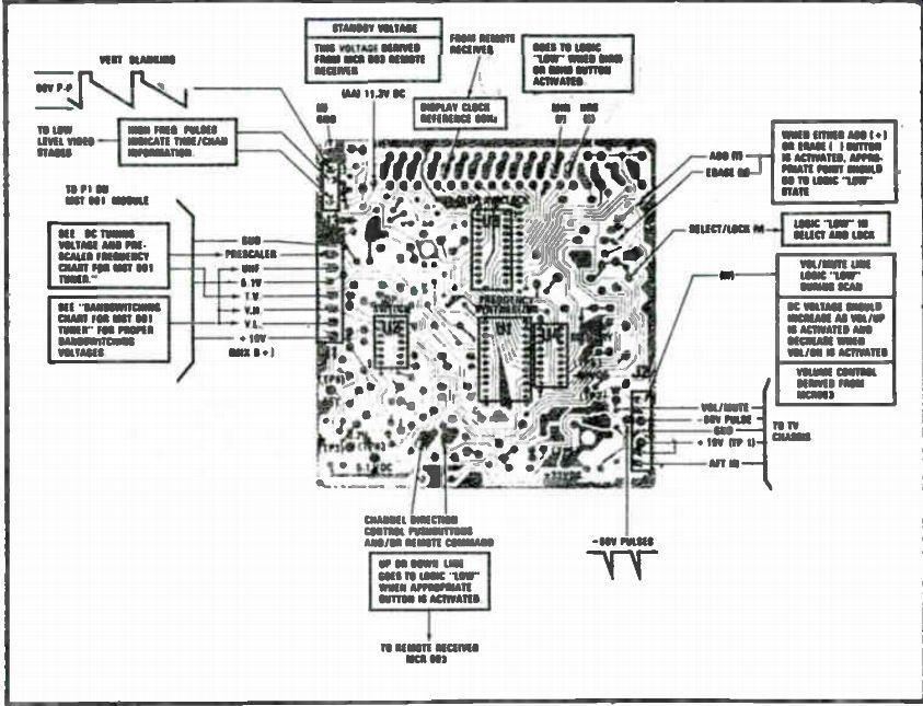
Fig. 7-6. RCA MCS remote control module (courtesy of RCA).
Symptoms and Service Procedures
Use an isolation transformer and disconnect the line cord during all static checks. Use insulated clip leads for dynamic checks.
Check all interface connections and wiring to and from the MSC 003 control module, remote receiver MCR 003 control module, remote receiver MCR 003, preamp MCY 003 and other assemblies within the system.
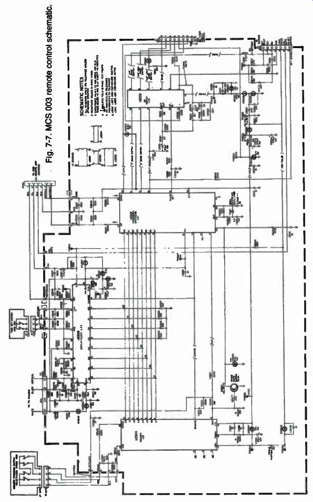
Fig. 7
Unable to Set Time, Erratic Display, or Loss of Time
Display. Display problems can be defined as a loss of, erratic, or distorted on-screen die display with otherwise normal operation.
Such problems are usually confined to the clock and display IC (U2503) located on the MSC 003 control module or to connector problems. If problems described above are encountered, replace the MSC 003 module. A defective display assembly may also cause instrument video problems. If video problems are suspected as being caused by the display system, remove connector P3-MSC and see if the problem clears up.
Failure of the system to maintain the correct time of day will usually not occur without the other symptoms being evident. Check the following if this occurs:
• Note any possible intermittent power interruptions. If power to the set is interrupted, the time displayed will be lost when power is restored, requiring the clock to be reset.
• Check the TIME-SET switches and cabling for possible intermittent connections.
No Channel-Up/Down. Check the connections between the remote receiver and preamp. Monitor the logic condition at pins 9 and 11 of U1101 on the remote receiver module. These should go low when the CHANNEL button is depressed. If the logic condition does not change, the problem may be a defective component or remote receiver board. Check for +11 volts DC to the IC (U1101) and preamp board MCY 003.
If the MSC responds to remote control channel up/down, but does not respond to manual channel up/down, check the connections between the remote receiver and the manual button assembly. Check the logic conditions at X and Y on the MSC 003 control module. If proper logic conditions are not present on the MSC board, replace the MCR 0(X, remote receiver. If the correct logic levels are found on the MSC 003 and you do not get the correct command function, replace the MSC 003 control module.
No or Improper Volume Up/Down. Check for good connections at the remote receiver and preamp. If the connections are OK, replace MCR 003 remote receiver.
Now check for proper connections at J1101 and P1101. If the problem still exists, replace the MCR 003 remote receiver. No or improper volume up/down in remote or manual operation usually indicates a problem associated with the remote decoder IC (U1101), or a problem associated within the TV sound section.
First, monitor the DC voltage at point W on the MSC 003 module.
Now push the VOLUME UP/DOWN buttons and confirm that the DC voltage tracks when the appropriate button is pressed. If the voltage does not change, replace the MCR 003 modules.
No Remote Control Action (Manual Operation OK). This type problem usually indicates a fault in the CRK-26 transmitter MYC 003 preamp or the MCR 003 remote receiver unit. Check the battery in the remote hand unit. Test for proper mode frequencies of the hand remote unit by connecting the frequency counter to J1103-4 on the MCR 003 remote receiver. The frequencies should be as follows:
Volume up-42.15 kHz.
Volume down-40.55 kHz.
Channel up-39.10 kHz.
Channel down-37.70 kHz.
This also confirms that the preamp (MCY 003) is working properly.
Confirm the presence of +11 volts DC on the MCR 003 module. If the manual tuning operation works properly, the remote decoder IC is receiving +11 volts. A good place to check the +11 volts is at point AA on the MSC module. If all of these check out replace the MCR 003 module.
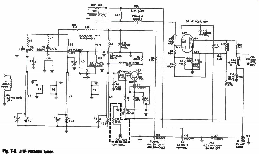
Fig. 7-8. UHF varactor tuner.
No On/Off Action From Either Remote or Manual Buttons. On/off problems are usually confined to faults on the MCR 003 remote module. AC power for the TV is via a switching relay circuit, which is also located on this remote module.
Listen for the on/off relay K1 click. This will indicate if the control winding is receiving the DC control voltage for proper on/off operation and probably the remote receiver is good. If the relay does not click, check the DC voltage at TS-1101-1 on the remote receiver. If the voltage here tracks up and down as volume up and down is activated, the problem is in relay K1. Voltage at TS 1101-1 should be approximately 1.5 volts minimum for proper ON operation with no volume. If the voltage tracks at TS 1101-1 and the set does not come on, jump pin 1 to 2 of plug Pl on the MCR to restore AC power to the receiver. This step bypasses the MCR 003 remote circuit.
--------------------
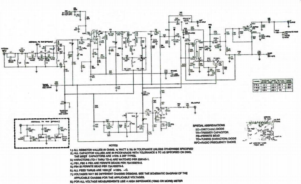
Fig. 7-9. VHF varactor tuner.
------------------
GENERAL ELECTRIC REMOTE/ELECTRONIC TUNING SYSTEM
This GE system uses some of the most recent advances in digital electronics and microcircuitry plus selection of all 82 TV channels. The remote control operates via pulsed a invisible light beam (infrared) signals. This makes the system immune to some types of false triggering which might occur with uncoded ultrasonic systems.
The many TV electronic tuning systems in use today are similar in many respects. All, for example, depend on the varactor tuner for actual channel selection, and all use electronic circuitry to control the varactor tuner. Electronic tuning systems, however, vary widely in technology, principles of operation and complexity.
The GE electronic tuning system has modular units and incorporates plugs and connectors to make troubleshooting easier.
In this system, channel selection is precise to the degree of not requiring any FINE TUNING control. The channel selection is simplified as the system acts only on the last two channel digits entered. Multiple channel number entries are ignored, except for the last two digits.
The block diagrams in Figs. 7-8 and 7-9 show the overall GE electronic tuning system. The block diagrams show the inputs, outputs and B+ points for the various components in the system.
Even though highly complex electronic processes take place within the modules, their outputs are mainly in the form of DC voltages.
For this reason, much of the troubleshooting can be performed with a volt-ohm meter.
The remote receiver module detects the infrared signals from the hand control unit, amplifies them and connects them to the remote decoder module. The remote decoder module also receives inputs from the front panel ON/OFF/VOLUME control assembly.
The remote decoder module decodes the commands from the remote receiver and on the ON/OFF/VOLUME controls and translates them into voltages and logic states.
The remote decoder module outputs are as follows:
• A DC voltage that activates the on/off function of the TV.
• A DC voltage that controls volume level.
Various logic states that initiate channel selection.
A +5 volt source is used in the tuner control module to power the circuitry that remembers the received channel before the set was turned off. The tuner control module provides DC controlling voltages to the UHF and VHF tuners and is connected in a closed loop configuration with the tuners. It samples the local oscillator frequencies from the tuners and develops the DC voltages required for channel selection. This unit also provides the logic to program the channel selection. This unit also provides the logic to program the channel number readouts. The electronic tuning system also contains an ON/OFF module that controls AC power to the main power supply of the TV.
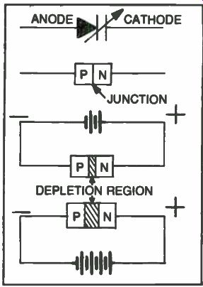
Fig. 7-10. Varactor capacitance change effect.
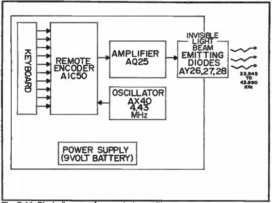
Fig. 7-11. Block diagram of a remote transmitter.
Electronic Tuners
The VHF and UHF tuners utilize varactor diodes to perform the frequency changes necessary for channel selection. The varactor diode is a semi-conductor that can be used as a variable capacitor. The change in capacitance exhibited by the varactor diode is caused by the effects of reverse biasing the device with a DC voltage. Figure 7-10 illustrates this capacitance change effect.
When reverse bias is applied to the varactor diode, its charge carriers are attracted away from their normal P-N junction. A DEPLETION REGION develops in place of the P-N junction, forming-in effect-a dielectric. The P and N material of the varactor diode serve as capacitor plates. With a small amount of reverse bias applied, capacitance is large, because the dielectric (depletion region) is thin. As more reverse bias voltage is applied, capacitance decreases because the depletion region and, hence, the thickness of the dielectric is increased. You may recall that capacitance is inversely proportional to the thickness of the dielectric.
The varactor diodes in the tuners are combined with inductance to form tuned circuits. Thus, with varactor diodes, the tuned circuits in the tuners are voltage controlled. Changes in the DC tuning voltage fed to the tuners thus change the frequency that the tuners select.
Remote Transmitter
The remote transmitter, shown in Fig. 7-11, produces frequency-coded infrared signals. The hand unit keyboard is connected directly to the inputs of the dedicated IC, AlC50, which is the remote encoder. The remote encoder IC produces a different frequency for each remote function. These frequencies, in the range of 33.945 to 43.990 kHz, are amplified and used to modulate infrared light-emitting diodes. A crystal-controlled oscillator provides the frequency reference for the AlC50.
Fig. 7-12. Block diagram of a remote receiver.
Remote Receiver Module
In the remote receiver, shown in Fig. 7-12, a light-sensitive diode is used to detect the infrared beam. Before reaching the diode, the beam first passes through a filter that eliminates virtually all visible light and passes most of the infrared signal. After detection, the pulse-coded information is amplified by a bandpass amplifier and then connected, via a shielded cable, to the remote decoder module.
Remote Decoder Operation
The remote decoder module, shown in Fig. 7-13, controls multiple receiver functions. This module first decodes the amplified intelligence that originated in the remote transmitter. From this and the other inputs, it provides the voltages and logic states needed to control the on/off, volume, and remote channel selection processes of the receiver.
The frequencies received from the receiver module are first processed through a bandpass amplifier and then fed to the input of a specialized IC, DIC50, the remote decoder. The remote decoder IC is referenced to a crystal-controlled oscillator. The oscillator provides the decoder with the same frequency reference as its matching counterpart, the encoder chip in the remote transmitter.
The remote decoder translates the frequencies received at its input into output voltages and logic states.
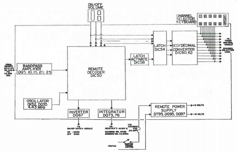
Fig. 7-13. Remote decoder module.
Fig. 7-14. Hobbyist adjusting 5V supply with a digital voltmeter.
For channel selection logic, all frequencies related to transmit ted commands are received by the remote decoder at its input.
They exit the chip in the form of 4-bit binary logic. Some of the output pins carry logic information used for the input pins. This is not uncommon in microcircuitry design, as there is a need to limit the number of pins on complex logic chips. The remote decoder IC differentiates on/off/volume commands and channel selection commands by using an extra bit of logic to identify channel number logic. The extra bit activates DIC58, which allows the remaining channel number processing circuitry to identify the binary logic as a received channel number. When on/off/volume commands appear on the input/output pins, the extra bit is not present and the processing circuitry ignores the command, thus preventing its mis interpretation as channel number logic. The remaining circuitry of the remote decoder, DIC54, 60 and 62, converts the multiple pulsed binary channel number logic into single pulsed decimal logic.
Power Supply Information
The power supply module develops its voltages from an external transformer and diode rectifiers. Two of the sources, +5 and +6.8 volts, are regulated. Figure 7-14 shows a hobbyist adjusting the +5 volt supply with a DVM. Also, a +22 volt source required by the electronic tuning system is obtained from the main TV chassis power supply.
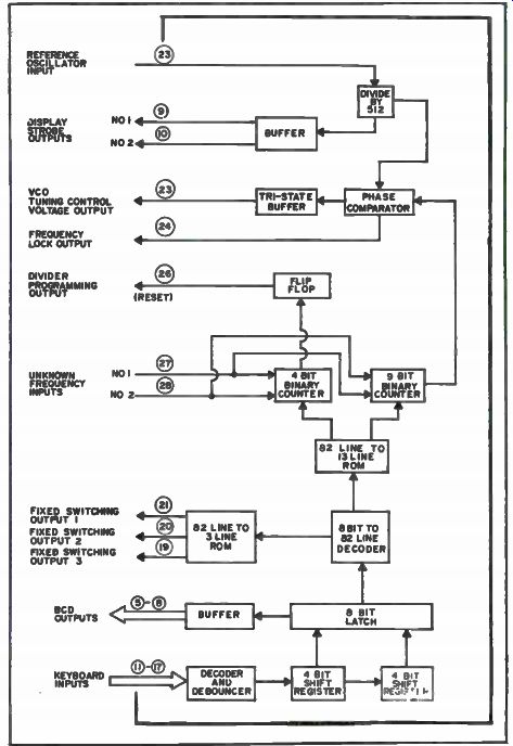
Fig. 7-15. Block diagram of an NC 6410 chip.
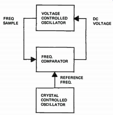
Fig. 7-16. Basic phase-locked loop circuit.
Tuner Control Module
The tuner control module accepts channel selection logic in puts from the keyboard of the TV and the remote decoder module.
The primary outputs are DC voltages that activate either the UHF or VHF tuners that switch between VHF high and low bands, and perform channel selection in the tuners. The heart of the tuner control module is the frequency synthesizer chip. A block diagram of the NC6410 IC is shown in Fig. 7-15.
The phase-locked loop, block diagrammed in Fig. 7-16, consists of three stages. These are a highly stable crystal-controlled oscillator, a frequency comparator and a voltage-controlled oscillator. The frequency comparator accepts two inputs, the reference sample from the voltage-controlled oscillator and a frequency sample from the voltage-controlled oscillator. It produces one output, a DC voltage that controls the frequency of the VCO. In operation, the DC voltage forces the VCO to run at exactly the same frequency as the crystal-controlled reference oscillator. Should the VCO drift or change frequency the deviation would be detected by the frequency comparator and its DC voltage would either increase or decrease, changing the frequency of the VCO back to the exact frequency of the crystal-controlled oscillator. Thus, the basic phase-locked loop demonstrates that a voltage-controlled oscillator can be made to run at an extremely stable, reference-determined frequency.
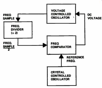
Fig. 7-17. Modified phase-locked loop.
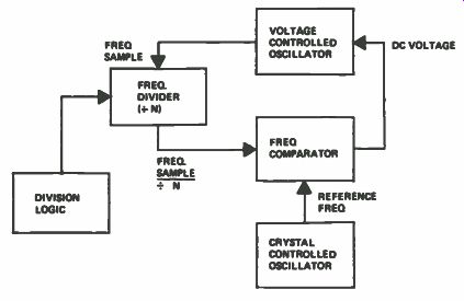
Fig. 7-18. Basic frequency synthesizer.
To see how the phase-locked loop system works in TV tuning systems, we must modify the basic circuit, as shown in Fig. 7-17.
Now, a frequency divider stage has been added to the loop between the voltage-controlled oscillator and frequency comparator. In Fig. 7-17, the frequency divider shown is a divide-by-two circuit. This means that the frequency sample reaching the frequency comparator is now only one-half the frequency of the crystal-controlled reference. Thus, the DC voltage from the frequency comparator will increase or decrease until the voltage-controlled oscillator runs at twice the reference oscillator frequency. When the voltage controlled oscillator frequency sample reaches the frequency comparator, it again matches the crystal-controlled oscillator reference frequency and the loop is stabilized. Thus, the VCO is now operating at twice the frequency of the crystal-controlled oscillator.
Let's now study Fig. 7-18 as we dig into these tuning systems a little deeper. In Fig. 7-17, the divide-by-two stage has been re placed with a divide-by-N stage. The frequency divider in Fig. 7-18 is therefore capable of dividing the VCO frequency sample by multiple numbers of division. With the reference frequency known, the divide-by-N stage can be programmed by logic circuitry to divide by the number of divisions that correspond to specific VCO frequencies. The circuit now becomes a frequency synthesizer, capable of producing a wide spectrum of VCO frequencies, all referenced to one crystal-controlled oscillator and, thus, extremely stable. For example, if the reference oscillator frequency were 1 MHz and we wanted the VCO to run at the correct local oscillator frequency for channel 2 (101 MHz), the logic circuitry would program the divider circuitry to divide the frequency sample by a factor of 101 times.
In the actual circuitry of the tuner control module, the reference oscillator consists of discrete, crystal-controlled components.
The programmable divider is a high-speed IC that has the division logic and frequency comparator contained in the NC6410 chip. The VCO, of course, corresponds to the local oscillators in the VHF and UHF tuners.
The tuner control module block diagram is shown in Fig. 7-19.
The frequency synthesizer, EIC20, accepts three types of inputs.
One is a 4-MHz reference frequency from the reference oscillator stage composed of EIC50 and EX50. Another frequency sample is received from the local oscillators in the VHF and UHF tuners. It also receives channel selection logic from the remote decoder module and front panel keyboard.
The frequency sample from the tuners is first amplified by three transistor stages-EQ1, 2 and 3. It is then divided by a factor of 64 by EIC1. Finally, the frequency sample is divided again by a programmable divider stage-EIC5, 10 and then by 15.
The number of divisions performed by the programmable divider is determined by commands from EIC20. The division commands, in turn, are developed in EIC20 from the channel selection logic it receives.
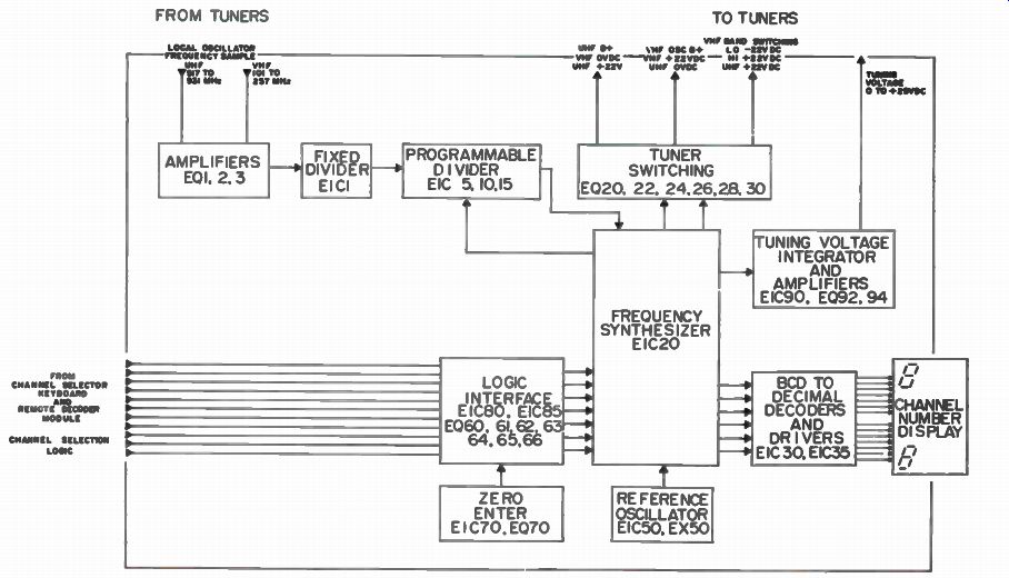
Fig. 7-19. Block diagram of a tuner control module.
Fig. 7-20. Logic probe check on a microprocessor chip.
The channel selection logic entering the tuner control module is first processed before entering EIC20. The logic interface circuitry, EIC80, 85 and EQ60 through 66, convert the decimal logic into a seven-fine code, acceptable to EIC20. In addition, the logic interface circuitry provides impedance matching to the inputs of the frequency synthesizer.
Outputs from the frequency synthesizer are DC voltages that control the tuners and binary-coded decimal logic that is used to develop channel number indication. The tuner switching stage receives commands from the EIC20 as a result of the channel selection logic fed into the chip. Switching voltages are produced which activate either the UHF or VHF tuner with B+ voltage. A VHF high/low bandswitching voltage is also generated in the tuner switching stage.
The DC tuning voltage, fed to the local oscillators and other tuned circuits in the tuners, is developed in the circuitry composed of EIC90, EQ92, and EQ94. This voltage is dependent on the frequency synthesis process.
The final output from the EIC20 chip is binary-coded decimal information that corresponds to the channel number selected. The hobbyist shown in Fig. 7-20 is checking these binary bits with a logic probe. This data is converted first to decimal and then to seven segment logic by EIC30 and EIC35. These outputs drive the LED channel numbers.
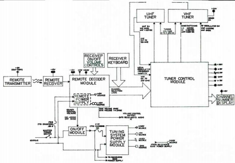
Fig. 7-21. Block diagram of the electronic tuning system.
System Troubleshooting
Some of the MOS digital devices used in this remote system can be damaged by static charges, so when troubleshooting these MOS circuits, special precautions must be taken. Because MOS devices will not leak off static charges, their handling is much more critical than other ICs. MOS devices are usually packaged in conductive foam material. When handling an MOS device, you should touch a grounded object to discharge body capacitance before touching a MOS component. When soldering around a MOS device, the tip of the iron should be grounded. Of course, a static-sensitive component should not be inserted or removed from the circuit with the power on. With electronic tuning systems, this means that the power cord should be unplugged before any modules are replaced.
Remember that most of the power sources of the tuning systems still operate, but the set is only turned off.
Locating defective modules in the tuning system is usually quite easy, because of the nature of digital circuitry. Digital logic circuitry lends itself to analytical analysis far more readily than most analog circuitry. Faults usually give positive indications. A circuit either works right or it will not operate at all. The marginal failure condition, so many times encountered in analog TV sets, is a rare bird in digital logic systems.
The technique becomes apparent when we put this into actual practice. Note the block diagram shown in Fig. 7-21. In one example, the TV set has no volume control with its manual controls, but volume control was normal when the remote control was used. If all other remote functions perform normally, then two areas should be checked out: Either the remote decoder module is defective or the ON/OFF VOLUME control unit and plug connections of the set are faulty. Use an ohmmeter to check controls.
For another example, stations cannot be selected with the remote transmitter and all other controls are operating correctly. A block diagram analysis reveals that the remote decoder module would be the suspected area.
Naturally, some failure modes do not lend themselves to this type of troubleshooting logic. For instance, the receiver may have a no raster and loss of sound symptom. This condition requires choosing between the remote decoder module, on/off module, TV chassis fault and power supply troubles in the main TV chassis. A combination of observations and DC voltage checks is necessary to correctly diagnose the defective module for this type of malfunction.