Crystal Oscillator
For truly precise and stable frequency generation there is no substitute for a crystal-controlled oscillator. At one time crystals were expensive and difficult for the amateur to obtain, but nowadays many are cheap and readily available from normal component suppliers. Crystals do not readily lend themselves to the design of tune-able oscillators, as they can only be pulled a fraction of a percent from their nominal frequencies, but this very fact makes them ideal for the accurate generation of spot frequencies. Often the required frequency will be available "off the shelf', and where it isn't it can often be generated with the help of a divider IC. A problem for the amateur is that often the full information regarding the crystal to be used is not available. Since crystal characteristics vary quite widely, this can make the design of oscillators using discrete amplifying devices such as FETs and bipolar transistors a bit of a hit and miss process. For this reason these will be avoided in this guide, and the most basic designs shown will be those using inverting gates in CMOS devices to provide the necessary gain. Some fully integrated "power up and go" oscillator ICs will be described, as these are the simplest and most reliable method of generating an accurate frequency. These have built-in programmable dividers, allowing several frequencies to be obtained from the one IC with clean, buffered squarewave outputs.
One further device that will be described is the Harris HA7210, a fairly recent introduction to the market. This is a sort of "halfway house", in that it uses an external crystal but can be easily programmed to the optimum internal circuit configuration for various frequencies, and it has a number of other features for low power consumption and reliable, stable operation.
Single-gate Crystal Oscillator
This is one of the cheapest ways to construct a crystal oscillator, using a single inverting logic gate. As mentioned in the introduction it may not always work due to the variable characteristics of crystals, but it is more likely to operate correctly than its discrete transistor and FET equivalents. It can be especially useful with 32.768kHz "watch crystals". Some optimization of component values is usually needed, so an oscilloscope should be available to check operation and wave forms.
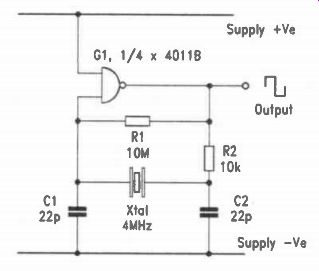
Fig.6.1. Basic Single-gate Crystal Oscillator.
The version of the circuit shown in Figure 6.1, uses one of the four NAND gates in a CMOS 4011B. It is similar to the LC Colpitts circuit in that the capacitors C1 and C2 provide a "tap" to give a 180 degree phase shift from amplifier output to input, which adds to the inversion provided by the gate to give the positive feedback necessary so that oscillation can take place.
Resistor R2 is chosen to adjust the drive to the crystal to a reasonable level and with C2 it also forms a low-pass filter to encourage oscillation to take place at the correct frequency instead of a higher "overtone" frequency, as can sometimes occur. The high value resistor R1 provides DC negative feed back to bias the gate into an active amplifying condition and maintain this.
The values of capacitors C1, C2 and resistor R2 will generally need adjustment to suit the characteristics of the particular crystal in use. With a pair of 22pF polystyrene capacitors and a 10k resistor for R2 the prototype circuit worked well with a 4MHz crystal from the author's "junk box", but two different types of 100kHz crystal required 100pF and 2200pF respectively for C2. Increasing the value of the capacitors will lower the frequency slightly, and a variable "trimmer" is often used for fine tuning adjustment, though it should be appreciated that the degree of variation that can be obtained in this way is very small, usually less than 0.1%. Inspection of the waveforms at the output of the gate and the two ends of the crystal will usually reveal any problems. The gate output will normally be a squarewave, although due to the output impedance of a CMOS device there may be some distortion caused by the load. Parasitic oscillation, indicated by multiple glitches at the crossing points, may indicate a need for higher values of C2, R2, or perhaps both. The input side of the crystal, driven through R2, may have anything from a distorted squarewave through a triangle wave to something approaching a sinewave. The important point is that it should not have a large content of frequencies higher than that intended. The output side, to C1 and the gate input, will usually have a cleaner sinewave although this may be difficult to check as this part of the circuit has a high impedance and can be adversely affected by loading from the test equipment used. A "x10" probe, perhaps with a small DC blocking capacitor, may help here.
This circuit usually works well with "watch crystals". These are sometimes referred to as "tuning fork" crystals because of the shape to which they are cut to achieve low frequency in a very small size, although this cannot be seen as they are always totally enclosed in metal cans. Their frequency is 32.768kHz which, when divided by 2 to the power of 15, results in a 1Hz signal for timekeeping applications. A problem with these crystals is that they are intended for use with circuits powered from just 1.5 volts, so driving them from outputs supplied with much higher voltages can result in failure. They need very little drive anyway, so the value of R2 should be raised to 100k.
In tests, a couple of crystals obtained from a major component supplier withstood a supply of 15 volts, but others taken from defunct watches and clocks have failed even with 5 volts. For reliability the best course is probably to purchase the crystal from a regular supplier and restrict the supply to 5 volts.
Otherwise, it may be worth operating from just 3 volts, as the circuit will still operate from this with a "micropower" supply current. C1 and C2 should normally be somewhere between 10pF and 22pF, and making one of them, usually C2, adjustable allows accurate frequency adjustment for timekeeping applications.
Any of the usual inverting gates can be used with this circuit.
Where a 2-input gate is used, one of these can be tied to an appropriate supply rail as shown to reduce loading on the crystal. Other gates in the same IC could be used for output buffering or gating. Crystal oscillators are usually rather slow to start up due to the very high "Q" of the crystal, so where the signal is to be started and stopped rapidly it is better to keep the actual oscillator running and gate the signal elsewhere.
This is a general purpose circuit that may be useful in some simple applications, but for a circuit needing a divider, or total reliability, some of the following solutions may be better.
A 4060B Crystal Oscillator
One of the gates of the internal oscillator inside a 4060B can be used to construct a crystal oscillator, and the IC will then provide a number of frequencies from the outputs of the internal binary divider. As only one of the two oscillator gates is required a buffered output with oscillator frequency can be taken from the other, which may be useful when testing or set ting up the circuit. Figure 6.2 shows the circuit, using pin 10 as the output to drive the crystal through 100k resistor R2, and pin 11 as an input for the feedback. DC negative feedback to maintain the gate in its active region is applied through R1, and the buffered output of oscillator frequency is available from pin 9. The "reset" pin 12 should be permanently tied to negative supply.
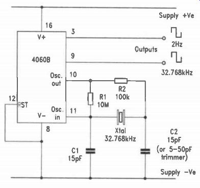
Fig.6.2. 4060B Crystal Oscillator.
Most of the comments relating to the previous single-gate oscillator apply to this circuit. As it is specifically intended for operation in a linear mode as an oscillator, the gate between pins 10 and 11 is less prone to spurious oscillation and glitches than most single CMOS gates. It will work with a variety of crystals, but the value of R2 and the two capacitors will need to be chosen to suit these. A frequency of 4MHz was readily achieved using 10k for R2 and two 22pF capacitors. A watch crystal can be used as before, using a 100k resistor for R2 and fine tuning it by varying the value of C1 or C2, usually C2 which can be a 5-50p trimmer. Any of the available divider outputs can be used, but with a 32.768kHz crystal the final output, from pin 3, gives the oscillator divided by 2 to the power of 14, which is 2Hz. Sadly, it is impossible to obtain a 1Hz signal without using another IC for the single extra divider stage, but where this is done some extra circuitry can be added for generating any other frequencies needed such as 30-second or 1-minute pulses. Note that some dividers do not allow access to the outputs of the first few stages. One that does is the 7-stage 4024B. Some interesting observations regarding supply current were made during the testing of this circuit. The operation can be "micropower", but is not necessarily so as the supply current is heavily -- and non-linearly -- dependant on voltage. The circuit worked down to 2 volts, and at 3 volts drew just 10µA. At 5 volts this rose to 50 uA, and at 10 volts it was half a milliamp! Perhaps the most suitable application for it would be as a micropower frequency source using just two small 1.5 volt cells. However, for a more versatile and reliable micropower source, the specialized oscillator IC to be described next may be a preferable choice.
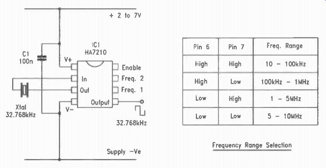
Fig. 6.3
The Harris HA7210 Crystal Oscillator IC
This is an inexpensive and versatile IC which provides a useful design option halfway between discrete crystal oscillator circuits and fully integrated oscillator ICs containing their own on-board crystals. It can be optimized for use with crystal frequencies from 10kHz up to 10MHz, has a special mode for very simple use with watch crystals, works from supplies between 2 and 7 volts, and offers output signal gating. In addition, it is a CMOS device with the typically low power consumption of this family; in fact with a watch crystal and a low voltage sup ply it will operate with a drain of less than 10pA, allowing literally years of operation from a couple of small 1.5 volt cells.
The connections for the 8-pin DIL version of the IC are shown in Figure 6.3, which is also the simplest circuit configuration for a low-frequency crystal. The supply is connected to pin 1 (positive) and pin 4 (negative). The recommended supply voltage is from 2 to 7 volts with an absolute maximum of 10 volts.
This allows the use of unregulated batteries with between 2 and five 1.5 volt cells, whilst a regulated 5 volt supply is ideal.
Direct connection to a 9 volt battery is inadvisable, but where a PP3 is to supply the circuit a cheap and simple solution is the inclusion of four silicon diodes, such as 1N4148's, in series with the positive supply to pin 1. The total voltage drop across these will reduce the supply to a safe value without incurring the additional current that would be taken by a regulator and it's cheaper too! Note the provision of capacitor C1. The manufacturers recommend that a 100n decoupling capacitor is always provided, as close to the supply pins as possible. A ceramic or polyester type should be used for this.
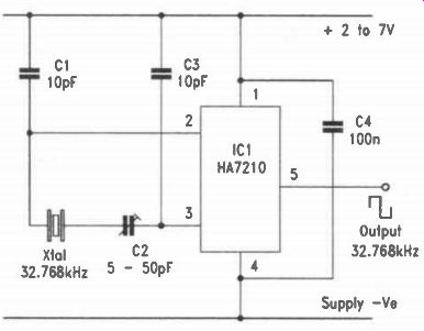
Fig.6.4. HA7210 With Trimmer Adjustment.
The HA7210 has four operating modes to provide optimum conditions for crystals of various frequencies. These are selected by connections made to pins 6 and 7. The table in Figure 6.3 shows these, where "high" means the pin is positive and "low" means it is connected to negative. The "enable" connection to pin 8 can be used to inhibit the output. As it does not stop the oscillator, instant start-stop signal gating is available. These three pins have internal "pull-up" resistors so if they are left unconnected they will assume the "high" state automatically.
The output is available from pin 5, and though the data states that it can drive two CMOS inputs, it can probably manage more than this as loading with a 10k resistor to either supply rail causes only a tiny drop in amplitude. Whilst disabled by pin 8 the output goes to a high impedance state, so a pull-up or pull down resistor may be needed in some applications.
The first of the four frequency ranges, 10 to 100kHz, is intended mainly for use with 32.768kHz watch crystals. In this mode two internal 15pF capacitors are switched into circuit to provide an arrangement similar to that of Figure 6.1, and the internal power supply to the oscillator stage is reduced to about three volts to prevent overdriving of the crystal. In this mode the device can be operated with no external components apart from the supply decoupling capacitor and the crystal connected across pins 2 and 3, whilst the output, buffered and level-shifted into a rail-to-rail squarewave, is available at pin 5. For operation in this mode no connections are necessary to pins 6, 7, or 8. Whilst this may be accurate enough for some applications, where the circuit forms part of a clock or timing system frequency trimming may be needed for precise adjustment. This can be done with the addition of two fixed capacitors and a trimmer as shown in Figure 6.4, which will allow accurate set ting with most watch crystals. Note the unusual connection of the two fixed capacitors to the positive supply rail rather than the negative; this is recommended by the manufacturer. Once set up, the circuit is remarkably stable as the IC compensates for supply voltage and temperature variations and automatically adjusts the crystal drive amplitude to a suitable level.
For other frequencies the appropriate range can be selected with pins 6 and 7 and the crystal simply connected across pins 2 and 3. Where the crystal frequency is on the borderline between two modes, for example 1MHz, both could be tried.
The makers suggest that the higher frequency mode may often be preferable in such cases. Usually the oscillator will operate without problems, even with the odd selections of old crystals often found in experimenters' junk boxes. It probably offers the simplest and most reliable way to construct an oscillator for use with an external crystal.
A few precautions should be observed when using the HA7210 device. The first concerns its name! The DIL package of the one used in testing these circuits bears the marking "HA72101P". The "I" in the suffix can be mistaken for a "1", and in fact has led a leading supplier to list it in their catalogue as the "HA72101". No doubt this will eventually be corrected but, for the time being, if it isn't listed under the first number, try the second! Next, this is a CMOS component so the usual handling precautions should be observed. Although it is relatively cheap, it is still painful to lose around £2.00 by forgetting to use an earthing wrist strap. The output waveform probably won't have a 50:50 duty cycle as this varies with supply voltage and frequency. In many applications this will not matter, but designers should be aware of it for those where it does.
Finally, the very low power consumption is achieved at the usual cost of high input impedances. Pin 2 especially should be protected against stray capacitance and leakage currents, and it is preferable to connect the control pins 6, 7 and 8 to positive where the "high" state is used in final designs as the internal pull-up resistors have quite high values. A useful tip when "breadboarding" with high impedance devices like this is to place an insulated sheet of something conductive beneath the "breadboard" and connect it to the negative supply rail. This often prevents problems of stray coupling to sources such as mains "hum" during the design process.
Single Chip Crystal Oscillators
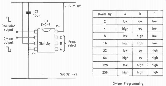
Fig. 6.5
For simplicity and ease of use it is hard to beat a ready-made crystal oscillator "module". These have been around for some time. Originally they were expensive, fairly large, produced only one frequency and were thirsty in terms of supply current.
Some still are, but there are now some that are not. The EXO 3 series of ICs are especially recommended to designers as an inexpensive source of accurate frequencies.
The EXO-3 IC contains a complete oscillator circuit, including the crystal, within a single 8-pin DIL package. Also within the IC is a programmable divider stage that can be set to divide the fundamental frequency by a powers of two from one to eight, so that nine different frequencies are obtainable from the single IC. Although not a "micropower" device, it uses CMOS technology so the supply current is small enough to allow use in battery-operated circuits. There are four versions of the device, differing only in primary oscillator crystal frequency, so for most applications there will be a frequency that is close enough to the one required. The cost of one of these chips is typically around $ 1.00, so they will often prove cost-effective in comparison with other design solutions.
The connections for the EXO-3 are shown in Figure 6.5. The supply is connected to pins 4 (negative) and 8 (positive) and should be between 3 and 6 volts, though the one tested by the author actually worked from less than 2 volts! Where available, a regulated 5 volt supply is ideal. A 100n ceramic or polyester decoupling capacitor should be connected across the supply as close to pins 4 and 8 as possible. The "standby" control input, pin 3, should be connected to positive to enable the oscillator to run. The three pins 5, 6, and 7 are used for programming the divider and can be connected directly to the positive and negative supplies to obtain the required division ratio, as shown in the table in figure 6.5. Two outputs are available. One is from pin 1, supplying the original oscillator frequency, internally buffered and boosted into a rail-to-tail squarewave. This output may not have a 50:50 duty cycle, although the one tested by the author, the 12MHz version, was very good in this respect. The next output, from pin 2, is also buffered and, since it is the product of at least one stage of division, it always has a precise 50:50 duty cycle. With light loads both these outputs swing practically from rail to rail. They can drive heavier loads than the Harris IC described earlier, a 1k load causes only a very slight loss of output amplitude.
The frequency is not trimmable, but being crystal-controlled is very accurate. A check on the output of the one tested showed a deviation from the set frequency of 0.000125%, which in a timing context is equal to just over 3 seconds a month. This is not to say that all EXO-3's will be this good, but it does suggest they are accurate enough for most purposes.
Whilst the maximum supply current is stated to be 20mA this varies with the crystal frequency, so this is the "worst case" for the highest frequency version which has an oscillator running at nearly 20MHz, and most examples probably won't draw anything like this. The 12MHz one tested drew just 2.6mA from a 5 volt supply and 1.1mA at 3 volts, making it very economical for such a high frequency.
The "standby" input connection, pin 3, is normally connected to positive supply to "enable" the oscillator action.
Connecting it to negative stops the oscillator and consequently reduces the device supply current to a few microamps. In this state both outputs go to the "low" or negative state, and can still sink current from loads connected to them. The "start-up" time when pin 3 goes high is stated to be a maximum of 1.5ms, which is rapid for a crystal oscillator, so in many applications gating the signal with this input will be a useful option.
The four primary oscillator frequencies available are 12MHz, 14.31818MHz, 16MHz, and 19.6608MHz. Readers can check the outputs available from the dividers of these for themselves, using a calculator to divide by two up to eight times. However, it will be seen that the 16MHz version will give a precise 1MHz output when the divider is set to divide by 16. There is no reason why extra stages of division cannot be added using any of the CMOS dividers, and when checked with a calculator it will be found that a few extra stages applied to the 19.6608MHz device will produce all the commonly used data baud rate frequencies between 75Hz and 19.2kHz. A couple of 4024B 7-stage dividers could generate them all simultaneously.
The EXO-3 device was chosen for this section because it is very inexpensive and simple to use, although other fully integrated crystal oscillator ICs are available. Two that might be of interest are the PXO 600 and PXO 1000, both supplied in 16-pin DIL form. These are similar to the EXO-3 but have six divider programming pins and are each capable of generating fifty-seven different output frequencies. The PXO 600 spans a range from one cycle every 200 seconds to 600kHz, and the PXO 1000 covers approximately two minutes per cycle to 1MHz. These ICs are also visually interesting since they have quartz windows through which their crystals can be seen! Unfortunately they are slightly more expensive at around $25.00, though this is still relatively cheap for such a device. A data sheet covering both versions is available to designers wishing to use one of them.
Also see: