.Keep ‘em playing! That was the motto of radio fans back in World War II, when the diversion of industrial production from consumer goods to defense needs made new radios as scarce as hens’ teeth. Those days were a real test of a radio repairman’s ingenuity. To keep the old sets playing, we dreamed up many improvisations and expedients. What follows is a few ideas that will help the radio restorer of today to keep the sets of yesterday playing. These are just a few of the many ideas that can be used, but they should solve lots of problems and stimulate you to come up with some ideas of your own.
It is always best to replace defective parts in any radio set with identical parts. However, it is not always possible to do this. To handle such a situation, a good repairman makes emergency repairs or finds some way to make a substitution. These emergency repairs are not infallible. In circuits in which electrical characteristics are critical, these repairs may not work. For the most part, however, they will work under the conditions indicated.
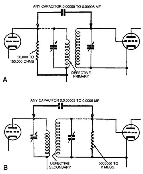
Burned-out primaries and open secondaries of transformers can be repaired by using an RF choke or a resistor in place of the open winding and by connecting a coupling capacitor from primary to secondary. (See FIG. 1) A resistor for the primary may be from 50,000 to 150,000 ohms; for the secondary, from 0.5 to 2 megohms. The capacitor may be from 0.000025 F to 0.0005 F for radio frequency and from 0.01 to 0.1 F for audio frequency. (See FIG. 1). When one-half of a center-tapped secondary of an audio transformer burns out, substitution can be made as illustrated in FIG. 2.

FIG. 1. Method of substituting a resistor and capacitor for open winding.
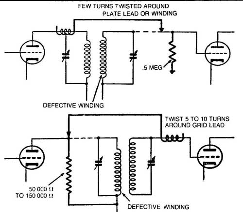
Where a capacitor is not obtainable, a few turns of wire wound around the good winding or high RF lead and then connected to grid or plate, depending on which winding is open ( FIG. 3), may give the desired coupling.
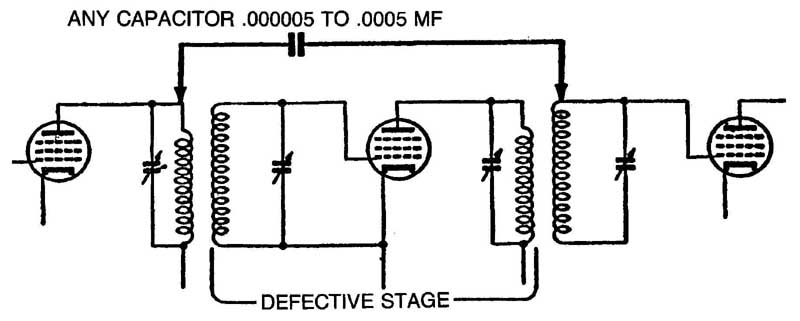
When a defect has been isolated to a particular stage in the set and a repair or replacement is not possible, the stage may be bridged by connecting a capacitor from the plate of the stage preceding the defective stage to the grid of the stage following the defective stage, as shown in FIG. 4. This will not work for detector stages. Use a 0.0005uF capacitor for RF and IF stages; use a 0.01-uF capacitor for AF stages.

FIG. 2. Substitution of resistors for transformer winding.

FIG. 3. Method of substituting a resistor and a few turns of wire for open
winding.

FIG. 4. Method of bridging defective stage.

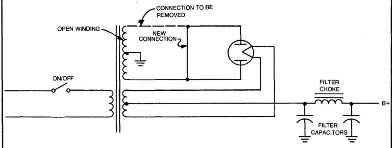
FIG. 5. Using a power transformer that has half of its high-voltage winding
open.
CAPACITOR AS TEST INSTRUMENT
An ordinary bypass capacitor can be used to localize noise or oscillation (squeals). By connecting the capacitor between the grid and ground at the input of each stage, starting at the final stage, the trouble can be localized to the stage where the noise or oscillation is not affected by the capacitor. Shunting cathode, screen and plate bypass capacitors with a capacitor known to be good often shows open or partially open capacitors much quicker than disconnecting and testing each capacitor separately.
USING A POWER TRANSFORMER WITH HALF OF THE HIGH-VOLTAGE WINDING OPEN
Sometimes it is possible to still use a power transformer even though there is an open in one-half of the secondary winding, lithe transformer is in a full-wave rectifier circuit, the circuit can be converted to a half-wave circuit as shown in FIG. 5, thus bypassing the defective part of the winding. To do this, just remove the connection shown as a dashed line in FIG. 5 and add the new connection shown. This is a very easy change to make—much easier than installing a new transformer, even if you’re lucky enough to find one.