There are many techniques you can use to troubleshoot problems with televisions. Most of these techniques require specialized electronic equipment. This Section describes the basic techniques you can use to test the electronic components that make up a television. Later Sections will describe specific techniques for specific problems.
Basic Equipment for Troubleshooting Televisions
Examples of the basic pieces of equipment that help in troubleshooting problems with televisions include:
1. Oscilloscope.
2. Digital multimeter (DMM) or a volt-ohmmeter (VOM).
3. CRT tester.
4. CRT test jig.
5. Color bar generator (NTSC).
6. Degaussing coil.
7. High-voltage probe.
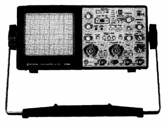
FIG. 1. An oscilloscope.
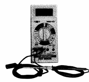
FIG. 2. A digital multimeter (DMM).
An oscilloscope, shown in FIG. 1, is like a voltmeter that measures changes to AC waveforms and DC voltages and displays the changes on a screen. However, unlike a voltmeter, the oscilloscope can measure and display very rapid changes to voltages like those found in televisions. Also, the waveforms are traced to the oscilloscope’s screen, letting you see the shape and size of the waveform.
A digital multimeter (0MM), shown in FIG. 2, and a volt-ohmmeter (VOM), can be useful tools for measuring current, voltage and resistance. They also can be used to check capacitors, diodes, and transistors. DMMs can make finer measurements than volt-ohmmeters, and multimeters can be analog or digital. When choosing a 0MM, make sure the DMM can read the switching circuits (low ohms function).
A CRT tester, like the one shown in FIG. 3, can be used to test a picture tube that is not working correctly. A CRT tester is portable and can be used to test a CR1 in someone’s home, if necessary. However, the CRT test jig shown in FIG. 3 is a better diagnostic tool on the bench because it can replace the picture tube and be used to quickly determine if a picture problem is in the CRT or the receiver.
A color bar generator, shown in FIG. 4, can produce color bar, dot and crosshatched patterns that help when working with color setup procedures because the signal source has known properties. The color bar generator must meet NTSC standards.
 FIG. 3. A CRT test jig.
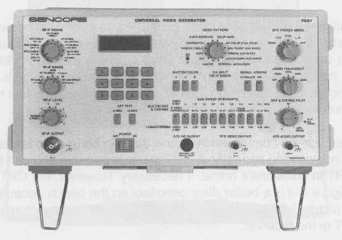
FIG. 4. A color bar generator
The manual degaussing coil, shown in FIG. 5, demagnetizes the CRT and improves the picture’s quality. When color CRTs become magnetized, picture quality is greatly reduced.
A high-voltage probe, like the one in FIG. 6, is used to detect the high voltage used by the television. It can be used as a diagnostic tool to make sure the CRT has the correct high voltage when there is no picture present or when the picture quality is poor or varies. It also can be used to detect excessively high voltage which causes X-ray radiation.
General Techniques for Servicing Televisions
Before you start, make sure you have the proper equipment, and that the equipment is properly calibrated and in good working order. Also, make sure you have the proper documentation and schematics for the brand of television you are repairing. Then, follow these general guidelines for locating the source of the problem.
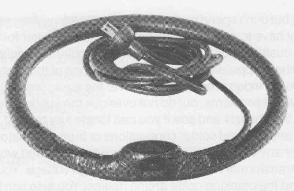
FIG. 5. A manual degaussing coil.
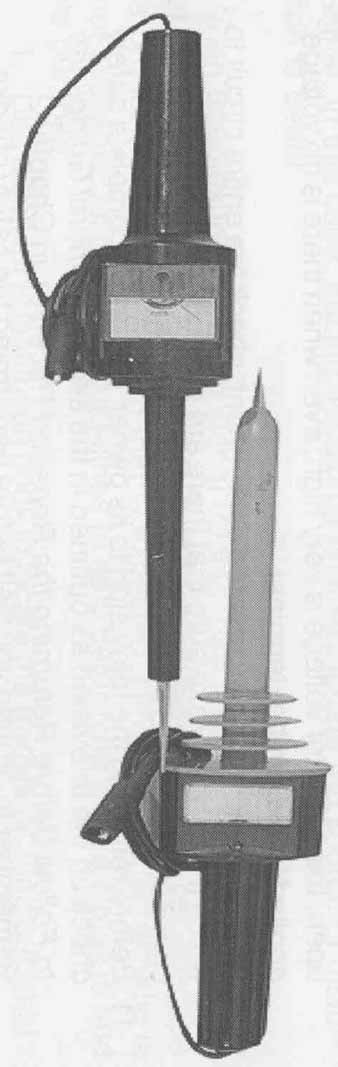
FIG. 6. A high-voltage probe.
Take your time, but don’t spend hours tracking a problem with no results. Some times you might have to contact the television’s manufacturer for help:
1. Ask the customer for a description of the problem. It might be helpful to ask what happened prior to the appearance of the problem.
2. Observe the video product and listen to the audio product. Look for the apparent problems, but do not overlook the subtle distortions.
Look at the chassis and see if you can locate any burned areas. Also, look for any cracked solder connections or burned resistors.
3. Listen for any unusual sounds, such as a ticking sound when the flyback transformer receives excessively high voltage. You can hear static and the cracking noise arcing makes. You also can hear the hums that components can make when they are not working properly.
4. Notice any unusual smells that the television produces. For example, is there an odor of overheated components or ozone which is typically from a burned resistor or excessive high voltage? Also, feel the outside of the television to see if there are any excessively hot areas. The vertical and horizontal stages, and the power supply can produce excessive heat.
5. Check the fuses. Perform a visual check and measure the resistance of the fuse.
6. Look at the schematics for the specific model and brand of television to see if you can locate any obvious problem source.
7. Test the controls and observe the effects of the adjustments. While doing so, use the schematic to see if you can isolate the circuit that could be the source of the problem.
8. When you isolate the circuit(s), determine their inputs and outputs. Also, locate the power source for each of the suspected problem circuits. Check the circuits that precede and follow the suspected circuit(s). Again, the schematic is very helpful in this step.
9. Use the oscilloscope to make sure the input and output signals are the appropriate strength for the suspected circuit(s) and its supporting circuits or components. A loss of signal can be caused by an open series transistor or a shorted parallel component. When a transistor is open, the collector voltage is very high, even when there is no voltage applied to the emitter terminal.
10. Before replacing the suspected component, check the entire circuit to which it belongs. Make sure that there are no faulty components or connections around the component you are replacing.
11. Before returning the television to its owner, perform a complete safety check on the television as outlined in the section General Guidelines to Follow Before Returning the Repaired Receiver, in Section 2. Remember to ground yourself before performing the safety checks, especially if checking the ICs or any solid-state circuits.
Troubleshooting Methods
The main electronic troubleshooting methods are:
1. Using signal injection and signal tracing.
2. Analyzing circuit voltage.
3. Measuring resistance.
4. Substituting parts.
Signal Injection and Signal Tracing
Signal injection is inputting a signal that is produced outside of the television into the circuit that you have identified as the possible source of the problem. Normally, you would start injecting the signal at a component’s output point.
For example, if you inject a video signal into the output of the first video amplifier and the CRT produces a picture, the circuits are working properly between point where the signal was injected and the CRT. Then, you would move to the input of the first video amplifier. Inject a signal into the input. If the CRT does not produce a picture, then the video amplifier is the source of the problem.
Signal tracing is the opposite of signal injection. Signal tracing tracks a signal through a circuit to make sure the signal goes from the input point to the output point properly. For example, using an oscilloscope, check the waveform of the input signal to the video amplifier. If the input is correct, check the signal output from the video amplifier. If the signal is not correct, the video amplifier is the source of the problem.
Although signal tracing can be used, signal injection is most used for low- level, high-frequency circuits in tuners and IF circuits. Likewise, signal injection is less effective than signal tracing when testing the audio amplifier. This is because when you are tracking the source of audio distortion, injected signals many times do not sound as distorted as the transmitted signal. In this case, tracing the signal until you locate the source of distortion is better.
When troubleshooting using signal tracing, use a schematic with a picture of the correct waveform in order to compare the waveform the oscilloscope is producing to the waveform that is expected. However, if a schematic is not available, follow these guidelines to help determine what a circuit is and its purpose:
1. Use a data or substitution book to locate the transistor. Find out what the transistor is made of—silicon, germanium, NPN (Negative-Positive-Negative) or PNP (Positive-Negative-Positive). Also, find out what the transistor is used for and about its basing. The basing is important because a replacement transistor does not always have the same basing as the component it is replacing. If there is no basing available, you must perform the following test to determine the correct element to use. FIG. 7will help familiarize you with the structure of a transistor.
2. Use an ohmmeter to see if any element, such as the base, collector or emitter on a transistor, is grounded.
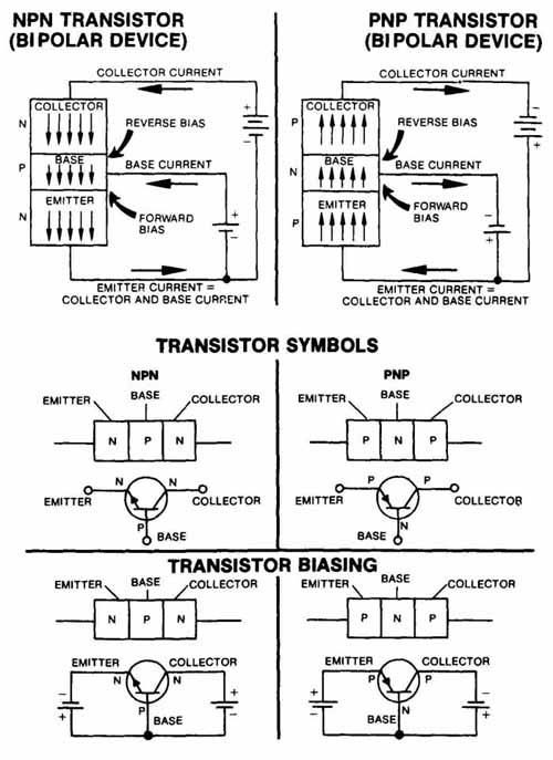
FIG. 7. Diagrams showing the structure of two transistors, NPN and PNP
3. Try to determine the base by following the signal of the preceding stage. If the transistor is being used as an amplifier, the output at the collectors will be of higher amplitude, and inverted. If the transistor is being used as an emitter-follower (common collector), the output signal on the emitter will be approximately the same as the base signal, and not inverted. On many receivers, the video stage is made up of common collector amplifiers—the output signal from the emitter is the same amplitude and the same polarity as the input signal.
4. Using signal tracing, identify which is the output lead by determining which of the transistor’s leads is coupled to the next stage in the process. Stages are connected by capacitors, resistors, and coils or transformers. Also, stages are many times arranged from left to right on the chassis. This means that the initial input is on the left side on the chassis. Then, the next stage follows to the right, and so on. Schematics follow the left to right pattern of transistors on the chassis.
5. Normally, by measuring voltages from ground, the base and emitter are easy to locate. If you know the type of transistor, such as a NPN, the most negative voltage is the emitter. The collector is reverse biased or positive. The base and the emitter have a voltage difference of 0.03V for germanium or 0.07v for silicon. However, this method of identifying what the transistor is made of is effective only if the amplifier is working almost normally and is used as a class A amplifier. Class A amplifiers run all of the time. Class B amplifiers turn off after a time. Class C amplifiers act as a switch for other amplifiers. If the circuit is operating as a switch (class C), these values are not reliable.
When troubleshooting, paying close attention to details is very important. For e if the output signal at the collector is the same amplitude and polarity as the base, and the circuit is a common emitter circuit, the problem could be a shorted transistor which allows the base signal to be applied directly to the collector lead. A circuit that is operating correctly will have output at the emitter, and the output will be the same amplitude and polarity as the input.
When you locate the defective stage, test the transistors in that stage first. Component failures usually happen in the following order; therefore, it might save time to check the components in this order:
1. Active components (such as power transistors, large current resistors or small electrolytic capacitors) amplify, switch or control a function. High voltages and excessive heat can cause the active power components to fail. Check transistors first because they produce heat, and are susceptible to power surges and spikes.
2. Passive components are resistors, low-wattage resistors, coils and low-voltage capacitors. Check the resistors first because they produce heat and can deteriorate overtime. Then, check the capacitors because they can be damaged by the heat around them and by power surges. Also, a capacitor’s insulation can deteriorate.
Analyzing Circuit Voltages
Measuring the voltage around an integrated circuit or transistor can many times help you locate a defective component. For example, you can use a DMM with the diode test function to measure the voltage at a transistor. Also, high voltage to the collector might indicate an open transistor or one that is biased to cutoff.
To see whether the transistor is open or biased to cutoff, connect a voltmeter across the transistor from the emitter to the collector. Then, connect a 100K resistor from the collector to the base.
The base must be positive for the transistor to conduct. If the transistor biases on, the voltmeter shows a decrease in the voltage drop across the transistor. This indicates that the transistor is good and can control the current passing through it. Do not short the base collector junction. This can damage the transistor.
If the emitter’s voltage measurement is too high, voltage drop across the emitter resistor will be too high. This can indicate that too much current is passing through the resistor or that the resistance has increased. If too much current is passing through the resistor, it is conducting too heavily or there is an open bypass capacitor. Therefore, if the capacitor opens, the signal can degenerate and cause a large voltage drop across the resistor. Check the base voltage to see if it is causing the transistor to conduct too heavily. The result can be an increase in forward bias—positive for an NPN transistor and negative for a PNP transistor.
If the emitter’s voltage is too low, the transistor might not be conducting correctly or may be turned off because, if the voltage is too low or the polarity is incorrect, the transistor will not conduct. Also, if the emitter’s voltage is too low, the bypass capacitor might be shorted or leaky—letting current flow where it is not supposed to. It also might mean that the emitter’s resistor might be faulty. If the capacitor is not shorted or leaky, and the resistor is not faulty, the transistor is probably damaged.
Measuring Resistance
Sometimes it can be useful to use Ohm’s law to troubleshoot a resistor or a resistor array. Measure the resistance in parallel or series, use Ohm’s law to check if you have the correct value. Ohm’s law states that for any circuit, the electrical current is directly proportional to the voltage and inversely proportional to the resistance.
Before you measure a circuit’s resistance, unplug the television. Then, when you measure a circuit’s resistance, think about the following:
1. Check the schematic before measuring a circuit’s resistance to make sure there are no parallel paths that you could measure simultaneously. Parallel paths decrease the total resistance. Just to make sure you are not picking up stray resistance from other components, gently lift one side of the component, especially diodes. This breaks the circuit and ensures that no stray resistance is being measured. Then, test the component.
2. When measuring a circuit’s resistance, having a nonparallel path can cause a component to measure a greater value than its rated value. Therefore, if the ohmmeter’s leads are placed directly on each end of the component, there is no way that the component can measure greater resistance than its rated value unless the component has increased in resistance.
3. If a component measures less resistance than its rated value when checked in the circuit but normal when measured out of the circuit, a parallel path is being measured. This parallel path could be a junction of a transistor or a diode, or it could be that a capacitor is conducting when capacitors usually do not conduct. This is one way to identify a leaky capacitor. If you are testing connections for transistors or diodes with a low-power ohm range, you might have to remove the component before testing it or use a test voltage that will not cause the connection to conduct.
Substituting Parts
Sometimes part substitution will help in locating the source of the problem. For example, if the picture is collapsing vertically, usually a capacitor is faulty. Take a capacitor of like or greater value and type, and bridge across the suspected faulty capacitor. If picture quality is restored, replace the faulty capacitor.
Testing for an open base to the collector. --Testing for a short to the collector emitter.
Testing for a leak between the base and emitter
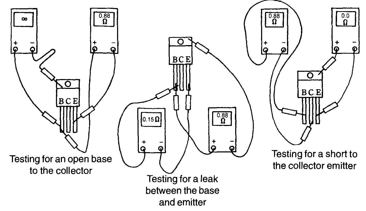
FIG. 8. Using a digital multimeter to check for shorted, open, or leaky transistors.
Testing Components
The following sections describe the basics of locating defective or faulty components. These topics are described in more detail later in the guide.
Locating Defective Transistors
When a transistor is open, it means that a connection is not complete and current is not flowing. A cold soldered joint is an example of an open connection. When you measure leads on the transistor, if any of the leads measure low resistance (0-10 ohms), the lead may be shorted. Be careful. Some transistors might have low resistance diodes and resistors built in. Refer to the schematic from DATASHEET for the components and the expected values.
This section discusses testing how well the transistor can control current. To do this, use a transistor tester, or a digital multimeter like the one shown in FIG. 8.
Only use an ohmmeter or a multitester to test for a leaky or open transistor, such as we did in the previous test for locating defective transistors. As they age, transistors can begin to leak current at the emitter-collector junction.
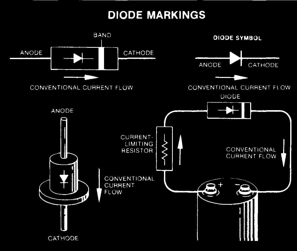
FIG. 9. A diagram depicting diodes and their markings.
Locating Defective Diodes
A diode, shown in FIG. 9, is a device that lets current flow only in one direction. Notice the special markings on the diodes in the figure. The arrows show the conventional current flow. Diodes have polarity; therefore, they must be placed in circuits in the correct direction. Small diodes are used for low- current applications in circuits up to 1 amp of average current and are marked with a band to indicate the cathode end. Large diodes are rated in terms of their peak and average forward current-carrying capabilities and are marked with the diode symbol to indicate their polarity. Do not exceed the rated value of a diode. A transistor is really two diodes, back-to-back.
You can use a multimeter to check whether a diode is open or is leaking current, as we did in the previous section, Measuring Resistance.
Locating Defective SCRs
A silicon controlled rectifier (SCR) is basically used as a switch, as shown in FIG. 10. Use a DMM to check the voltage on a SCR.
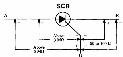
FIG. 10. Diagram showing the switching action of a silicon-controlled rectifier,
or SCR.
Locating Defective ICs
Use a DMM to locate a defective IC. If a component is leaking current, the voltage on the terminals will be low, especially the terminal directly supplied by the low voltage power supply. If you measure a low resistance between the terminal pin and the chassis ground, and there is no external path to ground, you may have a defective IC.
An open connection in the IC can produce an intermittent problem, and intermittent problems are difficult at times to trace. You can apply a cold spray to the IC and then lightly tap it. This sometimes reveals a broken solder joint. however, if you apply a signal to the input and get no output from the IC, and all external components are good, replace the IC.
Surface-Mount Technology (SMT)
Surface-mount technology (SMT) has dramatically changed the television chassis. FIG. 11 shows a comparison between SMT and IMCs (insertion mount components) used in earlier television models. SMT offers smaller and lighter components whose leads are part of the board and that can be soldered directly to the television’s wiring. Smaller components are usually located on the bottom of the board and the larger components are usually located on the top of the board. Using double-sided boards, television manufacturers can produce a smaller, lighter, and more compact chassis.
The mounting methods of SMT and IMC components are different. Every solder connection is a possible failure point. Solder connections can weaken or, as with a cold solder joint, not conduct at all. Therefore, when SMT manufacturers reduce the number of solder connections, they reduce the number of potential problems in televisions.
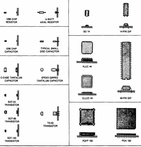
FIG. 11. A chart comparing SMT and 1MG components.
SMT boards have smaller leads than IMCs. In fact, chip passives (capacitance and resistance arrays) do not have leads. This makes the paths between components shorter, which boosts the performance. Each additional millimeter of lead adds inductance, capacitance and resistance, called parasitics, to the signal path. Reducing the distance between components can improve circuit performance. Also, a component’s lead can act as an antenna, receiving radio-frequency signals. By reducing the length of leads, the SMT is provided with some external noise protection.
Some companies are producing “universal replacement” components for SMT boards. However, use care when replacing components; it is best to use an exact factory replacement from the television’s manufacturer. The “universal” replacement parts and the exact replacement parts might look the same, but sometimes they are not.
When you remove a surface-mounted component, keep in mind the following suggestions. Always use a soldering iron and a desoldering iron especially designed for SMTs. Never use a soldering gun:
1. Carefully remove the defective component by lightly touching a soldering iron to melt the solder at one end or at each terminal on one side of the component.
2. Using tweezers, gently lift the end from which you removed the solder as you lightly touch the connection on the other end or side of the component with the soldering iron.
3. As the solder melts away from the joint(s), gently lift up and twist the component until it is free.
4. Using the desoldering iron designed for SMTs, remove any solder fragments, and any glue if the component also was glued to the board.
Make sure the surface and all leads are clean.
When you replace the component, follow these steps:
1. Preheat the component, except semiconductors and IC processors, using a small, hand-held heater or even a hair dryer. Never preheat a semiconductor or an IC because excess heat can destroy them.
2. Place solder at the contact points.
3. Press the component into the solder, gently but firmly. Be careful when you solder the joints. Excessive heat or heat applied for too long— longer than 3-5 seconds—can destroy the component or lead.
4. Apply the solder directly without rubbing the joint as you apply the solder. Also, be careful not to break the component by applying excessive pressure. These parts are very small and somewhat delicate.
Servicing Solid-State Devices
When you are servicing solid-state components, you can easily destroy them by applying too much voltage or voltage surges, ignoring the polarity, using excessive heat, or exposing them to high-energy magnetic fields. Therefore, test the voltage in a circuit before you replace a transistor or IC. Also, remember to use exact replacements. As mentioned above, “universal” replacements might not be exactly the same as the television manufacturer’s replacement. This can cause problems with the operation of the television or possibly dam age it. Also, pay close attention to the schematic for the brand and model of television and to the manufacturer’s recommendations when replacing parts.
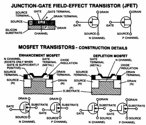
FIG. 12. MOS and FET devices.
When soldering solid-state devices, use a heat sink to draw the soldering iron’s heat away from the device.
For MOS (metal oxide semiconductor) devices, ground yourself and the soldering iron to prevent static electricity charges from forming. As with SMTs, use a soldering pencil because a soldering gun has a magnetic field around it that can damage MOS or FET (field effect transistor) devices. FIG. 12 shows a diagram of an MOS and an FET.
Also, when you cut the leads of MOS and FET devices, use a sharp, scissors-like cutter such as a wire cutter ( FIG. 13), and not a pincher cutter. The wire cutters make a clear cut with out sending shock waves through the device.
Protect the components from high-voltage arcing because it can destroy solid-state devices. Therefore, do not bridge filter capacitors across a faulty capacitor while the television is receiving power. Make sure that the television is well grounded and that all connections are grounded. If you have to remove a ground or place a jumper between two points, turn off and unplug the television first. Also, make sure that jumper wires and probe wires are in good condition. Bare wires and exposed meter terminals can damage a solid-state component, as well as deliver a shock.
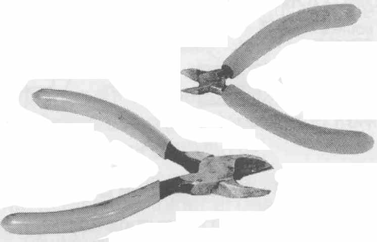
FIG. 13. Two types of wire cutters.
When you are using probes to test components, make sure the points of the probes are sharp. The points may have to penetrate oxidation that has formed on the joint. Also, sharp probe points keep the points from slipping as you are using them. Do not touch the leads directly; instead, touch the leads. When you touch the leads directly, the probe points, though sharp, can slip between the leads and cause a voltage arc.
Digital Circuits
It is important to understand digital circuits and learn how to troubleshoot these circuits. The basics of and theory behind digital circuitry is described in basic electronics books. There are advanced books that describe more advanced concepts of digital circuitry and how to troubleshoot a digital circuit. This guide will not cover troubleshooting digital circuits.
Helpful Diagrams
The following diagrams depict information commonly available in DATASHEET, and will be useful tools for you.
The parts list gives manufacturer part numbers and describes the components you will be working with. ( FIG. 14.)
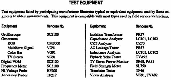
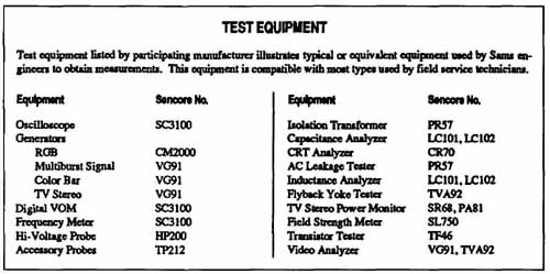
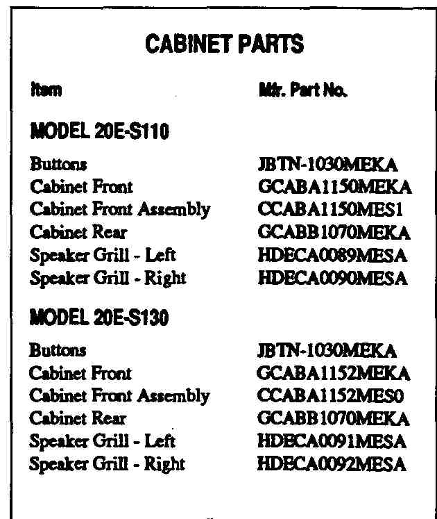
FIG. 14. Television parts lists.
Placement Chart
The placement chart shows the top and bottom (when appropriate) of a circuit board, and shows the exact placement of the major component. ( FIG. 15.) In some cases, placement charts or photographs also provide a grid map that has the component callout and the grid location to help you locate a component.
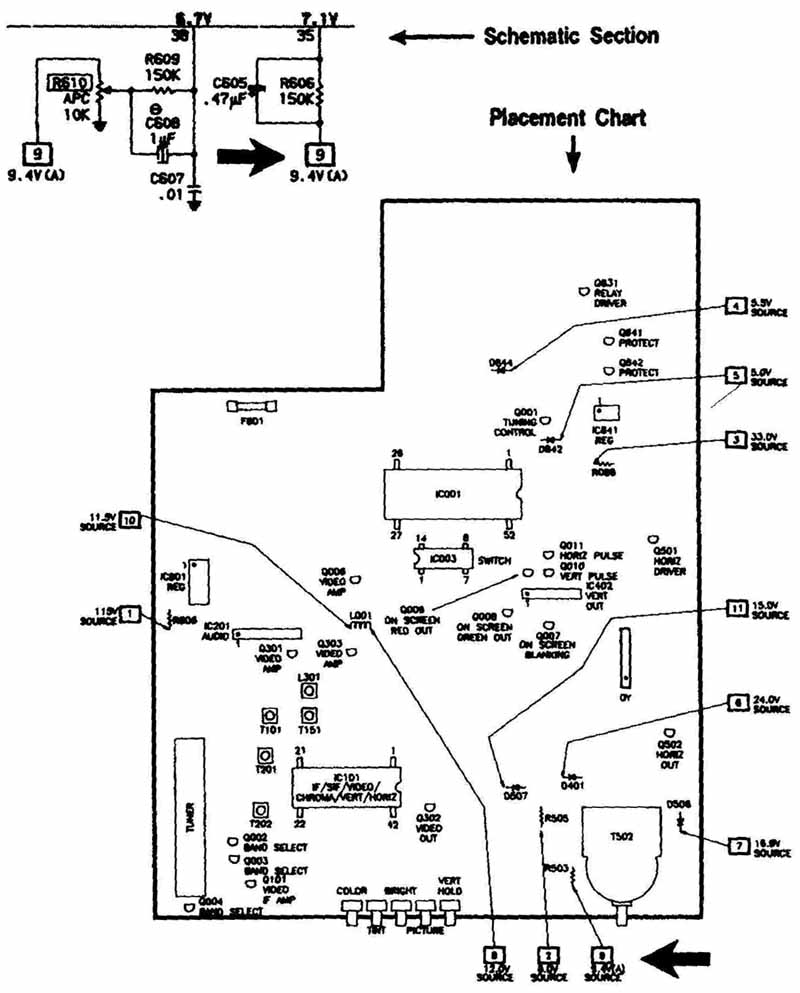
FIG. 15. A. placement chart.
Schematic
FIG. 16 shows a portion of the type of schematic that you will use when troubleshoot and repairing televisions. The schematic IS broken into stages, showing the components in each stage. If you need to jump to another schematic, the page and stage number of the new location are also included.
Quiz
1. In the audio circuits, which troubleshooting method is best: signal injection or signal tracing?
2. What does SMT stand for?
3. Why use sharp probe points?
4. Why do you NOT use a soldering gun when working with MOS and FET devices?
5. What is a cold solder joint?
Key
1. Signal tracing.
2. Surface mount technology.
3. To reduce the chances of slipping off of the leads of components, and thereby prevent shorting or arcing.
4. The magnetic field generated by soldering can damage some MOS and FET devices.
5. An open connection on a PC board.