A power supply is the circuit that supplies the energy to operate a television. It can be a separate assembly, or it can be integrated into the electrical system of the television. In today’s televisions, the power supply components are usually complex. This Section discusses the various power sup plies in televisions and outlines some troubleshooting techniques you can use to locate a problem with the television’s power supply. A block diagram of basic power supply stages is shown in FIG. 1.
Also, some chassis require you to use an isolation transformer, shown in FIG. 2, when you troubleshoot power supply problems.
Standby Power Supplies
Standby power supplies are located on the hot ground side of the power supply and secondary connections are usually cold ground. This power supply offers a means of turning the television on and off and using a remote control. These circuits are always on.
If you suspect that a standby power supply is faulty, use a voltmeter to test each component in the circuit. Then, place a jumper across the mode switch’s emitter and collector terminals to see if the chassis turns on. Then, test each transistor and diode in circuit. If you find a leaky or open component, replace it.
Conventional Power Supplies
Most television circuits require a power supply that provides DC voltage. The basic unregulated DC power supply functions are transformation, rectification, and filtering. These functions are illustrated in FIG. 3.
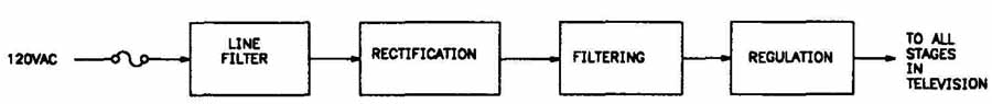
FIG. 1. Basic power supply stages.
The transformation function input from the utility line is the 110V AC. Its AC output voltage, which can be lower or higher than the input voltage, is the input to the rectification function. The rectification function output is a DC voltage, but because it has large amplitude variations, it is called a pulsating DC. The filtering function reduces the large amplitude variations of the output to a DC voltage with only a small “ripple” voltage riding on it. This basic power supply is called an unregulated DC power supply because its output varies with the changes in the AC input voltage, as well as changes in the load on the power supply output. To help you understand the operation of this power supply, each of the functions is discussed below.
Transformer
A transformer is the component that performs the following two functions:
1. Transforms the AC line voltage value required to produce the proper AC voltage input to the rectification functions.
2. Electrically isolates the electronic equipment from the utility power lines.
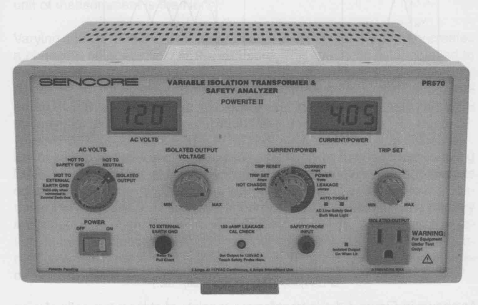
FIG. 2. An isolation transformer.
As shown in FIG. 4, the transformer consists of at least two coils of wire wound on the same iron core. The coil of wire receiving the input voltage is called the primary. The coil of wire receiving the output voltage is called the secondary. Many times there are two or more places in the secondary from which the outputs are taken.
The basic operating principle of a transformer is induction—the capability of a coil to store energy in a magnetic field surrounding the coil. As the current increases, the magnetic field increases. As the current decreases, the magnetic field decreases. The expanding and collapsing magnetic field induces a counter voltage in the coil that opposes the varying current that produces the original field. This opposition to AC is called inductive reactance, and its unit of measurement is the Henry.
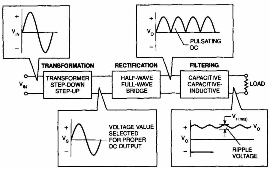
FIG. 3. Transformation, rectification, and filtering of an unregulated DC
power supply.
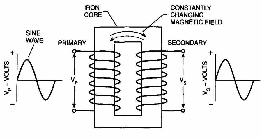
FIG. 4. Transformer construction.
Varying current from an AC voltage when it is applied to the primary creates a changing magnetic field in the iron core. This magnetic field, coupled to the secondary through the core, cuts into the secondary windings and induces an AC voltage in each turn of the secondary. Thus, energy is transferred from the primary to the secondary by varying the magnetic field with out any electrical connection between them.
Because the energy transfer is accomplished only by the magnetic coupling between the primary and the secondary, the secondary and any circuits connected to it are isolated from the primary and any other circuits connected to the primary. This is very important for safety because the primary is connected to the high current supply of the utility line. Without such isolation, there is a serious shock hazard. Another advantage is that no DC connection exists between the circuit ground in the primary circuit, and the circuit ground in the secondary circuit.
In an unregulated power supply, the transformation function must provide an AC output voltage value required to produce the proper DC output voltage. This is easily accomplished in a transformer by varying the ratio of the number of secondary turns to the number of primary turns. The secondary voltage can be made less than or greater than the primary voltage simply by varying the turns ratio.
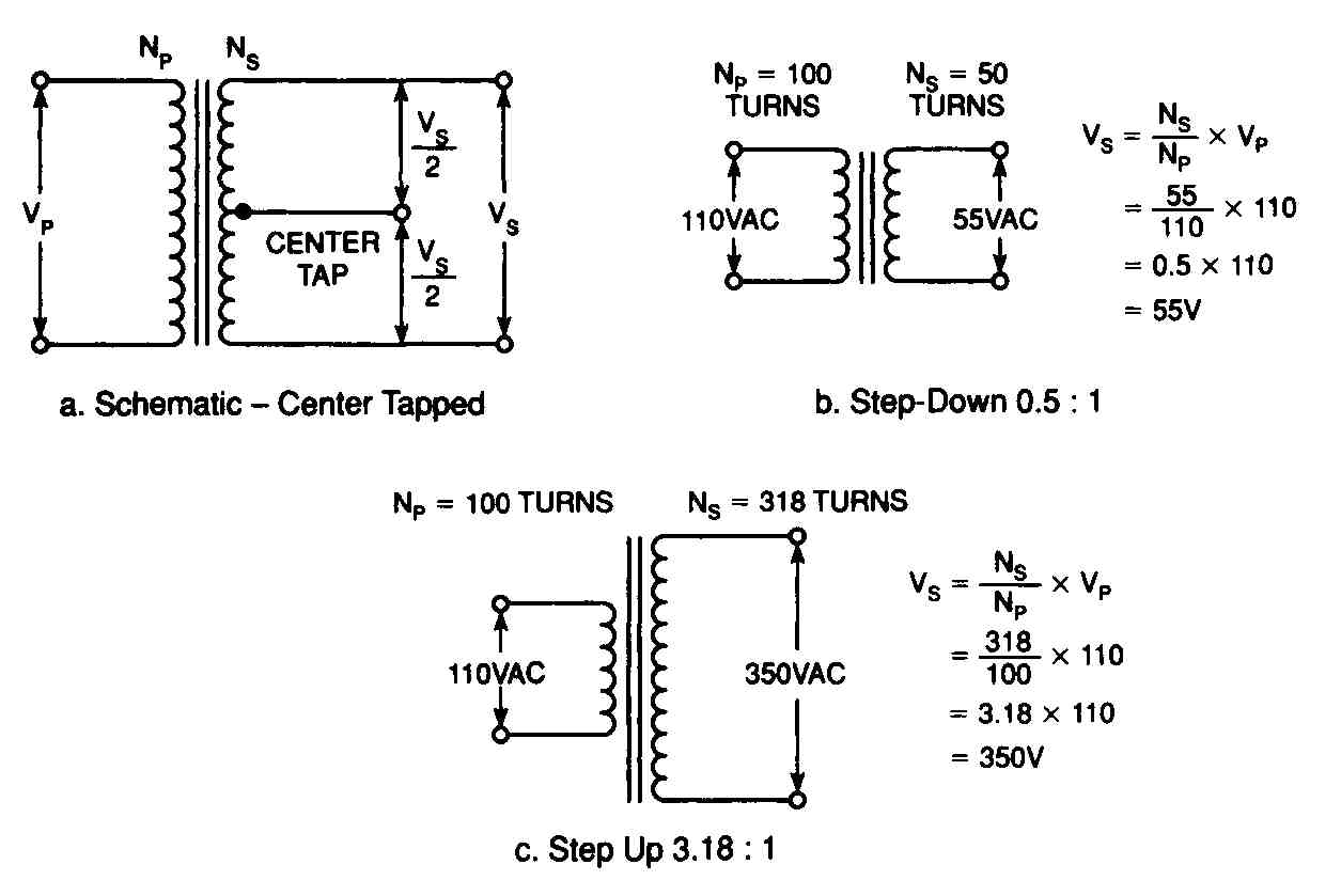
FIG. 5. Diagrams of various types of transformers.
Knowing that the secondary voltage is the primary voltage times the turns ratio, it is easy to see how the transformer can be used to vary the voltage level of the AC voltage used in the unregulated power supply system.
FIG. 5 shows several examples using schematic drawings for several types of transformers:
1. In the step-down transformer there are fewer secondary turns than primary turns, and the secondary voltage is less than the primary voltage. However, the current is stepped up.
2. In the step-up transformer there are more secondary turns than primary turns, and the secondary voltage is greater than the primary voltage. However, the current is stepped down.
Rectification converts an AC voltage into a DC voltage. A diode performs the rectification.
The rectifier acts as a one-way valve for electricity, as shown in FIG. 6, because the diode lets electrons flow freely in only one direction. Forward- biased means that the anode voltage is more positive than the cathode voltage. Reverse-biased direction is the opposite of forward-biased, and the anode voltage is more negative than the cathode voltage. In reverse-bias, the electrons cannot flow as easily as in forward-bias.
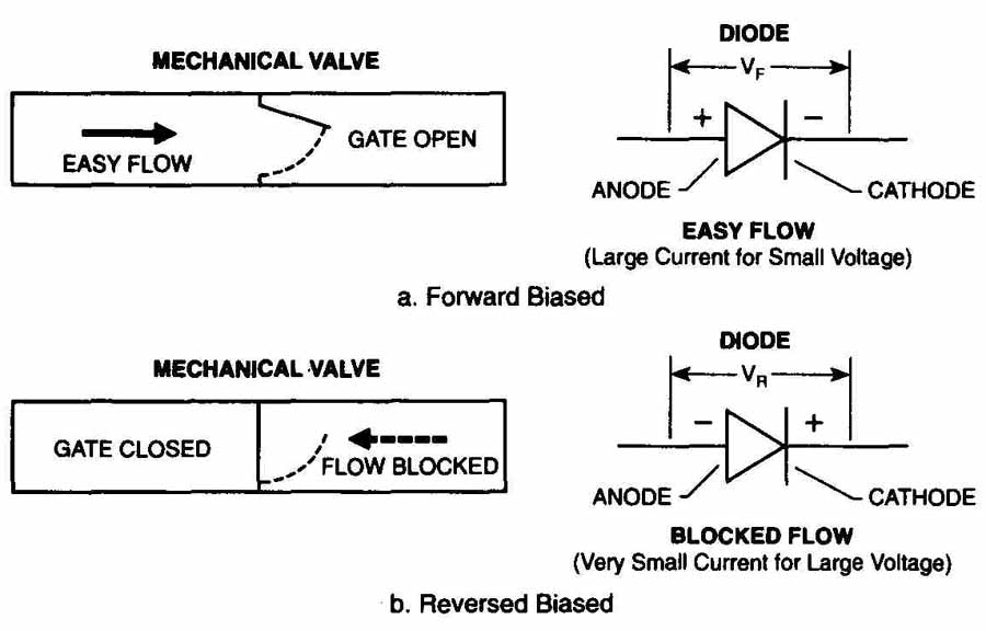
FIG. 6. Forward-biased and reverse-biased rectifier.
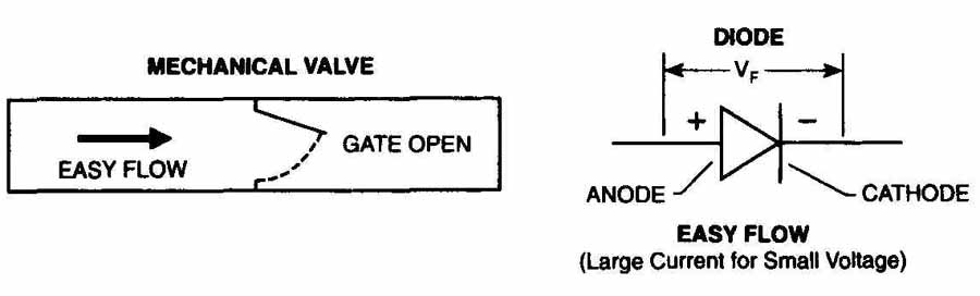
FIG. 7. A forward-biased diode.
Forward-Biased Diode (VF)
A forward-biased diode is like an electronic valve that’s open: it allows the current to flow in only one direction. The resistance of a forward-biased diode is enough to develop a voltage drop across it. The most common diode is made of silicon and has a typical voltage drop of .5V to .7V. A germanium diode has a typical voltage drop of .05V to .2V. The silicon diode in FIG. 7 requires the anode to be .7V more positive than the cathode, to be forward-biased, and to allow current flow. If the forward- biased current exceeds the rated value in amps, it could result in permanent damage to the diode.
Reverse-Biased Diode (VR)
The maximum reverse-biased voltage that can be applied to a diode, shown in FIG. 8, is called the peak inverse voltage (Ply). If this voltage is exceeded, the anode-cathode junction may break down and let a large current flow in the reverse direction, plus the diode will probably be permanently damaged.
Half-Wave Rectifier
The half-wave rectifier circuit is really one diode with an output of 60 Hz, and is used for low-current applications. A simple half-wave rectifier circuit has a diode connected in series with a transformer secondary output, as shown in FIG. 9. The input primary voltage is a power line, 60 Hz, sine-wave voltage. The positive cycle alternation is labeled A. The negative cycle alter nation is labeled B. The polarities of the primary and secondary voltages are noted for each alternation.
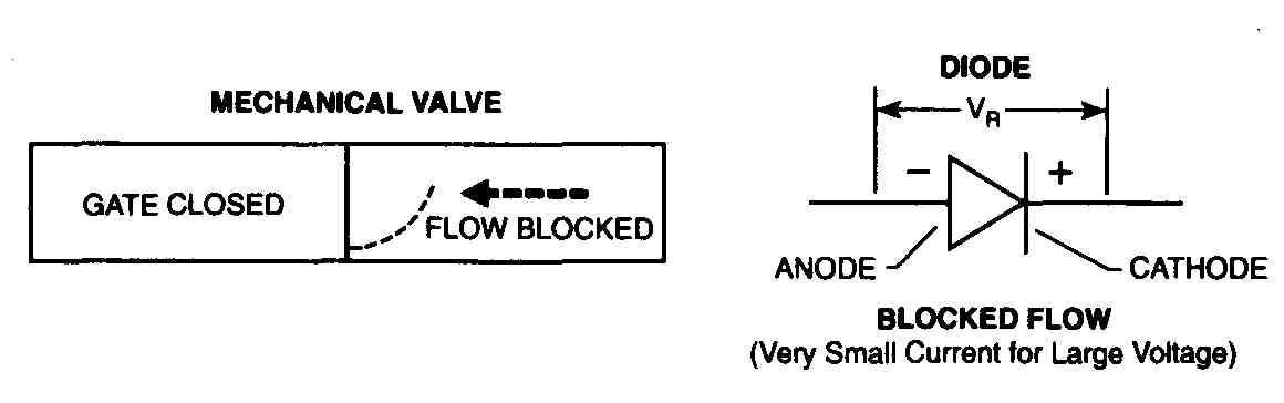
FIG. 8. A reverse-biased diode.
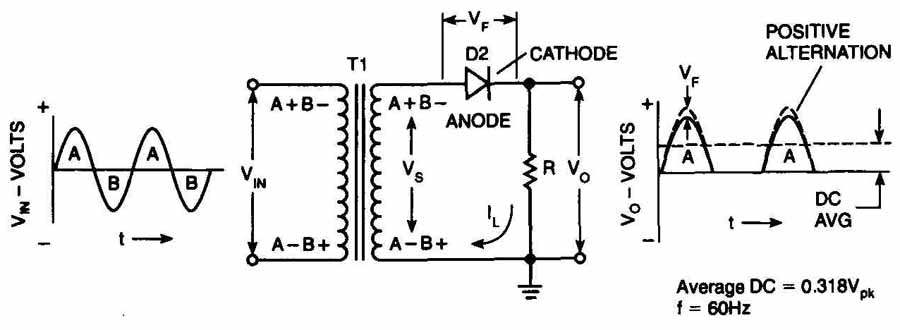
FIG. 9. A half-wave rectifier circuit.
On alternation A, diode (D1) conducts because its anode is more positive than its cathode. A voltage equal to the secondary voltage minus the diode’s forward-bias voltage (VF) is developed across the load (R). Alternation B appears as reverse voltage (VA) across the diode. To withstand this voltage, D1’s PIV must be greater than the alternation B’s voltage peak.
The output voltage is a series of 60 Hz, half-cycle alternations. The voltage is always in one direction and is known as pulsing DC. If the area under the positive pulses is averaged over a complete cycle, the average DC voltage is 0.318 times the voltage peak.
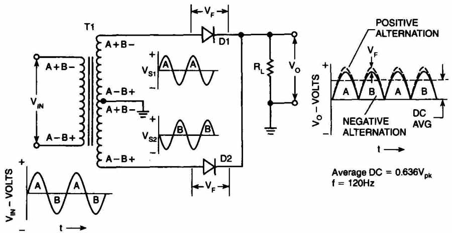
FIG. 10. A full-wave rectifier circuit.
Full-Wave Rectifier
The rectifier circuit shown in FIG. 10 is really two diodes and converts both alternations of the secondary voltage to a DC voltage. Therefore, it is known as a full-wave rectifier. A diode is in series with each secondary output and the center tap is grounded. The voltage between the center tap and each secondary output is equal in value, but 180-degree out of phase. When V is positive, V is negative.
D1 conducts during the A alternation, and 02 conducts during the B alternation. The center tap is a common return for the current from each diode. Because both diodes conduct current to the load in the same direction, the pulsating DC has positive half-cycles on both alternations of the secondary voltage. The output is pulsating DC at 120 Hz with an average DC voltage of 0.636 VpK.
Only half of the secondary is used at one time. Therefore, the transformer’s secondary output voltage must be twice that needed to provide the proper DC voltage. Also, each diode’s PIV must be at least the secondary’s (Vs) peak-to-peak voltage.
Bridge Rectifier
The bridge rectifier, shown in FIG. 11, uses four diodes in a bridge net work. One output terminal of the bridge network is a common ground for the return of the load current. The other output terminal is connected to the load.
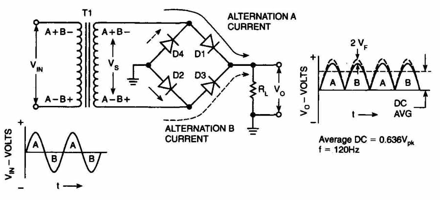
FIG. 11. A bridge rectifier circuit.
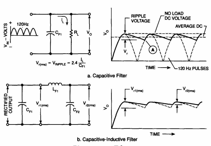
FIG. 12. Filtering
D1 and D2 conduct on the alternation A. D3 and D4 conduct on the alternation B. Both conducting paths deliver current to the load in the same direction. The pulsating DC output is the same as for a full-wave rectifier. The output DC voltage is the secondary voltage minus two forward diode drops. All of the diode’s PIV must be greater than the secondary peak-to-peak voltage (Vs).
Filtering
The pulsating DC output after transformation and rectification is not a satisfactory power source for most electronic circuits. The filtering function, shown in FIG. 12, smooths the output so that a nearly constant DC is available for the load. If there is excess ripple, the filter capacitor is not able to store enough charge to supply the required load and keep the output at a stable level. The ripple can cause the television to display symptoms such as hum or an unstable sync.
The pulsating DC output from the rectifier contains an average DC value and an AC portion called a ripple voltage. A filter circuit reduces the ripple voltage to an acceptable value. Resistors, inductors and capacitors are used to build filters. None of these components have amplification.
1. Resistors oppose current and normally function the same way in DC or AC circuits by not varying with frequency.
2. Inductors oppose current changes, and their inductive reactance increases with frequency.
3. Capacitors oppose voltage changes, and their capacitive reactance decreases with frequency.
Capacitor
A capacitor is made of two conductive plates separated by an insulator called the dielectric, shown in FIG. 13. The symbol found on a schematic is also shown in FIG. 13. When DC voltage is applied across the plates, electrons collect on one plate and positive ions collect on the other plate. The difference in the electrical charges on the plates equals the voltage applied to the dielectric’s lead. If the voltage is removed, the electrical charges remain in place and maintain the voltage difference between the plates. In this manner, the charge is stored by the capacitor.
This charge storage characteristic gives a capacitor in a circuit the effect of opposing voltage charges. For this reason, you can have two capacitors working against each other to smooth the ripple from the unregulated DC voltage. This is very important to the filtering function in DC power supplies.
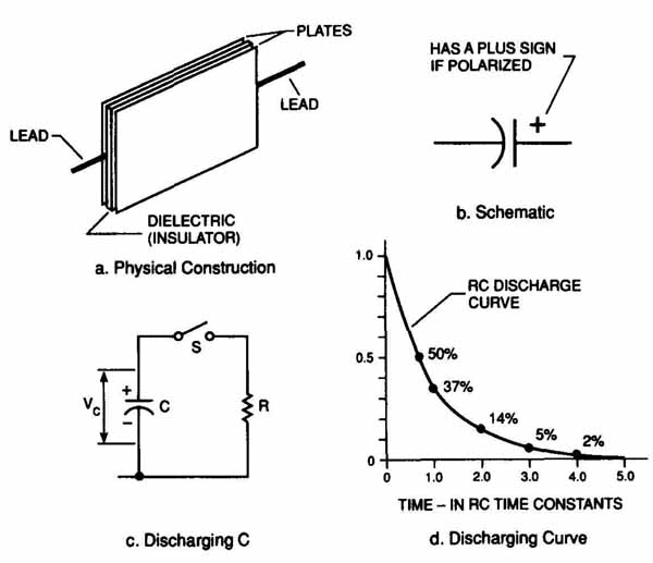
FIG. 13. Capacitors.
The electrical unit of capacitance is a farad. A farad is a very large quantity so actual capacitors are usually rated in microfarads. One microfarad is 0.000001 (1 x 10⁶) farad.
Troubleshooting Conventional Power Supplies
To troubleshoot problems in power supplies, you can use the following equipment:
1. DMM with a rectifier tester or a VOM.
2. Capacitance tester.
3. Isolation transformer.
First, look at the most obvious areas that may cause problems:
1. A hot chassis.
2. AC or DC line input.
3. Power line cord and plug.
4. Power switches are turned off.
5. Blown fuse.
6. Series resistive fuse.
7. Thermal overload circuit.
Then, look at other areas that you think might fail.
A problem with the power supply can cause the following symptoms. The television:
1. Is totally dead.
2. Makes a humming noise.
3. Has a small picture.
4. Blows fuses when turned on.
5. Has a vertically and horizontally unstable picture (also called a “breathing” picture).
6. Has black bars that drift from bottom to top.
Defects in the power supply that cause these problems are shorted diodes or filter capacitors, open diodes or filter capacitors, dropping resistors, fuses or switches, leaky filter capacitors or a shorted transformer or choke.
For example, 60 Hz or 120 Hz hum can point to a faulty filter capacitor. Faulty filter capacitors also can cause vertical rolling and horizontal tearing. You can use an oscilloscope to locate a bad filter capacitor by looking at the waveform. You also can jump another capacitor across the one you suspect as being faulty to see if normal operation resumes. If so, then replace the faulty capacitor. Each time you jump across a suspected capacitor, disconnect the power cord and discharge the jumped capacitor in order to keep from damaging solid-state devices.
After you have checked the possible causes and they are not the source of the problem, look at the circuitry more closely. Before you check the television’s internal circuitry, disconnect the television from the wall outlet. Just turning off the television is not enough. Then, follow the troubleshooting methods described in the section General Techniques for Servicing Televisions, in Section 3, The Basics of Troubleshooting to find the problem.
Locating Power Supply Problems
If a power supply fails, it might be due to a problem internal to the power supply or a problem induced by the operating circuit external to the supply. To check or test the power supply, perform these tasks:
1. Disconnect the circuit from the rest of the chassis. If the problem was not the power supply or damage to the supply components, the power supply output voltage should return to normal or somewhat higher.
2. Place an external load on the output to make sure the power supply functions properly under a full load.
If the power supply functions normally under a full load, the original problem is in another circuit.
If the power supply does not function normally, the problem is with the power supply.
If the power supply is defective, check the capacitors, resistors, diodes, transistors and inductors in the power supply. Use a DMM with a diode function to check the diodes and transistors. Also, remember that ICs are difficult to check. If the source of the problem is an IC, take careful voltage readings of all inputs to and outputs from the circuits in the IC, and of all components that connect the circuits.
If the components that connect the circuits on the IC appear to be working correctly, the IC itself is probably faulty. The usual procedure in this case is to replace the IC.
The half-wave rectifier’s circuits are normally protected with one or more fuses which are located on the main chassis. Fuses and silicon diodes present the most common problems in conventional power supplies. The fuse and diode can open if the components in the power supply in the connecting circuits are overloaded. When you replace a blown fuse, be sure to always use an exact replacement.
If the power supply contains a regulator with protective elements, there is probably no component damage due to the current overload because most three-terminal IC regulators are well protected internally. If there is no power supply voltage due to overload, the supply output should immediately return to normal when the external problem is repaired. If the regulator incorporates a thermal overload control that is tripped because of excessive power dissipation in the supply, let the power supply cool down before returning to normal operation after the source of the problem is repaired.
Other possible power supply failures include:
1. Loss of filtering due to capacitors that have changed.
2. Loss of output voltage because of a shorted output capacitor, open- circuited resistor or an open choke.
A failure in a power transformer, such as a shorted or open winding, would produce reduced output DC voltage or no voltage.
The main reason for IC regulator failures is too much dissipation in the internal series-pass transistors. If this happens, there will be no output voltage, but the input voltage will be normal. Also, if the output is shorted, there will be no voltage output because the regulator may have been shut down by the short-circuit protection provided internally.
Regulated Power Supplies
In most cases, a power supply must control its output voltage (or voltages) closely as its input voltage and output load are changed. This is called a regulated power supply. If the output was not regulated, the variations in its output voltage could become mistaken as signals within the system circuits being powered and cause errors, distortions, extra signals, and so on.
Most ICs require a precise power supply that controls the voltage levels within narrow limits. The supply must respond very quickly to peaks and dips in the current demand, because the ICs are adversely affected if certain voltage variations occur.
To design a regulated power supply, an unregulated supply, like those de scribed in the section Conventional Power Supplies earlier in this Section, is used and a regulator circuit is added to its output. The regulator can monitor the power supply output and automatically make adjustments so the output voltage stays within defined limits. A simplified regulated circuit is shown in FIG. 14.
To perform the required regulation, the regulator circuit varies the voltage (VREG) to keep the output (V constant as the load (RL) changes. If the load (RL) decreases, the load current increases. This tends to reduce the voltage output (V However, the regulator reduces the voltage drop (VREG) to offset the increase in current so that the voltage output (Vo) remains constant. Conversely, if the load (RL) increases, which tends to decrease the load current, the regulator increases the voltage drop (VREG) to keep the voltage output (Vo) constant. Similarly, the regulator increases or decreases the voltage if the rectified voltage drop (VREG) increases or decreases.
The sampling circuit monitors the voltage output (V and feeds a sample voltage to the error amplifier. The reference voltage generator maintains a constant reference voltage for the error amplifier regardless of input voltage variations. The error amplifier compares the sample output voltage to the reference voltage, and generates an error voltage if there is any difference between them. The error voltage is fed to the control element to control the value of the voltage drop (VREG).
The control element essentially acts like a variable resistor which is in series with the rectified voltage, R and the load (RL). When the rectified voltage or load (RL) changes, the input to the control element from the error amplifier adjusts this variable resistance to change the voltage drop (VREG) to hold the voltage output (Vo) constant.
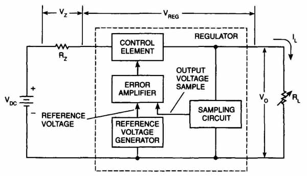
FIG. 14. A regulated circuit.
Severe transient voltage increases on the unregulated rectified voltage can be a problem with IC regulators. If the problem is severe enough, the regulator can exceed the maximum voltage difference allowed between the regulator input and the output. In some cases, regulator failure puts the full un regulated voltage on the load circuit. ICs are very susceptible to failure due to excessive voltage and can fail in large numbers in complex circuitry as a result. In some cases, you will find a zener diode across the regulator output that acts as a clamp at a predetermined level if the supply voltage becomes excessive. Thus, the power supply shuts down without damaging the system.
Switched-mode power supplies can be a significant source of electromagnetic interference (EMI). Shielding and filtering are used to keep any generated EMI from escaping.
Zener Diode
Zener diodes, shown in FIG. 15, are designed to maintain a fixed voltage across the diode junction and operate in the reverse breakdown region. When zener breakdown occurs, the strong potential across the depletion region causes a direct breakdown of the electron bonds, thereby freeing large numbers of electrons so a current can flow. The potential difference between the anode and the cathode is held constant and depends on how the diode was made.
Zener diodes are connected in circuits with their cathode as the positive terminal because they operate in the reverse-biased mode. Zener diodes are packaged in the same way as conventional semiconductor diodes. Small zener diodes are marked with a cathode band the same as conventional diodes. Large zener diodes are marked with the zener diode symbol, also shown in FIG. 15. In addition to having a voltage rating (reverse break down), zener diodes have a power rating that must not be exceeded.
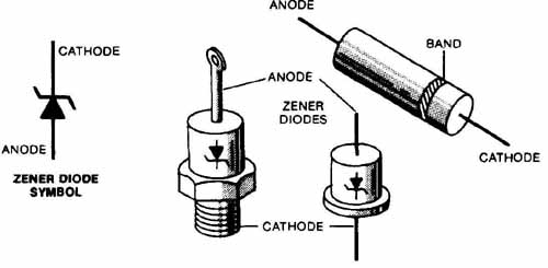
FIG. 15. A zener diode.
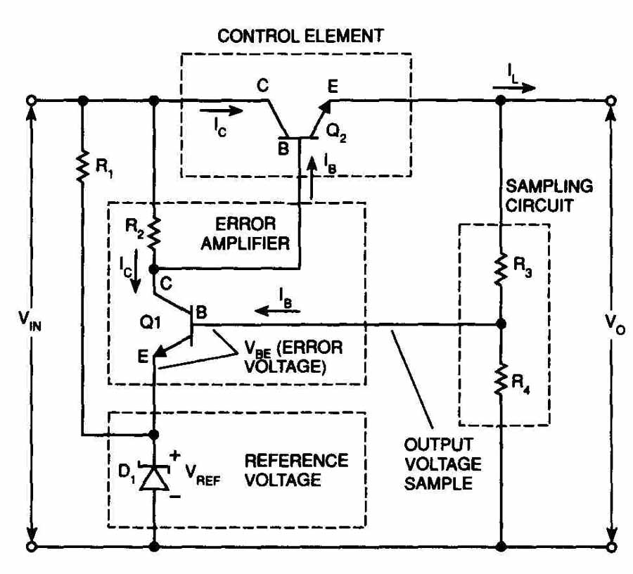
FIG. 16. A feedback regulator
Zener diodes are widely used as voltage stabilizers in circuits because the voltage drop across the zener diode is relatively constant. These diodes behave like regular diodes when connected in the normal way. However, they are not usually used this way. When connected in reverse and sufficient voltage is applied with a suitable current-limiting resistor, the diode breaks down in the zener mode and holds the voltage constant across it.
One use for zener diodes is to supply the tuning varactors with constant voltage. If the zener diode is defective, then the tuning will become inoperative or unstable. Zener diodes can also be used as signal devices to limit peak-to-peak pulses.
When you test zener diodes, a faulty diode can cause a horizontal bar to float up on an oscilloscope screen. Also, a defective zener diode can cause erratic voltage changes. In this case, monitor the output voltage carefully. If the input is steady and the output changes, the zener diode is probably defective. A shorted zener diode will cause the power supply to have no voltage. An open zener diode will cause the output voltage to be high.
Series-Pass Feedback Voltage Regulator
The feedback regulator, shown in FIG. 16, is a closed loop that feeds back a portion of the output voltage and compares it to a reference voltage. The difference between the two voltages determines the action that must be taken.
In the figure, the control element is an NPN transistor, Q2, which is connected in series between the input voltage (VIN) and the output voltage (Vo). The load current ( is the same as the collector current (‘s) to Q2. There fore, all of the load current must pass through Q2. Collector current (Ic) cannot flow unless there is a base current (IB) into Q2. This input to the base (IB) controls the collector current (Ic) and the load current (Ia).
In this circuit, a decrease in the load current ( tends to decrease the output voltage (V A decrease in the output voltage (V increases the base current (Ib) of the error amplifier which increases the collector current of the error amplifier. The increased collector current of the error amplifier reduces the base current from the control element. The reduced base current of the control element reduces its collector current, which increases its collector- emitter voltage. The increased voltage drop across the collector-emitter reduces the output voltage.
An increase in load current causes the opposite actions. Similar regulator control loop action occurs to keep the output constant if the input increases or decreases.
Troubleshooting a Series-Pass Feedback Voltage Regulator
When troubleshooting a series-pass power supply, use a voltmeter and measure the voltage at the output of the bridge rectifier to make sure the rectifier is operating correctly. If the voltage is not correct, you may have to repair the rectifier circuit. Check the reference voltage for the proper voltage; this voltage should remain constant. Then, check the error amplifier for proper voltages. Check the voltage on the base of the control element. Typically, the control element will be the faulty component.
Switched-Mode Power Supplies (SMPS)
Switched-mode power supplies, such as chopper, series-pass (linear), and self-oscillating, use switching regulators that can have a conversion efficiency of 85% or more. This efficiency results in lower power dissipation and smaller size components for a given power output. Other advantages of switched-mode power supplies are that they can:
1. Operate over a wide range of current and voltage.
2. Be used for the control element.
3. Have lower input voltage than output voltage.
4. Have output voltage that is opposite in polarity from the input voltage.
5. Have no off state, only on or standby.
Before beginning the troubleshooting procedures, make sure you are using an isolation transformer.
Switched-Mode Power Supply Operating Principles
FIG. 17 shows a block diagram of a switched-mode power supply. There are some similarities between switching systems and the regulated power supply system discussed earlier in this Section. The difference between a switched-mode and linear system is the action of an inductor used for temporary energy storage and how the control element is controlled to provide regulation.
If an AC source is used, the transformation, rectification and filtering circuits that provide a DC input voltage to the regulated power supply systems serve as a switching power source in switched-mode power supplies. If an unregulated DC source is used, an input filter may be required for ripple or noise reduction, or for stability.
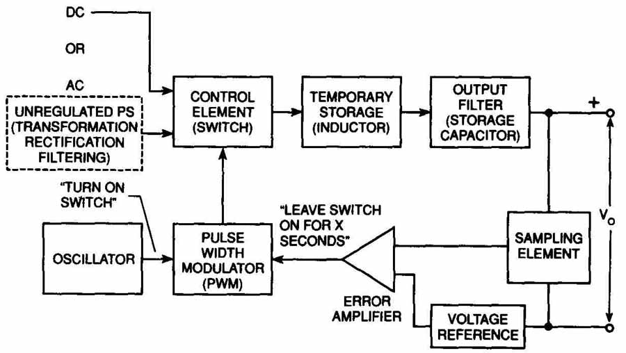
FIG. 17. A block diagram of a switched-mode power supply.
In regulated power supply systems, regulation is accomplished by varying the voltage drop of the control element. In switching systems, this function is accomplished by rapidly turning the control element on and off, and by varying the ratio of on time to off time. Unlike the series-pass control element, there is no linear operating state. The control element is either completely on or off.
When the control element is on, energy is pumped into the inductor’s temporary storage element in sudden bursts. When the control element is off, the stored energy is directed by a diode into the capacitor to supply the load as needed. The sampling element, reference-voltage, and error amplifier work in an identical manner to those in a linear supply. However, the output of the error amplifier is used directly to determine the length of time for the sudden bursts.
Compared to the linear system, the switched-mode system has three new circuits: the oscillator, the pulse-width modulator (PWM) and the temporary storage element inductor.
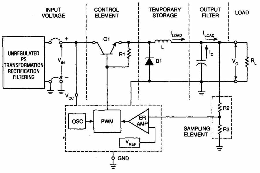
FIG. 18. A step-down switching power supply.
Regulators in Switched-Mode Power Supplies
There are three types of regulators:
1. A step-down regulator, also called a buck, is used when the required voltage is lower than the input voltage.
2. A step-up regulator, also called a boost, is used when the required voltage is higher than the input voltage.
3. A flyback regulator, also called an inverter regulator, is used when a regulated output voltage of opposite polarity is required.
FIG. 18 shows a functional block diagram of a complete step-down switching power supply. Each of the individual functions is discussed below.
Input Voltage
The input voltage for a switched-mode power supply can vary over a surprisingly wide range while still maintaining good conversion efficiency. An AC source is indicated for VIN. All the same design considerations apply for the transformation, rectification and filtering as for the unregulated supply described in the section Conventional Power Supplies, earlier in this chap ter. The ripple voltage filtering, which takes care of the 60 Hz and 120 Hz noise, can be somewhat less because of the output filtering of the switching regulator.
Control Element Switch
The control element switch is a switching power semiconductor. It must have low VON across it and must have fast switching times. It can be a single NPN transistor or a power FET, or it can be a combination NPN and PNP for higher gain operation. Regardless of the type transistor used, it is turned completely on (lowest resistance) during the ON time. Then, it is turned completely off (highest resistance) during the OFF time. It is used as if it were a relay, but operates at a very fast rate—from 20 kHz to 100 kHz. A 100 kHz wave has a period of 10 microseconds (0.00001 second).
Catch Diode
When the magnetic field of the inductor begins to collapse and release its stored energy, the energy must be contained and channeled in a useful direction. A diode called the catch diode performs this task in each of the circuits. It directs the stored energy into the output filter capacitor. The one way conduction of the diode is used to provide the proper circuit connection when the induced voltage across the inductor is the proper polarity. Due to the high switching frequencies in these supplies, the diode must have a very low forward voltage and a very fast switching time and recovery time. A Schottky diode is an ideal diode for this application.
Inductor
The inductor must have the proper inductance and must not saturate during its operation. The core must have a volume to handle the power required. If it saturates, it loses its inductance and its ability to efficiently transfer energy to the output. Remember, inductance is determined by the core material and the number of times the wire is wound on the core. Ferrite and powdered iron cores are usually used for switching power supply inductors. When iron laminated cores are used, they have core loss at higher frequencies, which lowers supply efficiency.
Filters
As in the series-pass regulator, the output filter capacitor stores energy to be used by the load. Because the output ripple frequency is much higher in the switched-mode regulator, the output filter capacitor usually is a much smaller value than that for the series-pass regulator. The input filter must reduce the 60 Hz or 120 Hz ripple to acceptable values, and it must keep the switching-frequency ripple from the input to keep the system stable and noise free.
Troubleshooting Switched-Mode Power Supplies
Normally, the switched-mode power supply circuit will turn off if it develops a short. If the circuit is open, the power supply will continue to output voltage but not current. In some televisions, if the power supply samples the high voltage and finds that the voltage exceeds its limits, or if the sensing circuit is faulty, the power supply will turn oft. Also, some power supplies have an undervoltage lock circuit that will turn oft the power supply if the AC or regulated outputs are too low.
To troubleshoot a SMPS, follow these steps; make sure you are using an isolation transformer:
1. Inspect the circuit carefully for defects and/or problems, such as burned components.
2. Make sure the standby power supply is operational, if necessary.
3. Disconnect the horizontal output transistor. This will allow service to the switched-mode power supplies with less loading. Then, start disconnecting the other loads one at a time, and check for shorted loads after they are disconnected from the transformer.
4. Remove the signal to the base of the switching transistor by disconnecting the transistor. This prevents the power supply from outputting power as you check the other circuits.
5. Monitor the DC voltage at the collector of the switching transistor as you slowly increase the AC input voltage. If the DC does not increase, notice the AC current draw. If there is no current, and no or low DC voltage, the unregulated power supply is open, there is an open safety resistor, or there is an open primary in the switching transformer. If there is no or low DC and the ammeter current increases, there is usually a shorted switching transistor.
6. Make sure the base has enough voltage from the standby power supply to start the SMPS.
7. Check the feedback circuit by turning the circuit on.
8. Connect a variable current limited power supply.
9. Connect a voltmeter to the input of the base circuit. If the circuit is operating properly, when you increase the voltage, you will see a corresponding change at the input of the base.
10. Repeat steps 6 through 9 for all of the SMPS circuits and different transistors until you locate the defective circuit or component.
11. If you have not found the defective circuit or component, you can reconnect the base voltage and continue troubleshooting using your normal voltage analysis methods.
Scan-Derived Power Supplies
Scan-derived power supplies use the horizontal output voltage being wasted as a supply potential. This energy is produced by the horizontal output be cause of the frequency at which it is pulsed and because it is oscillatory energy. This energy source can almost power the entire chassis, including the CRT.
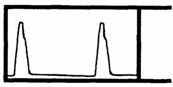
FIG. 19. A scan-derived signal waveform.
Note: Use care when measuring the voltage at the horizontal output collector unless you first disconnect the collector from the circuit. Many DMMs and oscilloscopes can be damaged by the high peak-to- peak horizontal waveform on the collector.
Note: When you use a variable line transformer, start with a low voltage and slowly increase the voltage.
The energy from the horizontal output eliminates the necessity for power transformers, and elaborate low-voltage supply circuits. This reduces the amount of heat generated by a power transformer, making televisions cooler to operate, lighter chassis, and reduces the cost of television production.
FIG. 19 shows the scan-derived signal waveform or pulse. The pulses are produced at retrace time, and the negative base line between the pulses is produced during scan time. If a rectifier is inserted in the circuit to allow conduction of positive pulses, the result is pulse rectification. If the rectifier conducts on the negative portion of the wave, the result is scan rectification.
The pulse voltage is usually greater than the DC voltage. Therefore, replace any diodes in the circuit with exact replacements. In other words, the diode cannot be reversed because the secondary windings would load down and the scan-derived circuit would not operate properly. Also, replace any rectifiers in the circuit with exact replacements that are capable of high-speed switching.
Troubleshooting Scan-Derived Power Supplies
If the television turns on briefly, then turns off completely, you may hear a short burst of audio when the television turns on. When this happens, the voltage regulator circuit senses the overload and turns off the circuit, which turns off the television.
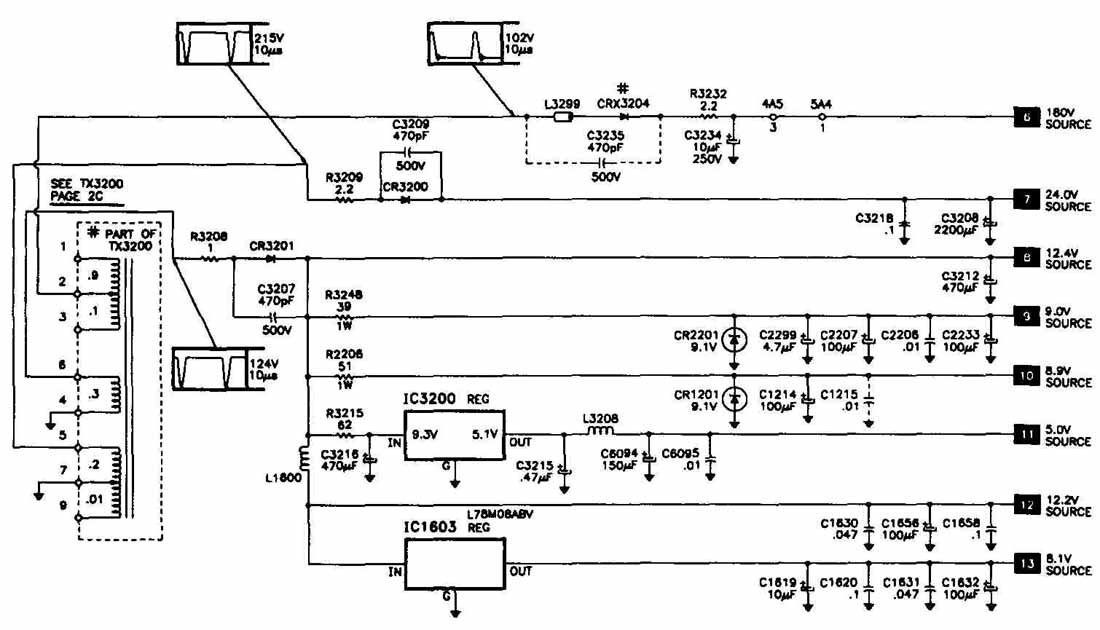
FIG. 20. Scan-derived circuits.
In newer televisions, the startup and secondary power supplies may be sup plied by the scan-derived circuits, as shown in FIG. 20. So, if the horizontal output circuit is not working properly, the chassis will not power up.
If this happens, follow these steps to locate the source of the problem:
1. Check all fuses.
2. Check the chassis for burn marks, including connections and components.
3. Check the boost source. If there is no boost, the source of the problem is in the power supply circuit. If there is a horizontal output signal, use signal tracing until you locate the faulty port.
Use a variable line transformer to reduce the AC input to 75V. Then, slowly increase the voltage until you detect the problem.
If one of the sources for the scan-derived circuits is not working correctly, measure the voltage at all connections and look for excessively low values. Do not turn off any DC voltage to the horizontal circuits. A low voltage measurement can indicate a defective or overloaded circuit. Shut down the chassis and disable the suspected power source. If the voltage on the other circuits increases, the scan-derived circuit you removed is defective. Troubleshoot all circuits supplied by this voltage.
Normally, if the flyback is faulty, all sources are bad or you will see arcing. Check for leaky or shorted diodes. Also, look for burned areas and poor solder joints.
Quiz:
1. What are the basic unregulated DC power supply functions?
2. What is the difference between a forward-biased diode and a re verse-biased diode?
3. What diode is designed to operate in a reverse-biased condition?
4. What type of power supply supplies power to the circuits before the set is turned on?
5. What are power supplies removed from the flyback called?
Key:
1. Transformation rectification, filtering.
2. Forward-bias allows current to flow through reverse-bias does not.
3. Zener diode.
4. Standby power supply