Soldering: The Basics --A thorough, enlightening primer on a vital topic.
by MARC COLEN
INTRODUCTION
Constructing audio equipment is a far from trivial task. The amateur faces most of the problems that plague large manufacturing concerns without the equipment and technical support available to such manufacturers. Consider the simple act of soldering.
A hot iron heats up some solder with flux in it and a good solder joint results. Or does it? Many large manufacturers of high reliability electronic equipment have found they need a great deal of money and effort to produce good solder joints. While the audio amateur does not have to concern himself with the details of the numerous military specifications whose subjects are solder and soldering, some basics are important. Let us consider first the solder joint and then the necessary materials and equipment to produce it.
THE SOLDER JOINT
Forming a solder joint involves a number of chemical and metallurgical processes.
The bond occurs when new metallic compounds are formed between the solder and surfaces being soldered. Called intermetallic compounds, they form a
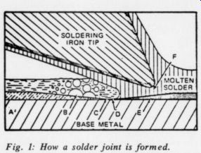
Fig. 1: How a solder joint is formed.
A. Flux solution lying above oxidized metal surface.
B. Boiling flux solution removing the film or oxide.
C. Bare metal in contact with fused flux.
D. Liquid solder replacing fused flux.
E. Tin reacting with the base metal to form a new alloy.
F. Solder bridge.
Note: Soldering iron tip shown not touching base metal for clarity.
continuous intermetallic layer between the solder and the surface (1). The formation of this layer, which may be only several atomic layers in thickness, is necessary if the solder joint is to provide the necessary mechanical and electrical integrity; solder provides no adhesive action. Fig. 1 illustrates the process.
Whether the intermetallic layer forms properly depends on:
1) the cleanliness of the metal surfaces; 2) their wettability; 3) the time; and 4) the temperature.
Flux, to be discussed later, provides for the first two. The last two, whose selection 7s at the solderer's discretion, are often given insufficient Attention. The higher the temperature, the thicker the resultant layer; similarly, the lower the temperature, the thinner the layer. The time effect is as one would expect; that is, the longer the connection is held at a high temperature, the thicker the layer, and vice versa.
A very thin, discontinuous intermetallic layer, typically associated with a cold solder joint, provides little integrity.
However, too thick a layer is also a problem. Intermetallic compounds, unlike the pure metals or simple alloys involved in electronic connections, have low ductility and the consequently brittle layer may be fractured by even the slight stresses associated with equipment construction. You should remove any gold on a lead, pre-tinning and wicking before soldering; the intermetallic compounds formed between gold, which is very soluble in solder, and tin will make the gold brittle.
The temperature required is somewhat dependent on the application. A solder joint must reach a temperature of about 450°F-550°F for the proper intermetallic growth to occur. Thus the iron temperature and head capacity must be able to provide that temperature in the minimum amount of time. Long time periods increase the possibility of device degradation and flux evaporation.
The time necessary for proper intermetallic layer formation is 2-5 seconds for the above temperature. Note that this is the time from when the soldering iron tip contacts the joint to when the tip is removed. The solder which should be applied to the joint, not to the soldering tip may be molten for slightly less time: that is acceptable and allowed for.
COMPONENT CLEANLINESS
The most likely materials for the amateur to have to solder are copper, tin, and occasionally gold. While the latter is...
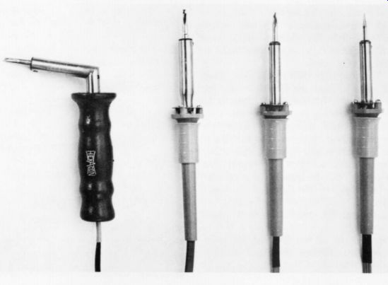
Fig. 2: Four irons of varying size.
...virtually immune to oxidation, both copper and tin oxidize instantly on contact with the atmosphere. Solder will not wet oxidized or otherwise contaminated surfaces. Other contaminants include the residue from smog, skin oil, and acids, hand lotions, and a virtually limitless number of other substances. Boards, components, stripped wire ends, and any other connections must be cleaned before soldering; flux will only handle the oxide layer.
An abrasive such as 3M's Scotchbrite is excellent for bare copper boards and may be used less sparingly on re-flowed solder coated boards. A clean tissue in rubbing alcohol will do wonders for other types of surface. Under no circumstances should you use brushes with brass (zinc is deadly to solder), abrasive papers, wire wheels, or other similar equipment: they will embed particles of the abrasive as well as the contaminant into the surface.
THE SOLDERING IRON
Choose your soldering iron specifically for the intended application. The input wattage, idle temperature, and thermal temperature gradient is 100°F-150°F between tip and connection. Therefore, the requisite tip working temperature is typically 550°F (best case) to 700°F. In practice, 600°F-700°F is optimum.
In order for the tip to reach and maintain the required temperature, the soldering iron must be properly matched to the job. If the iron is of inadequate thermal capacity, recovery time will be long and each successive connection will be at a lower temperature. Connections so formed will most likely be faulty. High thermal capacity does not mean that the tip temperature will be too high: the trade-off is rather the substantially increased weight and size of large capacity irons.
The temperature of most irons is determined by the Nichrome wire winding in the heater.(Figs. 1 and 2 illustrate several such irons.) Fig. 2 shows irons of varying thermal capacity and wattage. The largest, on the left, is suitable for soldering bus bars to a chassis but for little else in audio equipment. The others are all acceptable for general assembly use, although the smallest, on the right, might be inadequate for heavy transformer leads.
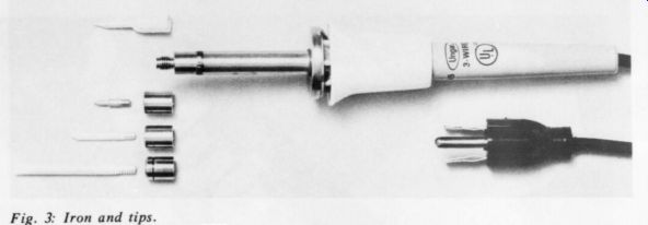
Fig. 3: Iron and tips.
Fig. 3 shows another typical iron. Details of the tip changing mechanism are obvious. You should be able to use a variety of tips with any iron you buy.
More expensive but more versatile are temperature-controlled irons. These actually sense the tip operating temperature and automatically control the power to maintain the preset temperature.
There are three basic methods of temperature control.
The first involves the use of magnets in the tips whose Curie temperature is the desired operating temperature. Because the magnetic field can induce damaging electronic fields and currents, I would not recommend this type of iron. The second method is somewhat more sophisticated, using a thermostat in the heater to control the temperature. Fig. 4 shows an iron which uses this method. The tip temperature may be altered by changing heaters. Proper tip grounding and spike suppression make less likely but do not preclude the destruction of sensitive devices.
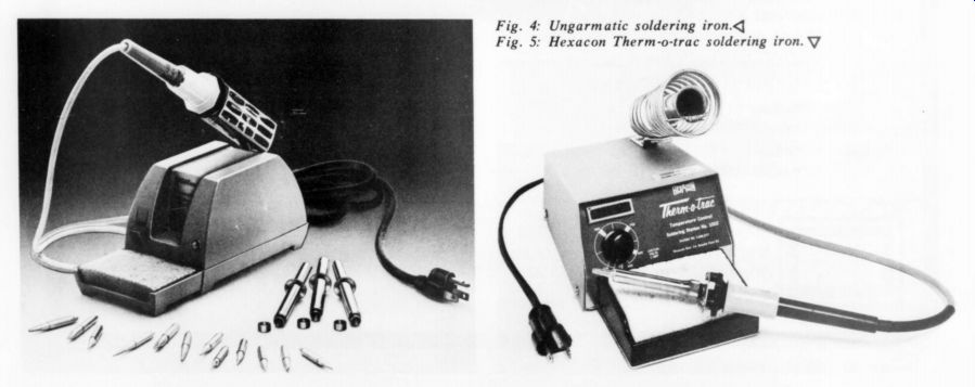
Fig. 4: Ungarmatic soldering iron. Fig. 5: Hexacon Therm-o-trac soldering
iron.
The last method is much superior to those so far discussed. It involves a thermistor in the tip (but not attached to it-the tip must be easily removable) connected to an electronic controller. Fig. 5 shows this type of iron. This particular one, the Rolls-Royce of soldering irons, provides for temperature variation at the twist of a knob and, by zero voltage switching, no spikes, fields or leakage at all. Further, its input wattage is twice that of the others mentioned, making it more capable of handling diverse tasks.
Although expensive, the Therm/o/trac iron is worth the money in capability and reliability. If you can afford it, buy it.
THE SOLDERING TIP
The proper tip configuration transfers the most heat from the soldering iron heater to the connection being soldered. The tip should be as large in diameter as possible while still slightly smaller than the connection being soldered. Fig. 6 shows some of the many types of tip available. To prevent an excessive thermal gradient, the length should be no greater than necessary to reach the connection. The proper choice permits heating the connection rapidly without damaging components or board circuitry.
Keep the iron tip well tinned for best performance and longest life. If you use a dry tip, there will probably be just point or line contact between tip and connection; very little heat will be conducted. If the tip is tinned, that is, coated with a thin layer of molten solder, then that solder will be a bridge between the tip and the connection to be soldered. The tremendously increased cross section forms a very efficient heat transfer path.
The second reason to keep the tip properly tinned is to lengthen its life.
Virtually all tips are machined from copper, which has high thermal conductivity. Unfortunately, copper is highly soluble in tin. Molten solder will dissolve a plain copper tip, and the dissolved copper will form brittle copper-tin intermetallic compounds. For that reason, a thin layer of a metal relatively insoluble in molten solder is plated onto the copper tip. Iron is generally used because solder will set to the iron surface but not dissolve it.
Iron is a much poorer thermal conductor than copper; therefore, the plating must be as thin as possible. It also oxidizes readily, especially at high temperatures.
The oxide layer is not self-protecting, so oxidation will proceed until the entire tip is iron oxide. Iron oxide is not wet by solder and is a poor thermal conductor.
You can often salvage oxidized tips by cleaning them with a very fine abrasive, such as 600 grit paper.
To prevent tip burnout, keep the tip tinned. The tip must especially have a good layer of solder covering it while it is idling in a holder, so never wipe the tip on a wet sponge just before returning the iron to the holder. Rather, add solder, removing only the excess by Wiping on a wet sponge. Dross is acceptable so long as solder is immediately added.
Even with the best of care, tips will eventually wear out. The iron plating is slowly dissolved by solder and abraded by mechanical contact with leads, etc.
Eventually the iron plating breaks and the underlying copper is quickly attacked.
You will usually see blistering on the tip surface. When that occurs you will have to replace the tip.
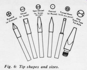
Fig. 6: Tip shapes and sizes.
SOLDER
Without delving into the metallurgy of solder, let us quickly consider its basic nature. Solder for the electronics industry is usually a mixture of tin and lead in the proportions of 63:37 or 60:40 for the tin and lead respectively. Small amounts of trace metals are typically found and antimony is usually added to avert ''tin pest." As far as the amateur is concerned, there is little difference between the two and you may use either. These solders melt at approximately 360°F.
For special purposes, other solders become useful. For example, there are high temperature / high strength solders, low temperature solders, solders for aluminum, etc.
--------------
About the author
An aerospace material scienctist and consultant. Recent work in military-grade soldering, and he has presented and published a number of papers in the field, He is also an avid audiophile and a member of the Society of Audio Engineers. Questions accompanied by a postpaid return envelope should be directed to Box 1225, Canoga Park, CA 91304.
For a nominal fee the author will supply small quantities of special fluxes and solders to interested experimenters. Send postpaid envelope for list of available materials.
----------
FLUX
Flux has two primary functions. First, by reducing oxides, it provides tarnish-free surfaces and keeps them clean. Secondly, it improves the wetting action of the solder.
Chemically there are three major types of flux: rosin fluxes, organic acid fluxes, and inorganic acid fluxes (in order of increasing chemical activity). Rosin fluxes are most usual in the electronics industry and are the type used in the core of cored wire solder. They are the most popular because they do not corrode at room temperature so do not have to be removed.
Activated rosin flux is used in some cored solders, but if not removed in highly humid environments it may be corrosive.
Removing activated rosin flux requires complex organic solvents and I will not discuss it here.
Organic acid flux is substantially more active than any rosin flux. It is a liquid and can be easily washed away with water.
This flux is ideally suited for large, automated soldering machines with in-line aqueous cleaners, but is not suitable for most amateur work.
Inorganic acid fluxes are stronger yet.
They are typically liquid, though some are paste; and are water-soluble. An example of a rather impure inorganic acid flux, not suitable for electronics work, is plumber's flux available at your local hardware store.
Only rarely will the amateur need a flux stronger than that in his solder, but for special purposes other fluxes are useful.
For example, soldering military surplus devices with heavy oxidation requires strong flux, as does soldering to steel.
CONCLUSION
While soldering is not the biggest problem facing the audio amateur, making the best solder joint possible is good sense.
Reliability, minimum component damage, and long tip life are objectives worth considering. A little care and effort are all you need.
Reference
1. Colen, Marc, "Tin Plating for High Reliability Soldering," Elec. Pkg. & Prod. April, 1978, pp. 162-165.
-----
Also see:
Direct Metal Mastering-- A New Art In LP Records (April 1987)
The Suppression of Surface Noise, by D.T.N. Williamson--A classic which laid down constraints for all today's quieting systems.