Departments
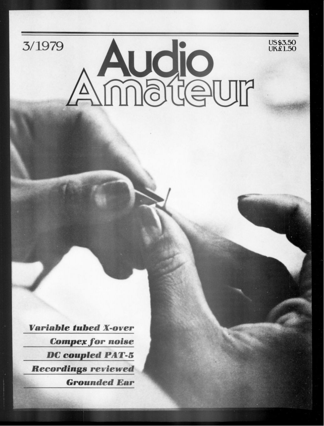
COVER MYSTERY--The hands-on cover action involves a stylus assembly--but that's all we're prepared to say about a photograph the editor took years ago while on an over-the-ocean trip. A two year subscription to anyone who can identify the cartridge, the manufacturer, and the location of the plant.
- About the issue (Intro)
- Showcase, Robert L. Doughty, A vacuum turntable with glass platter
- Editorials
- Audio Aids, by readers Banks, Branam and Boutin, On a preamp, dents in tweeters, and 198A hums.
- Book Reviews--About a new series on basic do-it-yourself audio, by Ron Miller
- Recordings Review, Reels vs. some D-to-D, Dolby , and Nipponese chamber music
- The Grounded Ear--An old title, a new feature and new trends in audio, by Peter Sutheim
- Classic Circuitry--The Dynaco PAS-2 preamp
- CORRECTIONS
- LETTERS
Showcase
MY RECENTLY DEVELOPED TURNTABLE features vacuum to hold the recording flat against the platter which is a disc of glass (the mirror-like turntable top). With the record thus held, warp, wow and many associated problems disappear. Highs are improved as well since the record surface is rock solid The table is two-speed, belt driven by a hysteresis synchronous motor. The platter is machined aluminum and the whole assembly, including the glass, weighs about 14 pounds. The four discs at the corners are spring mounts and were arranged to support at the center of gravity.
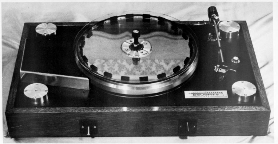
I have made several models. One uses a DC two-speed motor and another, under construction, is direct drive.
The vacuum is supplied by a remote, silent pump in a separate enclosure. This design makes clean records and platter surface a must. The platter system design is covered by patents. I welcome reader opinions on such a system.
[Please send comments to Mr. Doughty in care of TAA .Ed.]
In my opinion, a flat record also offers advantages relative to tone arm effective mass. On my table and arm, which I also designed and built, I have increased the effective arm mass to 70 grams and use a brush to help sup port it.
Robert L. Doughty; West Hartford CT 06107
MORE BEAUTIES? How about sharing your handiwork with others? Photograph that project of yours (in black and white, please) and send it along to TAA's department for beautiful craftsmanship. We'll be pleased to showcase your workmanship too.
About the issue
FROM THE PUBLISHER
All of us recognize by now that inflationary pressures are steadily eroding the value of the dollar. Everything costs more. I am sorry to announce a price increase for 1980. The good news is that you can still subscribe to TAA for the next two years at the present prices. The new prices will not go into effect until December 1, 1979. Unfortunately we cannot accept subscriptions for a longer period. Our first issue of 1980 will go into the mails the week after Christmas, 1979.
Thanks to all of you who took the time to write about advertising policy changes. We are increasing the advertising ratio to 40% beginning with this issue, where advertising levels are making possible an additional eight pages. Average advertising levels in U.S. magazines are now between 55 and 65%.
This issue is also the first produced entirely with our new typesetting capability. It increases the text density in many cases so that we will actually be delivering more material in the same number of pages. Estimated percentages are not simple to compute but conservatively a typical page now contains at least 10% additional material.
We are enclosing a tear-out card in this issue as well.
Growth has been slow, despite our promotion efforts and your assistance. We are again asking you to help us attain the circulation growth we need to increase the number of issues. We would be happy to produce five issues in 1980 but we can only do so if our circulation rises significantly. That means something near 2,000 new subscribers. We will close out 1979 with nearly 8,000. If you can help us find more people like yourself-or those with a potential interest in a new hobby, then 7AA can become the first magazine with a metric publishing schedule.
We regret the increase in cost as much as you do. We hope every one of you will act now to get your subscription renewed before the December 1 deadline.
Seventy two pages make up this jam-packed issue including two new features, a mysterious cover, and several interesting newcomers among our advertisers. Brian Waldron leads off with a variable crossover using tubes. The text, photos and graphics are all Waldron's work. He has other tube projects and instrumentation in mind and will welcome reactions from the tube buffs. Reggie Williamson's article (p. 12), waiting to make its appearance on this side of the Atlantic until it could grace the pages of Hi-Fi News & Record Review in Britain, follows up on Walt Jung's and Craig Todd's introductory piece on the Signetics 570/571 chips (TAA 4/76).
Reggie's influences also included a strong interest in dBx and developments that have led at last to release of the dBx encoded disc recordings. His Williamson Compex, while not a dBx system, is a fine version of noise control for amateurs.
Walt Jung and Dave White are back this time (p. 24) with a monumental article on preamp design. Their first effort (TAA 1/7 ) made many changes in Dyna's PAT-5, but this latest one is a really far-reaching exploration into audio's un charted zones, out beyond the instruments. Jung and White have both been improving their sound systems significantly and the more they upgraded, the more they were able to hear.
After their systems were reasonably clear of what they call 'masking effects' they turned again to their PAT-5/Wj-1 and set to work. Step-by-step they made changes that improved the sound, whether they could meter any change or not.
We expect their article to have wide repercussions. The range of differentiation which they can detect lying beyond the reach of instruments and standard tests is far larger than most have evidently heretofore supposed. This does not mean that henceforth this magazine has a new policy of subjective testing exclusively. Nor have Jung and White moved to such a position. Either/or answers are always too simplistic for the kind of world we inhabit.
The results Jung and White report need testing by as many of us as can take up soldering iron, side cutters, and their suggestions, build a modified PAT-5/W J-1A and listen critically and comparatively. Then share the results. Armchair speculation is too plentiful and too cheap. We hope to report from other evaluators in the next issue who have had a chance to hear versions of the PAT-5/W J-1A. We also hope other periodicals may give some attention to this effort. The object is not to establish reputations for the authors or this publication: the object is to explore some reliable techniques to achieve better sound.
Authors Rod Reese and Ron Shaffer offer some experimental evidence gleaned from their explorations into psychoacoustics. Their article, (p. 36) proposes an interesting thesis that hearing and conscious intention may be more closely linked than we have supposed.
Several months ago we began to ask recording companies for samples of their tapes, digital, and D-to-D products and to send them along to our editors for comment. We thought you'd like to hear about the best of them (p. 49). Fred Gloeckler offers some interesting data on correct Dolby adjustments, as a bonus. Reg Williamson adds a viewpoint or two from East Anglia.
Peter Sutheim, an experienced hand in electronics generally and in audio particularly, has agreed to shoulder the task of TAA's reporter-at-large on developments in the audio scene.
His first offering, written en route to a vacation after the June CES gathering in Chicago, begins on page 54.
Three faculty members at the University of Waterloo in Canada published a letter in issue 2 (letters p. 52) advancing the thesis that if polarity, RIAA equalization and overall gain of two preamps are carefully matched, no difference in their sound can be detected. Their letter has inspired a flood of correspondence. So important (and lengthy) is it that we begin it on the page facing and continue it on page 58 in our all too brief Letters section. We regret the inability to use more of the replies received.
WE WELCOME SOME NEW FACES
In our advertising roster this time. The great majority of TAA advertisers, with few exceptions, are smaller enterprises based on a small group's energy and skill. Their products more often than not show imagination, dedication, and better than average quality. We like being a publication such efforts can afford. And we think our advertiser's use of 744 says something about their attitude toward audio: an enthusiasm not far from your own as readers.
It is a risky thing to try to be a small business today. Two of our former advertisers have folded tents, regretfully, and closed shop: Speakerkit of Menomonie, MI, an undertaking of unusual quality and imagination who will be missed, and TSR Engineering who had a disastrous fire over a year ago and unfortunately never really recovered.
As we have come to know those whose efforts are advertised in our pages we have been impressed again and again with the unique character of most of their offerings. There may be money grubbers among them, but if so, it is hard to detect.
For most, the motive force is the pleasure of a good product. I commend them to you.
------------
Audio Aids
PAINLESS PREAMP
For several MONTHS I have been listening to (and experimenting with) a spectacular preamp that cost me about $110 and no more than two hours to put together. Most readers could do the same and beat the sound quality of just about any preamp under $1000. To create my preamp I took a PS II phono stage amp and ran it through attenuators directly into the power amp.
The PS II is available for $119 + $5 shipping from PS Audio, 1529 C Stowell Center Plaza, Santa Maria, CA 93454 (it was only $89 when I bought it). It is sold as an add-on substitute for your preamp's built-in phono stage (it plugs into a tuner or aux input) and beats the phono stage of most preamps by a wide margin-the Mark Levinson is the only exception I know of. Since it has 40dB of gain and will feed a 6008 load, a line amp is unnecessary in most applications.
The PS II does, of course, need attenuators instead of ordinary pots for the volume controls (see TAA 2/72, p. 14 for a construction article for stepped attenuators), but any good quality pot will do for the 100k balance control. A simpler circuit that would work well would eliminate the balance control and gang the two volume pots to give easy control of the balance between the channels as you change volume. The 3.3k resistors are needed only for some power amps; they eliminate the possibility of a near-short across the power amps input at low volume. Some amps develop sonic aberrations when the input is brought near ground potential.
Probably the only pitfall for the novice constructor is the possibility of hum. To avoid such a problem make sure the shield for your attenuator box's output cable is connected to the input cable shield with no more than 1' of wire in open space. Make sure all signal carrying wires are shielded, use a common grounding point to prevent ground loops, and in general follow Taylor's ad vice (TAA 3/74, p. 15) to avoid hum problems. You may have to experiment a little to get rid of hum, but with Taylor's article and a little common sense you will be able to eliminate it altogether.
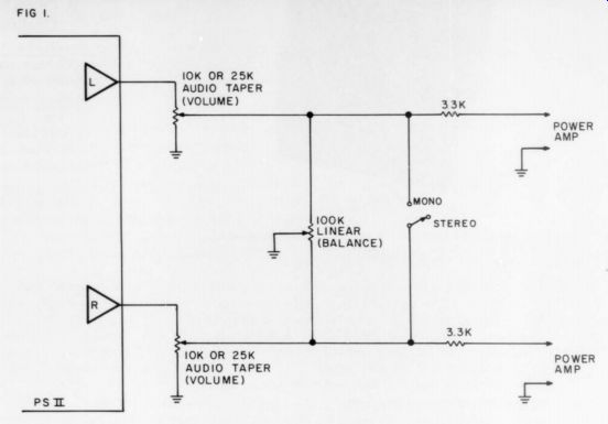
FIG 1
A few readers will need a line amp because of long amp-preamp cables, a low-output cartridge (ADC XLM's and Shure V15's will work well, as will most similar designs), or an insensitive power amp (i.e., an amp that needs more than 1.5V input for ear-splitting volume with your speakers). Other readers need tone controls. Interposing a graphic equalizer between the PS II and the amp will answer both needs for most users. With a Dynaco, Ace or SWTPC equalizer one could put together a very unusual preamp for $200-$300. If you need only the line amp, try the Morrey super buff (TAA, 4/77, p.18) or, if you need some gain and not just impedance matching, you could build the circuit in Fig. 2
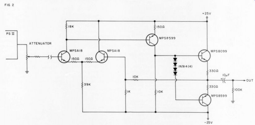
FIG 2
Paul McGowan and Stan Warren of PS Audio designed this circuit. I have not heard it, but they claim it is as transparent as the PS II. I understand PS Audio will soon introduce a line amp module based on this circuit to match the PS II.
WILLIAM P. BANKS Claremont, CA 91711
RESHAPING DENTED TWEETERS DESPITE ALL PRECAUTIONS, it does hap pen that the fragile hemisphere of the familiar “fried egg ” tweeter gets dented or crumpled. If, for instance, you remove factory installed protective screens or grilles in order to improve high frequency performance, the tweeter is vulnerable to a misplaced thumb. So it was with me and a 1971 Advent.
At first there seemed no remedy except replacing the tweeter, because any attempt to work on the dent risked enlarging it, or cracking the light plastic material, or destroying the voice coil alignment. Fortunately, the depressed area involved only a quarter of the surface and did not conspicuously affect the sound. The Advent stayed in use until I had an idea. The remedy is harder to describe than to do, and any reader with such a problem should examine his particular unit closely, taking my solution as a general guide that may require adaptation.
First, buy some “Bud” typewriter cleaner; it is a soft reddish putty on a plastic handle. Tear off a small amount.
Shape it as nearly as you can to match the contours of the whole tweeter dome, including the indented area. Do not press it onto the tweeter: that could cause worse damage. With an eye on the tweeter, mold an approximate “cap ” for it with your fingers. Do not warm the putty to increase pliability or it may become too sticky.
Mount the flat side of the putty on a strip of wide masking tape. Then fit the putty cap gently against the tweeter dome, holding it in place with the masking tape. Take care that the tape does not stick to the "surround" of the tweeter or to fine wires and other fragile parts.
Choose a record with clean, solid, heavy repeated transients. Play the passage two or three times at a healthy volume level. Carefully peel the tape loose and lift off the cap. If the dent was not too large or sharp, you should see that a good deal of it is gone. Repeat the process, each time reshaping the putty to fit the changed contours. Eventually the tweeter dome will resume its proper shape.
If any putty residue sticks to the tweeter surface, remove it with a fine needle. This is delicate work, but if you place a clean, dry needle sideways against the specks of putty and rotate it, you can roll them onto the needle without harming the tweeter surface.
DONALD BRANAM Chico, CA 95926
GETTING THE HUM OUT OF A 198A
I'M GLAD TO REPORT I am the proud owner of a 198A preamp.
I wasn't always proud of it. My audiophile friends used to make such comments as, “It hums because it doesn't know the words-ha ha!”No matter how effortlessly it handled the most demanding program material you could put through it, you could never claim it had no coloration of its own; in fact, to use an old radio amateur's expression, it was “humming to beat the band. ” While the hum was almost bearable in the tape, tuner, and aux. modes, it was totally raucous in the phono and mike modes.
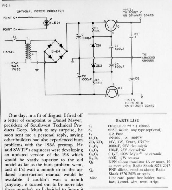
Fig.1 OPTIONAL POWER INDICATOR
Fig. 2
One day, in a fit of disgust, I fired off a letter of complaint to Daniel Meyer, president of Southwest Technical Pro ducts Corp. Much to my surprise, he soon sent me a personal reply, saying other builders had also experienced hum problems with the 198A preamp. He said SWTP's engineers were developing an updated version of the 198 which would be vastly superior to the old model as far as the hum problem went, and if I'd wait a month or so the up dated construction manual would be available. I couldn't wait a month (anyway, it turned out to be more like three months), so I decided to figure it out myself.
The noise largely consisted of 60Hz hum, with a small dose of 120Hz, some high frequency power line harmonics, and assorted R.F.I. components from the Ten-Four Good Buddies. So after a bit of head scratching and trial and error box, 3-cond. wire, term. strips I came up with the following modifications, which are quite simple, cost less than $10, and reduced my audible noise in the phono and mike modes by about 15dB.
---------------------
PARTS LIST
Original or 25.2 § 100mA SPST switch, any type (optional) 14 A Fuse 1N4002, 1A, 100PIV 15V, IW, Zener, 1N4744 1000pF, 25V electrolytic 470uF, 25V electrolytic C;,Ce 0.1uF, 100V Mylar or ceramic RR; 68012, 5 W resistor ohm, NPN silicon transistor 1A or more, 40 or more volts; Radio Shack #276-2017 Q, PNP silicon, rated as above; Radio Shack #276-2025 or equiv. Line cord, panel fuse holder, metal ZD,,ZD, C,,C C,;,Cy
-----------------
1. Construct a new, regulated power supply in a separate enclosure located several feet away from the preamp. You could take most of the parts from the original power supply, but I don't recommend it unless you enjoy prying up and de-soldering components from previously assembled circuit boards. I reused the power transformer only, and assembled the circuit on terminal strips.
2. Make an iron (soft steel) cover to fit inside the wooden one and shield the circuitry from induced hum pick-up and R.F.I. You can make this from any stock you have on hand up to 1/16 ” thick; naturally from a shielding stand point the thicker the stock the better.
3. Remove or disable all wiring AC power. This means the original power switch will be inoperable; make or buy another power switching box.
4. (Optional) Replace the original neon power indicator with an L.E.D. and dropping resistor.
Since the 198A preamp is only available in kit form, I assume you are somewhat familiar with its circuitry.
Fig. 1 is the new, regulated supply; Fig. 2 is the cutting and bending plan for the shield cover.
SWTP's new model of the 198A solves this problem in slightly different ways; in addition, they have made other minor differences in design and components. I feel my modifications are most easily incorporated into older units because they require no major component replacements.
Some may question my removal of all AC wiring from the unit. Let me just say I tried every alternative, including rerouting wires and placing internal shields between AC and signal wires.
Even running the preamp on batteries did not help until I removed all the AC wiring.
A final note: be extremely careful to watch polarities. And if your preamp uses the op amp modules with DC balance controls, you may have to read just the DC balance according to the factory instructions, because the voltages will now be 0.7V lower.
LEONARD A. BOUTIN
Taunton, MA 02780
BOOKS
By Ronald H. Miller
I BEGIN THIS REVIEW with a sense of bemusement over how far The Audio Amateur has developed with the years.
When I became a subscriber with the first issue we were being introduced to a new and different approach to the audio hobby.
Reading through recent issues I question how newcomers to the magazine can still be beginners and deal with the articles published. We regularly need to find basic books which reopen the field.
Hayden Books has imported a useful series from the English publishers, Newnes: Newnes Constructor's Guides.
These six volumes ($5.25 each) go a long way to help beginners get in on what we are trying to do. The publisher is not clear which is first in the series and which is last; the following is my guess at the most helpful sequence.
Electronic Diagrams, by Morris A. Colwell, is an introduction to those strange pictures known as circuit diagrams. No right thinking person would connect a wavy line with a unit of resistance, nor parallel vertical lines with a value of capacitance' Even when one has grasped the basic principles involved, the variations on such basic symbols need to be explained.
Colwell takes his readers from the various ways of indicating connections through passive components, electro mechanical devices, hot and cold cathode tubes (called in British idiom 'thermionic valves and cold cathode tubes ”), integrated circuit logic devices, transducers, and miscellaneous symbols. Chapter 8, next to last, deals with a more general subject in that it shows the way “black boxes ” and block diagrams can portray the interrelation of basic circuit elements discussed in earlier chapters.
The last chapter briefly covers a variety of topics: the way logical diagram layout compares with a bird's nest style of construction, direct coupling, power supply voltage decoupling, power amps, op amps, filters, oscillators, various multi-vibrators, and general power supply circuits. The coverage Colwell gives these topics will not allow a novice to understand a circuit and how it operates, but he does provide general coverage of what those “squiggles ” represent. The beginner is likely to find such a discussion helpful if this book is one part of his studies.
In Electronic Components Colwell carries our fledgling hobbyist further into building electronic projects. The first chapter, “Getting Started,' introduces the appropriate tools, soldering technique, and a few other basics. Subsequent chapters give basic information about types of components and their specifications: resistors, capacitors, inductors and transformers, semiconductor devices, integrated circuits, electro-mechanical devices, etc. An appendix gives other useful data such as abbreviations and wire sizes.
The detail given is useful but not over whelming, and exhaustive treatment is better saved for someone who is ready to find more thorough coverage in more detailed books. Colwell's discussion of components should be helpful for someone getting started in electronics. I had never seen his mnemonic for the resistor color code before: “Bye, Bye, Rosie, Off You Go, Birmingham Via Great Western. ”'Before this revelation I had simply memorized (7) the arrangement of colors in the spectrum and tried to keep straight the additional colors at each end.
My introduction to this series came through Printed Circuit Assembly by M. J. Hughes and M. A. Colwell; which I couldn't stop myself from buying when I found it in a bookshop. Anyone who has a chance to build electronic circuits in these days knows something about printed circuit boards, but beginners don't have information about the details of their design and production; Hughes and Colwell give a good introduction.
Chapters are titled; “How and Why Printed Circuits are Used,” “Board Materials and Their Characteristics, ” “Planning a Printed Circuit Layout, ” 'Processing Techniques,' Component Assembly, ” “Manufacturing Techniques, ” and “Alternative Proprietary Boards. ” The first chapter includes with its general discussion and illuminating look at techniques for making double-sided boards. Board material characteristics and the electrical characteristics of various copper tracks are valuable parts of chapter 2.
Chapter 3's discussion of planning PC boards is the reason I bought the book: it is well worth the price of the whole volume. My problem is that of many readers: here is a circuit I would like to build, for example Jung's informative Op Amp Cookbook, but no one tells me how to get that headphone amp diagram translated into the real world. This chapter should help the transfer even though such an introductory discussion will have to be supplemented by practical experiences (including some mistakes).
Chapters 4 and 5 continue the useful discussion of how to make and use circuit boards. The overview of proprietary boards gives information about other techniques of wiring, although one might wish for a discussion of wire-pencil or wire-wrap techniques. This is an in teresting and useful volume.
Next in sequence P. C. Graham in Simple Circuit Building takes the basic material of the first three books and gives practical experience with a number of simple circuits. The first chapter builds on the analogy of traffic control to develop a simple two-transistor switch with schematic diagrams and a practical wiring diagram before treating bi-stable and multi-vibrator circuits. Separate logic modules are built in chapter 2 with simple circuit board layouts; and various standardized logic circuits are covered in chapter 3.
Linear ICs are introduced in chapter 4, their various applications being outlined with a suggested board layout. (Figure 49b simply duplicates 49a rather than showing an inverting amp as the caption indicates.) Op amp and timer circuits are both given basic introductions. Chapter 5 contains a good discussion of the theoretical and practical aspects of DC power supplies.
The sample circuits discussed are supplemented with parts layouts and wiring diagrams.
Chapter 6 contains an introduction to AC amplifiers. Discrete transistor bias stabilization with AC signals using DC feedback techniques and principles of layout with some simple guidelines, form the first part of the chapter. The discussion of various audio ICs in the rest of the chapter does not give enough detail to be useful. An appendix gives parts lists for those illustrations which did not include all the values. Simple Circuit Building is a good way to get basic experience with electronic circuits.
Colwell then takes the beginner one stage further in Project Planning and Building and provides some useful suggestions for those who have been in the craft for some time. Chapter titles ( “Planning, ”' 'Working with Tools,' “Component Board Layout, ” 'Case Design and Layout,' “Case and Chassis Construction,” and “Assembly and Wiring ”) represent the process through which any project more rudimentary than a commercial kit must be taken.
Even TAA projects leave the hobbyist to settle at home questions of case design and layout, chassis construction, and putting it all together. Most of my own projects primarily run into difficulty here.
Colwell's book gives useful help with these questions even though it does not give simple ABC answers to the questions you must answer when “rolling your own. ”' I don't know of a more helpful treatment of the questions we all face when we have that nice assembled circuit board, potentially so useful but absolutely worthless until cased and connected to the outside world.
Colwell ignores commercial projects and concentrates on such useful things as a step-by-step discussion of designing and working your own chassis. His lists of tools for circuit and chassis building are also useful. The appendix contains various tables, dimensions of screws, drill sizes, math tables, etc.: and several suggested layouts for circuit board planning charts.
This book should be helpful to many TA readers. A. C. Ainslie joins Colwell in the final book of the series, Practical Electronic Project Building. The preceding books are here brought to fulfillment in a very useful overview accurately described by the title.
Tools, workbench layout, and soldering techniques are covered in chapter 1. Two looks at the difference between purchasing kits or assembling our own components and gives sensible advice about ordering parts by mail. Chapter 3 describes layout and wiring practice with comparison of methods and practical hints about connecting boards and chassis-mounted components.
Circuit boards of various commercial types are covered in chapter 4, while 5 treats the fabrication of boards at home in good detail. Chapter 6 looks at metalwork and cases, and 7 deals with presentation and finishing.
Chapter 8 begins by observing, “'Constructors should not despair should a project fail to work as expected. In a complex electronic assembly the chances of a mistake are fairly high, even for a skilled constructor. One learns with experience to treat fault-finding as an integral part of construction ”(p. 82).
There is a lot more good sound advice in this chapter. The whole book will be of interest to TA A readers who are less than masters at our craft.
The entire series is worthy of readers' consideration. The first several volumes may chiefly be of interest to beginners, but he other books are likely to be helpful to many more people. They are a pleasure to read because of good layout and copious and useful illustrations which use two colors in a helpful manner. Their indices are useful, and American readers will find he Britishisms ( “earth “for ” ground, ”' “spanner ” for “wrench ”, etc.) and the advertisements for British component dealers intriguing. I hope Old Colony will make these books available. (They will - Ed.) Readers may be interested in several other British publications which have come my way recently.
The 15th edition of Newnes Radio & Electronics Engineer's Pocket Book ($7.95, distributed by Hayden) was revised by the editorial staff of Electronics Today International, a journal with which I am familiar. Their comment in the preface describes this little book well:
Our criterion for choosing what to include has been 'What do we look up?' We have put in some information which is not readily available elsewhere, even though it may be needed only in frequently. They were able to omit many tables because of the wide use of calculators.
A random selection from the table of contents would produce Abbreviations and Symbols, Heat, Common Transistor and Diode Data, Logic Terminology, TTL Symbols, Reactance of Capacitors at Spot Frequencies, Kirchhoff's Laws, World Time, Fractions of an Inch with metric equivalents, etc., etc. I have not checked their data! We probably all need a book like this. If you don't have one already, the compact size (roughly 3” x 5”) might commend this one to you.
Anyone serious about electronics knows or knows of Wireless World, the British magazine which makes a major contribution to the theory and practice of electronics. In 1974 and 1977 they published reprints of the most important audio circuits which appeared in their magazine and of which copies are frequently requested. High Fidelity Designs, as each publication is called, costs $3.00 for the 1974 edition and $5.00 for the 1977. They may be ordered from IPC ( America) Inc., 205 E. 42nd Street, New York, NY 10017.
In spite of some overlap e.g., both contain the Bailey 30 Watt amp which also appeared in TAA 4 / 1970, both are worth consideration by anyone involved in audio as a craft. Circuits and component lists are supplemented with text which discusses the why and how of the unit; printed circuit board designs and layouts are often provided.
Beginning builders should be advised that little or no attention is given to electronic unit enclosures, but dealing with that is part of being an audio amateur. (Advertisements in the books reveal that full kits are available for many projects; however, dealing with in ternational money transfer and postal service may be more complicated than doing your own.) If you want to build your own electrostatic headphones see the 1974 edition; if on the other hand, you crave a low noise, low cost cassette deck or an electronic piano you might try the 1977 edition.
One of the attractive things about Wireless World is that reader response comes from some very knowledgeable people and that improvements for the originally good circuits are frequently published. As far as possible these reprints have included the important follow-up comments. The 1974 preface concludes “Enjoy the book-and please try not to lose sight of the objective. Music is for listening to, not for testing audio equipment. Do not let the percentages interfere with the Purcell. ” Hmm.
Sounds like another TAA needlepoint sampler kit.
That disclaimer notwithstanding, testing is an important part of our craft, particularly when one is trying to repair something which doesn't work properly.
John Earl's Audio Technician's Bench Manual (Fountain Press, $6.95) takes up where Klein and Gilmore's It's Easy to Use Electronic Test Equipment ($6.95) leaves off, in terms of both date (in 1962, when Klein and Gilmore wrote, transistors were becoming common but IC's were not widely available or used) and detail (they gave a good introduction for newcomers to the simple use of test equipment).
Earl clearly states in his preface that his book is not for the novice. He assumes a more sophisticated grasp of electronic theory and its practical application than would be acquired by simply building a few kits. With this qualification, his is a very helpful volume.
The first chapter begins with a cogent discussion of the subjective vs. objective method of testing and evaluation. While not denying the importance of subjective evaluation, Earl points out that a service technician needs to be able to make precise measurements so there is objective evidence for his service work. This leads to a thorough discussion of test equipment, types, standards, and usefulness.
Subsequent chapters cover amplifier tests, tuner tests, disc playing equipment tests, and overall system tests. In each of these Earl gives a general look at the basic function of the unit under test and then details the tests the technician must make to ensure specifications are met. His clear descriptions of the tests are supplemented with oscilloscope trace photographs, other pictures, schematic diagrams of simple circuits, and schematics which show the proper interconnections between units under test and the appropriate test equipment.
I will not claim to have performed the tests Earl covers, but his discussions and illustrations leave me sure I could do them with the appropriate equipment. I suspect many hobbyists will find this book of great interest and helpfulness.
Recordings
ABOUT RECORDINGS
FROM TIME TO TIME our editors call to my attention a recording of exceptional merit.
Because of the new wave of Direct-To-Disc and PCM discs we think it's time to share their findings with all our readers. We'll include our editor's offerings as often as they find items worthy of mention. -Ed.
OPEN-REEL STILL LIVES
AFTER LISTENING to broadcasts of Barclay-Crocker open-reel prerecorded tapes, I decided to re-explore this medium. I cleaned up my old deck, connected a Dolby B decoder, and was in business. It's been worth the effort.
First, a little history. Once upon a time, Barclay-Crocker sold other manufacturer's prerecorded tapes. When Ampex, by far the largest producer of open-reel tapes, ceased making duplicates, Barclay-Crocker were faced with the prospect of having nothing to sell. So in 1977 they started duplicating their own tapes. At last count they have license agreements to release material from Musical Heritage Society, Vanguard, Entr'acte, Unicorn, Argo, and Telefunken. They hope to sign Philips in the near future.
Desmar, Halcyon
All Barclay-Crocker tapes are four-track (0.25”-track), two-channel stereophonic, recorded for playback at 7.5 ips and encoded for Dolby B noise reduction. The tape is low-noise 1 mil polyester, wound on seven inch reels. A Dolby level tone is provided at the end of Side 1 and the beginning of Side 2 (see box on the importance of calibrating your Dolby decoder).
Barclay-Crocker record their duplicating master, from the material provided by the originator, at 15 ips on half-inch tape with Dolby A encoding. They make final copies from the duplicating master running at four times the normal playing speed-quite slow compared to the 32:1 speed ratio often used to duplicate tapes.
I have a few general comments before I proceed to the individual releases.
1. The packaging is first-rate. Instead of reducing record jacket artwork to fit the tape box, Barclay-Crocker design their own two color box covers. Insert booklets printed in “normal size ” type provide program and performer notes and a leaflet on tape care is also included.
2. Most of the Barclay-Crocker selections have been in the record catalogs for several years. The Barclay-Crocker catalog, while not extensive, appears to have been chosen for superior performance as well as sonic quality, and features classical music with a fair sampling of film scores and jazz; I didn't notice any rock, etc. It is available for $1.00 from: Barclay-Crocker, 11 Broadway, New York, NY 10004. Barclay-Crocker also publish Reel News bi-monthly, to introduce additions to the catalog. I expect the serious collector will be able to find reviews of the disc versions of most of the classical releases.
3. I used the following equipment to audition the tapes reviewed below: Ampex F-44 tape deck; Integrex Dolby B noise reduction unit; custom passive control center; Soundcraftsmen 20-12 equalizer (normally out); Ampzilla I power amplifier; and IMF Studio 1IB speakers. I used a Sonus Blue cartridge, modified Mayware Formula 4 arm, Denon DP-1500 turntable, and home-built Audio Research SP-3-A1 phono preamp for disc comparisons.
REVIEWS
Prokofiev: Symphony No. 1 in D Major (Classical); Bizet: Symphony in C Major.
Academy of St. Martin-in-the-Fields, Neville Marriner, cond.; Michael Bremner, prod.; Stanley Goodall, eng. Argo ARG E 719; $8.95.
The Classical is probably Prokofiev's most familiar and accessible symphony. Intended to be in the style of Haydn, it really is a modern work with the flavor of some of Haydn's more light-hearted symphonies.
Certainly an element of evidence.
The Symphony in C, written when Bizet was parody is in 17, is a student work with a strong flavor of Mendelssohn. While it demonstrates Bizet's technical proficiency and melodic gift, it's a pleasant rather than a profound piece.
Sonically the recordings are both from the same mold. The acoustic is warm and reverberant with a laid back, slightly veiled quality, providing a natural sounding recording.
The Academy of St. Martin-in-the-Fields provides the right sense of scale to both works. The Prokofiev is given a light handed, almost skipping reading. Marriner always maintains a forward impetus in the Bizet which otherwise could lapse monotony.
into Canteloube: Songs of the Auvergne. Netania Davrath, soprano; orchestra conducted by Pierre de la Roche. Vanguard VAN L 0713; $15.95 (double length tape).
The original Vanguard disc (VSD-2090) of half the songs on this tape is one of my all time favorite recordings. Canteloube's set tings of these peasant songs elevate them to the status of art-song. Lushly orchestrated, the accompaniment provides a prominent backdrop for the rich harmonies of the soprano voice. Ms. Davrath simply (really not so simple) sounds like a peasant girl, albeit a very elegant one. The purity and flexibility of her voice outclass all the com petition who merely sound like opera singers.
In my mind, this is the performance to own. I was disappointed in the sound of this tape: it is boomy in comparison to the record and sounds rolled off at the frequency extremes, while the voice sounds much more forward. The disc, even with its tics and pops, sounds more natural and airier and has a “bloom ” missing from the tape. I think this tape was derived from Vanguard's reissue of the songs as a two disc set. Did Vanguard remix or was there a problem in the duplication? Herrmann: Welles Raises Kane; The Devil and Daniel Webster. The London Philharmonic Orchestra, the composer conducting; Robert Auger, eng. Unicorn UNC D 0237; $7.95.
The music of Bernard Herrmann and other major symphonic film-score composers has been unjustly neglected by the music establishment. It certainly is more interesting and rewarding than much of the Boston “Pops ” type fare.
According to the notes, the described Welles Raises Kane as a 'musical frolic depicting Orson Welles at the time of his creation of the films Citizen Kane and The Magnificent Ambersons. The suite is a compilation of sequences from the scores Herrmann wrote for both films; it's good fun and not very demanding.
The suite from the score to William Dieterle's film, The Devil and Daniel Webster, is more serious music, though the sleigh ride and barn dance segments have their humorous moments. The serenely circular “Miser's Waltz ” is almost hypnotic until it becomes a frantic dance to death, whereupon serenity returns.
This recording is over 10 years old, though you couldn't prove it by the demonstration quality sound. Stereo imaging is discrete yet well integrated, except for some instruments which appear to reside directly inside the speakers, giving little sense of depth.
composer Herrmann: The Battle of Neretva. The Lon don Philharmonic Orchestra, the composer conducting; John Steven Lasher, Robert Auger, eng. Entr'acte Society ERS D 6501; $7.95.
I had never heard of the film, The Battle of Neretva before receiving the announcement of this tape. The story tells of the defeat of Axis forces during World War II by a band of Yugoslav partisans, who used ingenuity, including invention of the Molotov cocktail, and heart to overcome the enemy's superior numbers and equipment.
The music is programmed for the film's action, synopsized in the notes provided with the tape. To meet the demands of the score the orchestra was augmented by additional brass and percussion. The music ranges from martial, with lots of drums beating out the rhythm, to gentle love themes.
This recording's wide dynamic range severely tests your system. Stereo imaging is prod.; discrete. The sound is rather “dark, ” appropriate to the somber mood of the music.
------------

DOLBY LEVEL: HOW CLOSE IS CLOSE ENOUGH?
Since Dolby-B is a level and frequency dependent compression/expansion process, frequency response errors can be expected if the encode and decode levels are mismatched After some experimenting, I became convinced that several pre-recorded tapes sounded better when the decoder was adjusted to the Dolby level tone recorded on the tapes I decided to test the frequency response effects of mismatched levels using the equipment shown in Fig. 1. I set gains so the attenuator could vary the decoder input by + 2dB from the nominal value (it's my understanding that Dolby Laboratories specify the reference tone level should be held within + 2dB of their standard). Fig. 2 shows the frequency response deviations resulting from the decoder input level being 2dB too high I've corrected the curves for the Dolby processor's frequency response and plotted only the level dependent variations. The curves for a 2dB low condition are fairly symmetrical with those in Fig. 2s0 I have not drawn them.
A little playing with a graphic equalizer should convince most people that the response deviations shown in the - 20 and - 30 dB curves are quite audible. To achieve highest quality reproduction, the decoder should be adjusted to the source material's Dolby tone within a couple of tenths of a dB.
This has some implications for Dolby hardware and software producers. The reference tone level must be tightly controlled with respect to the companding law in both the source material and the decoder. Dolby decoders should have convenient front-panel adjustments for the reference level. Dolbyized recordings should have a reference tone at the beginning of the program material.
-FRED M. GLOECKLER, JR.
---------------------------
Quiet passages are noise-free except for a couple of instances of low frequency rumble-probably crosstalk from extremely loud parts on the adjacent tracks. The pro gram is somewhat shorter than usual, perhaps to accommodate the high low frequency energy of the disc version.
Mozart: Serenade No. 11 in E-flat major, K375, Serenade No. 12 in C minor. Musica Viva Ensemble, James Boole, cond.; David Han cock, eng. Musical Heritage Society MHS C 0841; $6.95.
Both these serenades were written for eight wind instruments. Mozart designed the E-flat major one as an out-of-doors diversion for St. Theresa's Day; it is sunny music and makes few demands on the listener. While still pleasant, the serenade in C minor is altogether a more somber and powerful piece.
The recording sounds natural, though excessive reverberation intrudes. A slight cut in the upper bass improves clarity. The rounded woodwind tones project nicely into the room with a good sense of depth. The sound is homogeneous with some of the 'bite' higher harmonics smoothed off. The almost total lack of hiss surrounds the instruments with a feeling of space. I noticed some traces of apparent distortion, probably caused by of the reverberant recording venue, along with a couple of less than precise edits.
The notes provide no information about the Musica Viva Ensemble. They stylishly and with precision.
My overall impression of this recording is it is better than this summary of its components would lead one to expect. The music, performance, and natural sound add up to a very enjoyable listening experience.
Poulenc: Concerto for two pianos and orchestra (1932); Sonata for two pianos (1953). Yarbrough and duo-pianists; New Philharmonia Orchestra, Paul Freeman, cond.; Robert Auger (concerto) and Gaston Nichols (sonata), engs. Musical Society MHS C 3576; $6.95.
Francis Poulenc's music is an acquired taste even though it's quite accessible. Often lyrical, it has a distinctive tonal coloration which reveals the composer's identity. Certainly this is true of these two works even though they were composed 21 years apart.
Both are facile, sometimes powerful, but not profound.
Having enjoyed the MHS disc, I thought a comparison of the two media would be instructive. The absence of hiss and crackles from the tape was most evident even though the record was not particularly bad in this respect. In the concerto the disc was brighter and more forward; the tape was a tad heavy on the bottom end and had a slight upper bass prominence. Over all, the tape had the more natural
Cowan, Heritage tonal noticeable especially on brass. I received a greater sense of depth from the tape but slightly more “air ” from the disc.
balance, the tape produced a greater feeling of solidarity and was smoother and less edgy. I don't mean the tape highs were deficient-note the impact of the piano hammers.
In the sonata the tape had more piano resonance and over-emphasized the upper bass/lower midrange. (a close-up recording?) Ambience better was and the sustaining pedal's action more noticeable on the tape, perhaps as a result of less noises. My disc had some inner groove breakup Performances are good and appropriate to the music: Yarbrough and Cowan are a powerhouse duo. The tape is sonically far superior to the disc.
National Orchestra, Leopold Stokowski, cond.; Anthony Hodgson, prod.; Robert Auger, eng. Desmar DSM D 1007; $7.95.
Stokowski conducted the world premiere of the third symphony in 1936. Still rooted in the romantic tradition, certain passages in the third indicate Rachmaninoff recognized, if not embraced, the changes which swept through early 20th century music. Even though he had a long personal association with the composer, Stokowski didn't conduct the symphony again until this recording was made.
Stokowski gives the symphony a lush yet vigorous performance, finding the musical line and maintaining a forward flow. The Rachmaninoff: Symphony No. 3 in A Op. 44; Vocalise, Op 34, No. 14 Philharmonic Orchestra, Leopold Stokowski, cond.; Anthony Hodgson, prod.; Robert Auger, eng. Desmar DSM D 1007; $7.95.
Stokowski conducted the world premiere of the third symphony in 1936. Still rooted in the romantic tradition, certain passages in the third indicate Rachmaninoff recognized, if not embraced, the changes which swept through early 20th century music. Even though he had a long personal association with the composer, Stokowski didn't conduct the symphony again until this recording was made.
Stokowski gives the symphony a lush yet vigorous performance, finding the musical line and maintaining a forward flow. The Vocalise is performed in a fitting and not too saccharine manner.
This wide range recording's sound is warm and full bodied. The sonic perspective is somewhat mixed. While generally coherent, individual instrumental choirs sound spotlighted; sometimes the first violins and cellos seem bunched up at the speakers.
If you're at all in harmony with Rachmaninoff's music, you'll like this recording.
The McPartlands Live at the Monticello: Royal Garden Blues, I'm Gonna Sit Right Down and Write Myself a Letter, Willow Weep for Me, Avalon, Basin Street Blues, Things Ain't What They Used to Be, Wolverine Blues. Marian McPartland (piano), Jimmy McPartland (vocals and cornet), Jack Maheu (clarinet), Hank Berger (trombone and banjo), Rusty Gilder (bass), Mike Bergeron (drums), Larry Bell (drums), Sal Sparrazza (flugelhorn); Mick Guzauski and Richard Zicari, engs. Halcyon Record HAL C 107:$6.95.
This live recording is mostly old time, foot stomping jazz with capital Z's. Supposedly unrehearsed, the interplay between the musicians is fascinating. Most selections feature Jimmy on cornet; he sings in 'I'm Gonna... and “Basin Street Blues. ” His voice tonal quality is nothing to write home about but his phrasing and timing are first rate. Marian solos in a more contemporary style with bass and percussion backup on “Willow Weep for Me ” and the Ellington tune, 'Things Ain't What They Used to Be.' This is one of the cleanest sounding commercial recordings I've heard. The perspective is out front, yet it doesn't sound as if the microphones were jammed inside the instruments. If you can't feel the impact of the kick drum in “Willow Weep for Me, ” your system's not doing its job. If you've heard Dolbyized recordings are deficient in high frequencies, don't believe it-listen to the naturalness of struck cymbals in Avalon. ” Even classical music freaks like me should enjoy this happy recording.
Postscript To paraphrase an old paradox: the closer we come to perfection in sound reproduction, the more apparent are the defects in the pro cess. After re-reading my reviews, I feel the need to put them in perspective.
On the average, these tapes' sound quality, ignoring for a moment the surface noise problem, is on a par with the best conventional discs. The quality appears more consistent than records. Some direct-to-disc releases are cleaner, but the musical values of most leave a lot to be desired. These tapes wipe out discs in regard to extraneous noise.
While you may have learned to tune out the tics, swishes, etc., embossed on your record collection, you will be bothered by them once you've experienced the silence of these tapes.
The Barclay-Crocker tape prices are in the same ballpark as list prices for non-budget records. They don't extract the premium cost of audiophile discs.
I have a suggestion for manufacturers.
Prerecorded tapes are probably at least fourth generation (multi-channel master, stereo master, duplicating master, and final copy). How much better second generation would copies sound?
Direct-to-disc recording sessions use tape for quality control; after the records are pressed, these tapes probably have little value. How about using them as duplicating masters? Or recording a duplicating master directly from the edited masters of a digital recording session? A test release would be interesting.
-FRED M. GLOECKLER, JR.
D-TO-D VERSUS DENON
By ALL MEANS buy the direct-to-disc types if you want to get close to the actual sound. But all D-to-D discs suffer from one defect, in most cases they lack the necessary polish of intelligent editing. Not quite so important perhaps with pop-but
Witness the disaster with the Cleveland/ Telarc disc.
The players knew that editing was impossible with D-to-D so it essential classics. disaster disc is all so careful and consequently, utterly boring.
So if your musical meat is serious classics, start looking at the increasing number of PCM mastered discs. Oh, yes, we all know about the Soundstream records. Not bad, not bad. But don't forget that Japanese Denon have been at it for a very long while and have now quite a respectable catalogue of PCM mastered records. Not only are they superb sonically, but they are well up to the standard of Japanese pressings; more important, they now have for me some definitive musical interpretations on record Well, they're Recommendations? because my all chamber music-and it's no accident that they are also engineered in Europe by veteran Dutch engineer Peter Willemeos who already has some excellent mastering work behind him.
See if you can get first, OX 7043 ND.
This is a magnificent performance by the Czech Suk Trio of the Schubert Trio in B flat Op. 99 Sheer delight and with an added bonus of the Notturno in E flat as a short filler. Almost in the same class is the same group's Archduke Trio (Beethoven) on OX 7035. And finally, the Smetana Quartet doing two Mozart “Haydn ” quartets K387 and K428. on OX 7034. All records usually contain a full list of all PCM Denon discs.
Now where to get them? ” Well, not many stores stock them, 'tis true selection of tastes lean that way, but I found a fair these as well as all other specialists records at Vogue Records in Los Angeles. Try them if all else fails.
-REG WILLIAMSON
------------
AD
To The Audio Amateurs, From Fulton Electronics
In designing and building sophisticated audio components, we have found the interconnecting elements to be as important as the components themselves. Many hours had been spent trying to work around these non musical devices because we had accepted lamp cord and R.F. interconnects as being acceptable for audio. We have since developed several audio interconnecting leads and invite you to try them.
The following is a partial reprint from Audiogram magazine issue #13.
These headshell wires are made with great care and incorporate the universal color code for channel separation and grounding.
The cartridge end terminals are smaller in diameter than the diameters provided for the headshells to accommodate a tight mechanical fit. These tiny wires were the first tried and the appreciation of the improvement of the sound quality was so immediate that one was compelled to jump for joy. Clearly the first and foremost improvement was the remarkably open and extended high end followed by an analytic midrange and with improved bass response. It is an irrefutable fact that these cables, no longer than two inches long, were producing sounds never before heard in our room.
If these tiny cables are truly without phase shift, as implied by the manufacturer, then surely phase shift changes are audible even if degraded by components and wires in the later stages of a system. This simple product must be the single most cost effective at $6.95 a set in audiodom. It must be pure conjecture what the total sound would have become had the whole tonearm and its leadout wire to the preamplifier been of the same material.
The Fulton Interconnect Wire as placed between the preamplifier and amplifier and the improvement was additive and in the same direction, as stated above, but no less astonishing.
The Fulton Gold Speaker Wire was then connected between the speaker and the amplifier with expectation of improved highs and lows as before, but surely the additional improvement is uncanny. Each and every step produced the same psychological auditory perceptual changes and emotional gratification. Is it possible at this stage of technology to really approach a semblance of live music? Bass response filled the room with quantity, attack, and proper tight cutoff.
To say that the midrange became analytic would be true but not descriptive: it becomes cleaner, quieter, and the rear sound stage bursts loose with detail and information not previously believed to be on discs. The sound of the instruments floats in space so that one imagines that if by walking up to the sound stage in the vicinity of the speaker one could literally walk around individual orchestral members, the space being available laterally and in depth. The highs extend to the blue sky giving substance to the ancient audio phrase “open, ” meaning openness in high frequency response. It is as if the amplifier suddenly can breathe dynamics having been tied down in the past in performance. Yes, the power and majesty of orchestral music is unleashed into the listening room with articulate spatial information of inordinate accuracy.
Each of the above cables by themselves will impart sonic improvement, alone, to the degree of a major component change of higher definition. In combination they are awesome, indispensable, cost effective and WITHOUT alternatives in the retail market place. The improvement has been easily discerned on each and every amplifier and speaker system ever used. For a full reprint of the Audiogram article and further information on the Fulton Audio Leads, we invite you to contact us or visit your nearest Fulton Audio Dealer.
------------
THE GROUNDED EAR
Peter Sutheim begins here a new feature for TAA with an old, purloined title. Peter is no stranger to electronics or audio having served as managing editor of Radio-TV News, (now Radio-Electronics) for several years. He is presently on the staff of Pacifica Radio in Los Angeles as well as a free lance writer and audio consultant. His column is our attempt to keep TAA readers abreast of significant developments in Audio.
The column's name is a brazen theft from the pages of Audiocraft (1955-1958 R.I.P.) where it headed a monthly out pouring of light and insight from the late, beloved Joseph Marshall. We believe Peter Sutheim is amply qualified to continue in Marshall's great tradition.- The Editor by Peter Sutheim In May of this year, B & K Instruments, the Danish instrumentation firm, held a 3-day seminar on audio measurements in Los Angeles.
The seminar was conducted jointly by Poul Laedegaard, employed by B & K and also leading equipment reviewer for Denmark's High Fidelity magazine, and Richard Heyser, a JPL scientist whose salaried occupation is not audio, but who is well known for his un commonly thorough loud speaker reviews in Audio magazine and for such witty and difficult pieces as “Catastrophe Theory in Audio ” (not about equipment failure!).
The battery of equipment at the front of the meeting room at the Airport Marina Hotel was stunning. More than one person was heard to mutter during breaks, 'Any idea what that stuff costs? ” and | feared momentarily that | had paid $100 to get a commercial snow job. But those names--especially Heyser, whom I knew: surely they wouldn't waste themselves on that sort of thing?
I should have known better about B & K, too. Last year I had picked up several extraordinary papers at the Audio Engineering Society convention by B & K engineers. They inform, they lead, they don't merely present. Titles such as “Multidimensional Audio, ” a paper that attempts to tie together the subjective domain ( “honky ”, “smeared ”, “warm ”) with the objective domain ( “harmonic distortion ”, “crosstalk ”, “group delay ”). Or “Loudspeaker Phase Measurements, Transient Response and Audible Quality ”.
It is by now commonplace to observe that traditional audio measurements, with their preoccupation with steady state conditions and the frequency domain, correlate little or not at all with how a piece of equipment sounds-especially now that ordinary amplifiers exhibit well under 0.1% total harmonic distortion at any level between zero and maximum output. And certainly one cannot hope to discover the reason why some tube amplifiers sound markedly superior to many solid-state amplifiers in certain respects, if he simply observes that the tube amplifier has 0.5% total harmonic output at full rated power, and the solid-state unit 0.05%. And the solid-state amp will usually have the wider frequency response, the lower noise level, the lower output impedance, and other impressive specs. Dead end.
Obviously new measurements are needed. Not merely refinements, but new conceptualizations of what we are after. Heyser has been telling us for 12 years in a dozen different papers in the Journal of the Audio Engineering Society that we must consider what happens to our expensive audio energy in the time do main. The reason why one may labor earnestly to produce a loudspeaker that is 'flat' (has uniform output in the frequency domain), yet sounds un natural, is that the phase shifts (= time delays) created by inept attempts to smooth the frequency response may have produced a severely time dispersive speaker-one which hopelessly scatters the energy-time relationships, yet may go completely unobserved in a traditional frequency response measurement.
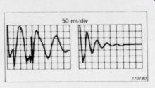
An immediate practical spinoff from this wisdom applies to audiophiles who want to correct what they hear as frequency domain irregularities in their listening rooms by using a graphic equalizer, when in fact the audible aberrations are caused by reflections, dif fractions and such, with con sequent peaks and suck-outs due to wave reinforcements and cancellations.
This crucial matter is il
Transient time response of two different tone arms with the same cartridge. 1978 B&K Inc.
lustrated by a witty example in the B & K paper mentioned above.
Consider a 3-way loudspeaker system playing pink noise...the tweeter is moved 1cm back, the level is increased a little bit-pink noise is still heard. 10 cm back-still pink noise. Now 10 kilometers back and the level is in creased a little bit (it is a powerful tweeter)-still pink noise. Finally, 100Km back-still pink noise (ignoring the high frequency attenuation of the air). Suddenly the power amplifiers are switched off. That is a transient. When that happens a change is audible, because the midrange and the bass stop, while the high frequencies go on for five more minutes-the time it takes the sound to travel the 100Km. In other words, when it is a steady state signal phase is not audible, but if it is a transient it is.
Let us assume that a symphony is played while the tweeter is still 100Km away. The first 5 minutes there will be no high frequencies.
After 5 minutes they will be there, but unfortunately they will correspond to the beginning of the sym phony and we are already in the second movement. After this it is clear that the influences of phase is audible-the question is only how much phase is audible? That is the kind of thinking that characterized the Heyser-Laedegaard sessions.
Allowing for occasional awkward pauses to fiddle with equipment ( “Why am | getting this indication? Something is not right here ”), the seminar was a nearly constant flow of useful applicable information.
Most of the time-disproportionately much, I felt-went to amplifiers and loudspeakers (the latter being Dick Heyser's particular preoccupation), but turntables, tonearms, cartridges, tape recorders and even tuners were examined as well in the attempt to find in formative measurements. (If the turntable is 'acoustically active’ and as a result the cartridge transduces acoustic energy in the air produced by the loudspeakers, sending back into the amplifier a substantially delayed “ghost ” of the program that may be only 20dB below what the cartridge gets off the record directly, what meaning is there in a -65dB rumble figure obtained in a silent laboratory measurement?) Even the “commercials ” when B & K's Southern California field office manager Joe Weatherstone stood up to re mind the group that B & K instrumentation was available to help perform the astonishing new measurements being demonstrated, were gracious and informative. And lunches and coffee breaks were included in the price.
The general distillations from the seminar:
1.We must take seriously the judgements of critical listeners who can distinguish repeatably among various components. “You can't be hearing a peak at 8,000-- I measured this thing and it's flat! ” is not an attitude that advances the state of the art.
2. We must be willing to discard meaningless data-in formation that does not correlate well with listening experience-whether the data came from a comfortable, traditional, easy measurement, or from our $10,000 microprocessor-real-time-analyzer that we just mortgaged the house to buy.
3. The ear/brain system is exceedingly sensitive to time (phase) relationships in signals that change with time (like music). How successfully a record/reproduce systems preserves these time relation ships is key to its naturalness.
4. Frequency and time are inseparably locked together as mathematical transforms of each other. They are alter native ways of observing the same phenomena. One cannot simultaneously make perfect measurements in both do mains. A sharp filter (sharp discontinuity in the frequency domain) causes ringing (a kind of “smear ” or indistinctness) in the time domain. A sharp pulse (distinct in the time do main) has a broad (indistinct) frequency spectrum.
5. The coffee at the airport Marina Hotel is terrible. At this writing I know of no plans to repeat the seminar regularly around the country, so I would urge readers who are interested to write to B & K Instruments Inc, 5111 W. 164th St., Cleveland, OH 44142 (and mention The Audio Amateur).
In a field in which break throughs come like snowflakes it is a pleasure to help spread news from a company that gets generally high marks for innovation, thoroughness and integrity. On June 3rd at the Consumer Electronics Show in Chicago, Dolby Laboratories held a news conference to unveil an ingenious offshoot of Dolby noise reduction called Dolby HX-for “headroom extender ”. Designed primarily for cassette recorders, it varies tape bias and record equalization depending on the instantaneous high-frequency con tent of the program material.
The practical effect is to gain a claimed 10dB additional headroom at 10kHz by reducing high-frequency tape saturation.
As the treble content of the source material increases, bias is reduced to permit higher signal levels to be recorded. At the same time, treble pre emphasis is reduced, which is permissible because the reduced bias results in greater high-frequency tape sensitivity.
The slight increase in hiss and nonlinear distortion that accompanies these alterations is successfully masked by the high-level, high-frequency pro gram content itself.
No playback processing or decoding of any kind is required, other than normal B-Dolby decoding. The gain in headroom is available with any kind of tape, including the new metal-particle tapes. The pro gram dependent cues for the HX system are simply tapped off the normal Dolby noise reduction encoding circuit. It is estimated that the added cost to the manufacturers of including HX will be about 30% above the cost of ordinary Dolby-B-type noise reduction.
As of the press announcement in Chicago, no cassette recorder manufacturers had yet been licensed for HX.
Dolby Laboratories expect to license HX at no extra fee beyond that for the noise reduction circuitry.
A demonstration for the press involved the copying on to a cassette (Maxwell UDXL II) of a pop record with some very sizzly tambourine. Without HX (but with Dolby-B and a moderate recording level), the tambourine's “jingles ” receded far into the background when the copy was composed with the source. With HX switched in, the source and the cassette copy were (to my ears) in distinguishable.
Readers who want more in formation may write to Dolby Laboratories, Inc., 731 San some St., San Francisco, CA 94111 (or 346 Clapham Rd., London SW9).
One of the most appealing approaches to designing a phase-coherent loudspeaker has been the ribbon transducers, cousin of the rib bon microphones that were once common in every radio station. (They are still prized by many recording engineers for their distinctive “warmth ” or “richness ”. In typical realizations, a thin (less than 1-mil) corrugated aluminum rib bon is suspended vertically between the poles of a very powerful magnet. The audio current is sent through the rib bon and causes it to vibrate, making sound. Because the horizontal dimension of the ribbon can easily be made as little as 1/2 inch wide (smaller than half wavelength at the top end of the audio frequency spectrum), the horizontal polar radiation pattern can be made quite uniform with frequency.
(The pattern of a symmetrical ribbon transducer is a figure-8, but it can be modified.) The ribbon's mass is extremely small, so it stores little energy and is easily accelerated to respond to steep wavefronts.
Its pulse response is among the best attainable from mechanical transducers.
Because of its small size and the fact that it is driven uniformly and simultaneously over its entire area it tends to exhibit little of the “breakup ” modes that are characteristic of conventional diaphragm radiators. The practical out come of all this ( “Where do | sign up? ”) is a loudspeaker of unusual transparency and highly precise imaging.
But the bad news: ribbons are disappointingly inefficient, because their small area does not couple well to the air. This gets worse as the frequency goes down, and cannot in practice be compensated for by increasing the ribbon's excursion or by mounting it on a baffle. A further engineering problem is that the electrical impedance of the ribbon is a small fraction of an ohm, man dating the use of a transformer to deliver sufficient current from a normal amplifier. (In one design, the ribbon side of the transformer is a single loop around the core, made of multiple layers of thin, wide copper foil.) The need for a very high magnetic field to get even barely acceptable efficiency has discouraged many workers, as has the fragility of the ribbon.
It does not require a great ...
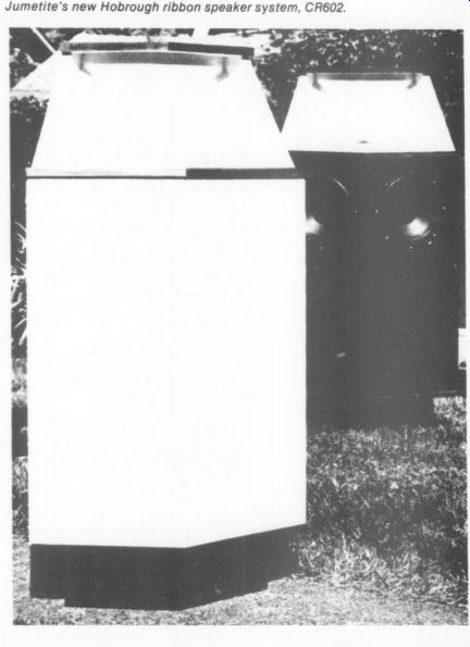
------------- Jumetite's new Hobrough ribbon speaker system, CR602.
... leap to conceive of coupling the ribbon radiator to the air with the aid of a horn. This has been done, yet still the range of the device was generally limited to about 2kHz and up.
This left an octave or two between the range comfortably handled by conventional drivers and the point at which the ribbon took over.
The June C.E.S. in Chicago saw the introduction of a production version of a very carefully thought out ribbon system in which the ribbon, with a unique horn design, produces frequencies from 600Hz up, while a pair of conventional 10 ” woofers in an acoustic-suspension-type enclosure take care of the bass. The Jumetite CR602 is a corner design that stands about 4 feet high. Its sensitivity is somewhat low by horn standards (91dB SPL on axis at 1 meter for 1 watt input), but then it isn't a Klipschorn , either. The ribbon design is unusual and incorporates several “layers ” of protection against damage from electrical overload. It measures 1/2 ” wide by 3 ” long by .000275 ” thick, and is embraced by a 64 0z. magnet. The horn is a “bent ” design with reflector, conceived so as to permit what the manufacturers calls “'exponential wave-front growth.
“It is not a conventional exponential horn, which (according to literature supplied by Jumetite) assumes, incorrectly, that the wave front is planar throughout the horn. ” The new design is claimed to eliminate the “honkiness' the designer finds to be characteristic of usual midrange horns.
A lot of attention seems to have been paid in the design to careful matching of woofers and ribbon, especially with regard to phase. To my ears, the design is successful. I listened to it for only about a half hour, in a small room with “artificial corners ”, but with Threshold electronics and a so-so Audio Technica cartridge, the sound was open and free of any obvious midrange colorations. Imaging was stable and reasonably precise.
The CR602 is expected to retail in the U.S. for $950 each in walnut and $890 in rubbed enamel. The manufacturer has available a respectable amount of lay-technical literature on the design of the CR602. Write Jumetite Laboratories, LTD., P.O. Box 35369, Vancouver, Canada V6M 4G5 (and of course mention The Audio Amateur).
Classic Circuitry
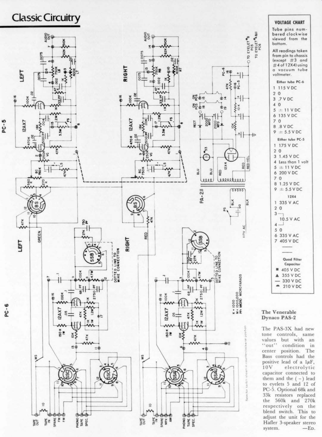
VOLTAGE CHART
Tube pins numbered clockwise viewed from the bottom.
PC6
All readings taken from pin to chassis (except #3 and
#4 of 12X4) using a vacuum tube voltmeter
YELET8 PCS TO EYELET
Either tube PC-6 1 115VYDBC 20 3 .7VBC 40 5 11 VDC 6 135V DC 70 8 8VDC 9 55VDC Either tube PC-5 175 V DC
0 1.45 V DC Less than 1 volt 11 VBC 200 VDC
0 1.25 VDC 5.5VDC 12X4 335 V AC
0 10.5V AC
0 335V AC 405 V DC Quad Filter Capacitor
405V DC
| A 355VDC
- 330VDC a 210VDC LL ARADS
The Venerable Dynaco PAS-2
The PAS-3X had new tone controls, same values but with an “out “ condition in center position. The Bass controls had the positive lead of a 1uF, 10V electrolytic capacitor connected to them and the ( -) lead to eyelets 5 and 12 of PC-5. Optional 68k and 33k resistors replaced the 560k and 270k respectively on the blend switch. This to adjust the unit for the Hafler 3-speaker stereo system. -ED.
Letters
CORRECTIONS
CONTRIBUTING EDITOR Jim Boak points out that K.S. Scriba is in error in his letter (744, 2/79, p. 49) regarding regulators. In negative three-terminal regulators the case is not at ground potential, but at ( -) input. Connect the case of a negative regulator to chassis without insulator and you will destroy it. So an insulator is still needed with a negative regulator. -ED.
WEBB UPDATE READER ROBERT MCELROY POINTS OUT a dimension error in three of the pieces for building B. J. Webb's Transmission Line Speaker. (744 1/75 pp. 3-9.) Subsequently (3/77, p. 49) two readers spotted the fact that piece #5 in the original cutting guide (Fig. 11a) should be 11% x 17.5 not 11.5 x 19.5 as shown. They are correct. The author later confirmed that the midrange slot begins 13 ” below the top of the cabinet. This means that the 13 ” dimension in the top right corner of Fig. 1 is incorrect. It should be 12.5. As a result of these two changes, three more pieces of baffle are incorrectly sized in Fig. IIa.
Numbers 8 & 9 should each be 10.5 x 11.5 and number 10 should be 9.25 x 11.5. We have carefully rechecked the diagrams again and believe all dimensions are now correct as amended.
LAMPTON-ZUKAUCKAS FOLLOWUP
DURING THE PAST SEVERAL MONTHS Don Zukauckas and I have received a number of useful suggestions from readers and friends concerning our LZ-1 preamplifier. We hope that our Kindly Editor will print some of these in his column.
Fred Gloeckler suggests that the alternate input switching circuit shown in Fig. la (TAA 1/79) can cause oscillation in a two-head tape recorder when it is in the “record ” mode with its gain advanced if the monitor switch selects that same recorder for playback.
Builders concerned with this situation ought to use a different switching circuit, such as one of the other three suggested in the article.
Perhaps one of 7A4A's readers or editors would be willing to review and discuss the various designs found in present-day preamps? Mr. Gloeckler also mentions that break-before-make rotary selector switches can be used. He is right. The use of “audio ” (shorting) make-before-break switches is an unnecessary holdover from vacuum tube days when the very high grid input impedance at the in-between positions (combined with frictional static electricity produced in switch contacts) would cause clicks when the switch was operated. Either type of switch can be used with lower input impedance circuits such as are found in the LZ-1.
Nelson Pass of Threshold Corporation has indicated his preference for simple effective discrete-transistor designs, and quotes some
very impressive performance figures for a three-transistor circuit. Perhaps he would be willing to share the details of his design with TAA readers? Reviewer David Vorhis detected an audible phono equalization error. David Hadaway later pointed out that the RIAA equalization components R; and C; were computed using the inverting-mode equations, but are actually used in the non-inverting mode for which the formulas' differ slightly. He is right; R;; and R,; ought to be 901.33k and C; and Cs ought to be 3528 picofarads. Nearby RETMA values are 909k, +1%, and 3300pF plus 220pF in parallel.
Advances in disk cutting practices (e.g. direct mastering and digital transcription) have improved both the signal levels and rumble levels of top-quality audiophile releases. Some experiments recently con ducted by Harry Pearson and Carl Marchisotto (The Absolute Sound, v. 4 #14, p. 184, 1979) show that with such records and a high output cartridge, there may be audible improvements associated with raising the preamp phono overload level to several hundred millivolts. With increased input capability, it also becomes practical to lower the infrasonic rumble filter's cutoff frequency by an octave from the original design, i.e. to 14Hz from 28Hz. I have redesigned the phono section to realize both improvements while retaining the use of the original board layout. The revision uses different parts in the feedback paths of the op amps. The parts list is given in Table 1. Parts with asterisks are new values. Also a new capacitor for each channel, 0.018uF, should be connected directly across the board's output terminal to ground, electrically in parallel with the 100k resistor.
The revised design has a 1kHz gain factor M = 27.300, i.e. 28.7dB at 1kHz. Its input overload level is raised to 330mV rms. This 11dB improvement in maximum signal level is accompanied by a reduction in noise level of 1dB, owing to the reduced value of Rs (which contributes appreciable thermal noise to the preamp). Thus the original dynamic range, about 106dB, is improved to become 118dB. The distortion, previously unmeasurable on my primitive equipment but thought to be somewhere around 0.003%, ought to be reduced further as a consequence of the reduced forward gain.
Preliminary listening tests have revealed little audible difference from the Hadaway revision except that the volume control now hovers near 12 o'clock rather than 9 o'clock.
We plan to conduct extensive listening tests on the revised design this summer, and welcome comments from interested readers.
For TAA readers who might wish to explore their own alternative phono preamp equalization circuits, I shall briefly sketch the corrected procedure used in the LZ-1 phono section. The first step is to adopt some numerical value, H, for the high frequency closed-loop gain to be obtained from the op amp. For good stability with the NE5534 we chose H =2, although with some other op amps H=1 is acceptable. Second, some numerical value M for the desired midband voltage gain factor must be adopted, based on the expected cartridge output and the op amp's maximum 9Vrms output. The phono input overload level will be 9000/M millivolts. The third step is to pick some value for Rs. Rs, together with M, sets the impedance level of the equalization circuit.
Values of Rs around a half kilohm are satisfactory. At this step, the RIAA parts are fixed:
Ris = Rs; x (H - 1) Ri = Rs x (9.123448M - 0.21739H) C; = 3180/R,; microfarads R; = Rs x (0.774632M - 0.78261H) Cs = 75/R; microfarads
The fourth step is to pick capacitor Cs to give the desired low frequency rumble cutoff.
Suppose you want a -3dB cutoff frequency ...
------------------
TABLE 1
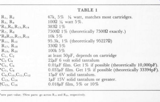
----------
... of F hertz. Then, for a critically-damped response (Q =0.707) choose Cs = 0.1125/(F x Rs) farads.
Fifth, complete the bridged-H rumble filter by choosing the remaining components Ra, Cs, and R;s. The critical requirement is to get the product of these three values to satisfy
Ro Ris Co = 0.225 x (R, +R; + Ris3)/F.
The sixth and final step is to equalize the ultrsonic response of the loop by loading the output terminal of the board with a shunt capacitor, whose value is Cis = 75.8 x H/(Ry; x M) microfarads This final step can probably be omitted if the desired time constant, 75.8 x H/M microseconds, is less than one or two microseconds.
MicHAEL LaMPTON Berkeley CA 94720
'See S.P. Lipshitz, 'On RIAA Equalization Networks' AES preprint 1424, 61st AES Conv. Nov. 1978.
A FORUM ON THE LIPSHITZ, VANDERKOOY, YOUNG LETTER
Preface
In Issue 2, 1979, p. 52, we published a letter from Stanley Lipshitz, John Vanderkooy, and Paul Young.
The authors of the letter called the Editor two days after the issue had finally gone to press, asking that the letter be withdrawn from publication. Since that was not possible, the Editor wrote to the authors after publication asking if they wished to formally withdraw the letter in this issue. They have not chosen to do so. We assume they wish the letter to stand and indeed, since it has been published, fairness to all concerned requires that it be answered. The letter has moved a number of contributors to respond, and a selection of them appears below, some edited for reasons of space limitations The issues raised by Messrs. Lipshitz, Vanderkooy, and Young are important ones about which more will be heard in these pages in future issues. I particularly appreciate the thoughtful reply, below, from the editor of International Audio Review, Peter Moncrieff. He reminds us that the rules of formal logic, a strict and demanding discipline, apply to interpretation of the results of all scientific experimentation and are quite as important as the rules for good science. Indeed logic is a branch of the sciences, which seems too seldom remembered by audio critics, experimenters, and other comparative listeners.
Although the authors of the original letter may have liked to alter their words and their report for publication, their letter is a valuable one in that it is the result of concerted efforts on their part to devise experimentation that is aimed at eliminating some of the uncertainties and unknowns that plague the search for good sound. We applaud their industry and willingness to act and interact with others.
Walt Jung replies:
I AM INTERESTED to hear that Messrs. Lipshitz, Vanderkooy, and Young have had sufficient interest in phono preamp audibility errors and our design to spend considerable time on a listening test comparison. I thank them for the nice words they have to say about our preamp. Unfortunately, I do not believe their listening test proves anything, much less supports sweeping generalization of their next to last paragraph, specifically:
The audible differences between them can be exactly accounted for by their linear differences-they explain the differences heard between phono preamps. I find, at the very least, this statement is an unwarranted one, and I am sure manufacturers of high reputation componentry may well bristle when they read it. But let me cite just two specific sources of audible preamp errors (out of many) which are not covered by this simple 'nutshell philosophy.’ One of these is audible masking or loss of apparent dynamic range and depth, due to dielectric problems in polar capacitors, such as aluminum and tantalum electrolytics.
Another is loss of separation, dynamic range and transient detail, due to power supply dynamic impedance problems. In the past few months, Dave White and I have made quite lengthy, painstaking investigations into these two general areas, studying its impact on the PAT-5/W J-1 modification. We find particular circuit is improved dramatically when polar coupling totally eliminated, and power supply impedance lowered. We cover the details of this revision in this issue, [see p. 24-ED] we therefore believe that unless such factors as these (and capacitors are others) are controlled sufficiently, any conclusions based on the above described experimental listening test, mean little or nothing.
In our experience the veiling effect of a number of polar capacitors can considerably mask the true clarity of a signal. Good ears using good equipment, with good source material, can hear one polar capacitor.
While I would not put words in his mouth I cannot help but wonder whether these factors were not what John Curl was referring to in his letter in AA 79 (p. 49). Our preliminary results in these two areas yield no measurable indication of the problem in terms of frequency response or conventional distortion tests. I therefore concur with John that we have not arrived at a place where we can predict accurately.
I have encouraged Lipshitz and company to redo their tests with these factors in mind, and furnished them with some sample “bad sounding ” caps.
They have done so and say they cannot detect the presence of these capacitors in a signal path in an A-B test. For the record, the particular units furnished were of the worst relative quality of a number of tantalum units on hand, all of which I can myself readily hear. The Lipshitz group have also meanwhile questioned my own listening test methodology, and suggested the effects being perceived may not be detected on a blind A-B. I am glad to report that their suggested tests have been made, from the capacitors-as do many other such tests, to and reveal bad sound subject participating listeners in addition to myself.
I hope Lipshitz, Vanderkooy, and Young soon begin conducting tests with appropriate equipment totally free of masking sources. Hopefully, they then will be able to hear the same kind of problems that we and many others hear and re-evaluate their conclusions.
In short, we believe their test setup lacks to hear what they should be hearing. And, I must add, we arc not talking about frequency response errors, I therefore strongly suggest that comments and conclusions such as are contained in the letter (and which inevitably will be interpreted by some the resolution necessary at least not static ones above as derogatory) are not warranted on the basis of such experiments. I feel that such conclusions are a grave dis-service to all of us, particularly the many dedicated people working very hard in these areas. It certainly would be simple if we could wrap up everything into a nice neat criterion, such as espoused above Such a viewpoint may suffice for mass market, lowest-common-denominator type stereo systems, but it is grossly inadequate for high performance ones.
Dave White replies:
FIRST, I TOTALLY agree with you that minute frequency response differences are audible on AB tests or long term listening. However, I disagree with your conclusions that once static frequency response and polarity are matched there are no audible differences. All you have proved with your tests is that you cannot hear audible differences. Do you accept as fact that if you cannot hear something that no one else can? May I suggest as an example the phonograph experiments in the late 20's and 30's where audiences could not tell the difference between a gramophone and live musicians? How about the AR live versus recorded demonstrations? I believe it is nearly impossible to audition components critically in an unfamiliar room and further, that listening acuity is a constant learning process. Because some people cannot hear a difference, 1s there none? Do you mean we have reached an audio nirvana in preamps by matching frequency response and phase? We are of the opinion that we are still a long way from the ultimate goal of high fidelity: the perfect reproduction of the audio signal. Just because there are imperfections in the recording chain is it futile to improve the reproduction chain further, as many engineers say? As we explain in our PAT 5/W -1 article in this issue, I can make a series of changes in a preamp that have no effect on static frequency response (a series of single frequency measurements) also, I have often wondered how frequency response would vary if multiple frequencies-as in IM tests used and very minimal effect on distortion yet the preamp sounds different listening to music. I am an engineer by training (although none of my degrees are in Electrical Engineering) and Walt and I are always striving to determine ways to repeatably measure the phenomenon we are hearing. We are both convinced that the ear is the final arbiter.
I disagree with two of your conclusions. First you conclude that there are no sonic differences between the two preamps because you cannot hear any. Does this prove no-one else could? Secondly, I doubt the validity of conclusion that having A-B'd two preamps that every time, everywhere, with any two preamps, if your parameters are met, every listener's results will always your duplicate yours. Gentlemen, obviously your results are as you stated them, but we don't agree with your conclusions.
THE BASICS OF REACHING SCIENTIFIC CONCLUSIONS
Dear Stan, Paul, and John,
WALT JUNG CALLED ME the other day, and we chatted about a number of things, especially concerning the surprising things the human ear can detect-even when we scientist/engineers are hard pressed for aural and electronic explanations (examples are: dif ferent capacitors, power supplies, wires and connectors, phase & amplitude variations, nonlinearities, etc.).
Walt, you three, and I, and about ten other people scattered around the world seem to have established an informal group for idea sharing. This group is a precious resource for us, and ultimately for the whole audio community. We are individuals who are imaginative and creative, yet rigorous in scientific method and thinking. On the whole, we're rational and therefore open minded in our thinking-not dogmatic, emotional, egocentric, or with a financial stake (product) to defend. We openly share information with each other on our latest research and ideas, long before they're ready for publication, which helps all of us by mental stimulation and cross fertilization, and makes progress move faster in audio. We've agreed to keep our confidential ideas and in formation private, and to give each other full public credit even for kernels of seminal ideas. It's all working beautifully so far.
I do see one cloud in this blue sky. No matter how rational and open minded we each try to be, it's always easier to change one's mind or position (when presented with counter-suggestions, -arguments, or -demonstrations by each other) if one has not already taken a strong public stance as an individual on some issue we're still exploring/discussing among ourselves. Something to do with that irrational human foible of saving face. A solution: extensive private cross correspondence before differences are aired and strong stances taken publicly. It is easier for differing humans to converge on the single rational scientific truth if they do so privately.
Private sharing has further benefits. For example, we can propose wild hunches or possibilities to one another for further investigation, secure in the feeling that our mutually esteemed colleagues will not think us fools. And we can call on each other for constructive criticism of our papers, before publication.
That's why I'm concerned about your re cent letter to the Audio Amateur for publication and also Walt's reply. I think it would be far better for you, for us as a group, and for future mutual research, if both letters were withdrawn from publication.
Normally I'm against censorship, even self censorship (I like to be very frank with my friends). But I think you'll agree that public grandstanding for its own sake, or public controversy for promotional purposes, are evils counterproductive to rational progress in science.
The publication of the present technical disagreement between you and Walt does two sorts of harm. First, it threatens the spirit of cooperative disagreement and constructive criticism that is an essential part of our group's future information sharing.
Second, your letter specifically will, I think, do needless discredit to you three, whose work many of us have come to admire and respect. Let's pretend I'm an editor blue penciling your paper before publication-or a friend/colleague offering to steer you clear of trouble.
Now, suppose I agreed with your experiment: that the two preamps sounded identical to me (after equalization). Suppose also that I agreed with your claimed conclusion: that all preamps would sound identical if their frequency response is set to be identical. Nevertheless, I see your letter as containing two severe sorts of errors (problem areas):
1. Very imprudent inductive generalizations from a too small sample population.
2. Negative universal generalizations that are illegitimate (even if they were inductively well supported as in (1), because they violate the M rule and the principle of agnosticism', and can't even be inductively inferred at all in interesting strength.
Problem area (1) actually is subdivided in to two errors, both repeated several times in your letter. You glibly slide from an evidence statement about two specific preamps into a generalization about all preamps. And likewise from an evidence statement about three (or so) listeners (and other specific links of your experiment/observation chain) into generalization about all listeners and audio chains. Your letter contains a number of in stances where you make these glib inductive leaps, and your generalization follow at all from the evidence. Occasionally the word “all ” is implicit in your syntax, making that conclusion a universal generalization; careful scrutiny of these will show how far removed from the evidence your inductive generalizations really are.
These repeated implicit leaps of inductive generalization do yourselves a disservice in the public eye. So also does the distance of the leap, from such a small sample population of preamps, associated chains, and observers-without the heavy argumentative justification necessary for such a leap. I does not
doubt, incidentally, that any such justification could be supplied, unless one makes the drastic assumption that all the many forms of nonlinearity in amplifiers 'sound' alike, and so are equally inaudible (when below a certain threshold, by very simplistic electrical measurement).
What about problem area (2)? It's even more basic. Your conclusion (stated several times in the letter) has the interesting form of a negative universal generalization with the peculiarity that it cannot be legitimately inferred at all from an empirical premise of a sample population (regardless how large), thanks (roughly speaking) to its law-like implications. In other words, even if you did expand your sample in problem area (1) to include, in a monster empirical experiment, all preamps permuted with all audio chains per muted with every listener alive-you still could not legitimately infer the conclusion you do.
Why? Consider as a pedagogical analogy the Royal Academy of Science's (early nineteenth century?) claim that 'Humans cannot travel faster than 18mph. That claim had 100% inductive empirical support at the time. What's interesting is that the universal generalization of that sentence can be interpreted several different ways, as different claims:
Evidence: (E) As a practical matter, no human has yet travelled faster than 18mph.
Claim: (a) As a practical matter, no human can (today) travel... (we lack the vehicular technology) (b) As a practical matter, no human can (ever) travel...(e.g. we lack the ability to ever in vent the vehicular technology).
(¢) As almost a matter of principle, for sound independent theoretical reasons, humans can never travel...(e.g. the laws of physics dictate that we will die (molecularly disintegrate)).
The RAS had inductive evidence (E) only to reasonably infer (a) as a generalization. Yet they intended to claim (c), a much stronger claim than (a). Not being fools, they surely realized they could not reach (c) inductively from (E), even with 100% population sample support. So they based their claim not on inductive inference as an empirical generalization, but instead on a foundation of a priori theoretical arguments (which, incidentally, were wrong-but that's of no consequence here-their rhetorical methodology was correct).
The claim you wish to make in your conclusion could be like (b) or (¢).
(b “) Audio chains will as a practical matter never get good enough for humans to aurally detect nonlinearities (in preamps) below x% measured by method Y.
(c¢') Humans are inherently (physiologically) incapable of ever hearing nonlinearities below....
Neither claim can be legitimately inductively inferred from empirical evidence, even a 100% sup porting population sample (like an E')from the monster experiment mentioned).
The strongest claim that could be legitimately inductively inferred from a 100% supporting population sample could be (a ') With today's audio chains (vehicular technology), no human today can hear nonlinearities below But I doubt you mean this. Claim (a) was not interesting for the RAS to make in its day, and (a') is not interesting for the design engineer today. As the state of the audio art advances, in products we receive and in the mods we make in our lab, we open new doors of aural resolving ability with our audio chain every week. An engineer doing high end product work who limits his design's performance goals to today's chains' resolution will more quickly wind up on the backwaters of yesterday (remember the c. 1924 experiment where a large group of people could hear no audible difference between an acoustic recording and a live orchestral).
Listeners sensitivities and sensibilities, which I consider part of the chain, also improve with training.
If the conclusions stated in your letter are intended to have the import of (b ”) or (¢'), then they cannot be legitimately reached by any process of inductive inference from your described experiments, no matter how extensive. You'd also have to supply independent theoretical arguments, as Mark Davis? has attempted for human hearing is physiological limits.
Note also that your experiments violate the M rule', and are therefore subject to victimization by blocked or masked illusions.
Since these illusions cannot be detected, the only scientifically valid methodology is to recognize where terra incognita lies and to be agnostic about any and all experimental results that seem to suggest no observable differences. I've discussed this 'principle of agnosticism' further in the P rule article and in chapter 2 of the SWB (postponed from International Audio Review issue 4 to issue 5).
The principle of agnosticism is not peculiar to listening evaluations in audio. It is not peculiar to the field of audio in general.
It applies to all observations for all scientifically correct endeavors in any field. It is this: Wherever you observe no difference, you may NOT infer that there IS no difference. Why? Briefly, every real object (device, system, phenomenon, etc.) is really different from every other in all parameters. If you can't detect a difference in some parameter, then you haven't really discovered something about the devices you're observing. Rather, you've just seen the bottom limit (like the residual) of your evaluative/observation techniques (for that parameter). All you're entitled to infer is that you don't know if there really is a difference in that parameter.
The test bench evaluator is a useful analogy here. If he observes some device under test (DUT) to have no detectable difference (or imperfection) from his test instruments' residual today, then all he claims is that simple empirical fact: I could detect no difference through my instruments today. He doesn't from that experimental observation make any inductive generalizations about what might be detected in that DUT's performance tomorrow, with different (better) test instruments. He doesn't because he can't know where below his residual the DUT's performance lies, or how good test instruments might become tomorrow. He certainly doesn't claim that it is and always will be irrelevant to design DUTs any better than today's test instrument residual just happens to be.
As 1 said, the two problem areas I've just discussed are, I think, weaknesses in your letter, even if I were to agree with both your experiments and your conclusions. It hap pens incidentally that I don't, but in this area there's plenty of room for constructive and Apt preamp may have sufficient nonlinearities themselves to be masking the nonlinear differences between the two preamps (M rule violation - masked illusion). Note incidentally that, technically, you're not actually eliminating all linear differences in your experiment, as you claim; in equalizing for amplitude you’re disrupting phase with the octave equalizer (perhaps in significantly pragmatically, but your technical description of your experiment needs cleaning up on this point). (John Curl gets credit for bringing this to my attention.) That's concerning your specific experiments.
As to your conclusions, I'll merely say that I regularly evaluate nonlinearities in DUTs of all sorts-from preamps to capacitors to audio cables. Not only do I hear nonlinearities, but I have about 20 rough sonic parameters to describe the various audible qualities of different kinds of nonlinearities. I can know with many DUT (not all) that the errors I'm hearing com pared with a straight wire are nonlinearities (not linear errors) because with these DUTs (not all) I can separately measure the nonlinear and linear errors, and with some DUT: I can confirm that its linear behavior is almost no different from the straight wire.
If pressed, I can confirm this linear 'tracking' down to a deviation tolerance of 400 pico-bels (.000000004dB) or so. Obviously the remaining audible differences are probably nonlinearities-and they sound like it (grundge, blur, etc.).
I agree with prior statements made by people among preamps (and speakers and cartridges), whether these effects sound as if they are linear or nonlinear, are primarily caused by linear differences. But that's a long way from saying that only the linear differences are audible. And note that it, in its carefully lengthy wording, is not even the same as simply saying that people primarily hear linear differences among preamps (that simple statement could be ambiguously taken to mean that people hear these dif ferences, whatever their cause, primarily as linear differences effects, which they perhaps don't-else why such confusion as in this forum (see the cause/effect conflation discussion in IAR 3)).
J. PETER MONCRIEFF Editor/Publisher International Audio Review 2449 Dwight Way, Berkeley CA 94704
REFERENCES
1. International Audio Review, Nos. 3, 4, and 5 Rule ”, “The M Rule', “IAR's SWB ”
2. Mark Davis, 'The BAS Speaker' and elsewhere
--------------------------
The PARALLELING, MAGNETICS & IN READING
THE LATEST LETTER by Lipshitz, et al, I could not help but be surprised by the far reaching conclusions made by the authors regarding listening differences between preamps. While I concur that RIAA equalization differences can be very important, especially with regard to AB listening tests, the authors have made technical oversights which could mask any potential differences between the preamps under comparison.
The first oversight was paralleling the in puts of the two preamps with a high inductance (Shure) cartridge without consideration of the effect of inaccurate loading on phono cartridge frequency response. Because the two phono inputs were in parallel, only one half the standard resistance loading was seen by the cartridge. This over-damps the electrical resonance and reduces the high frequency response approximately 6dB from its usual value at 15kHz. I, for one, would find it difficult to make subjective comparisons between components without extended high frequency response present in the test set-up.
The authors should be two aware, since I assume that they have a copy of my paper in their possession! that the Shure phono cartridge is one of the most limited of present day phono cartridges in ultrasonic band width. A more appropriate choice when testing for potential TIM would be either a Sonus or a Grado phono cartridge (if one wishes to remain restricted to moving magnet types exclusively). A more valid at tempt to detect “worst case ” TIM and other high frequency related distortions would use a moving coil cartridge such as the Ortofon MC-30, which has a spectral bandwidth of approximately 200kHz, can generate pulses (when mistracking) with peak periods of 5-u-s, or less and with peak amplitudes approaching maximum output capability of the cartridge.
A third factor is the potential masking of any changes of input impedance with frequency in either of the two preamps (ref. Holman) and any distortion generated by non-linear input capacitance (ref. Yamaha).
Having the two phono inputs always in parallel with a high impedance cartridge superimposes the same distortion on both preamps and any potential differences between the two will be masked. These factors relate only to the input stage. I will pass over other oversights at this time, because I believe my point has been made.
A double blind listening test, while removing a subjective bias toward hearing differences that may not truly exist, unfortunately does nothing to remove bias toward NOT hearing any differences that may actually exist in equipment. Indeed a double blind testing situation could intimidate a listener not to take a stance, since one could be embarrassed, if misled momentarily by a change in the quality of timbre of the musical source, to make what would seem to be a random decision. It seems we must invest a certain amount of faith in the objective integrity of the listener in any case.
In conclusion, while I applaud any efforts to remove some of the inconsistencies in the listening tests, I believe a more technically accurate approach must be taken to correctly evaluate differences between equipment, that one must be willing to accept that others in the industry are also attempting to clarify audio design criteria, and seek a better understanding of the listening process.
Ultimately, I hope we can work together to advance audio design beyond the mysticism and sales hype that is present in so many in stances, without irresponsibly disparaging much of the serious research aimed at improving the sonic qualities of existing audio equipment.
J Curl Berkeley, CA 94705
J. Curl, “Omitted Factors in Audio Circuit Design ” IEEE Conference on Acoustics, Speech & Signal Processing, Tulsa, OK, April 1978
5534 IS TOPS ANYONE BUILDING the Mark One preamp (TAA 1/79, p. 5) will be pleased with the value offered in this unit. Last year I design ed and built a phono preamp using the NE5534AN and was amazed with the results. Recently a friend and I auditioned several op amps and found the NE5534AN to be the best of the lot, with the BiFets from National and T.I. placing a close second.
Surprisingly, the LM318 sounded poorly when compared to the others, even though it “specs ” well.
A simple tone control bypass switch should have included in the Mark One design. All the preamps I have auditioned sounded better with the tone controls bypassed.
JouN S. PHiLLIPs Raleigh, NC
ADDING CAPACITORS TO MK III
I THOROUGHLY ENJOYED Jim Boak's article (TAA 1/78, p. 32) on the Dynaco Mark III and intend to the indicated modifications.
It seems to me that capacitors in a power supply serve two purposes: to reduce ripple and to store energy. Your regulator circuit takes care of the ripple but the total capacitance is 14.17uF. This will not allow a great energy reserve.
In my experience amps with large energy storage capability are better able to reproduce the transients in music. What would be your reaction to adding the circuit in Fig. I to the power supply at one of points A, B, or C: perform in your Fig. 3:
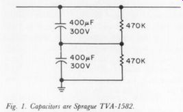
Fig. 1. Capacitors are Sprague TVA-158
I am not sure whether the resistors are really necessary since the caps have equal voltages. If they are needed, then I would guess a reasonable size to be 0.5M-ohm, 0.5W, 5%. These extra items could be tucked away under the output transformers. If the above arrangement is installed at point C then would mC4 be necessary? It seems it would be a good idea to let the 6550's heat up thoroughly before signal is applied to them. To accomplish this one could install an Amperite 5N030 in the octal socket previously used by the 5AR4. The and TR2 would have to go elsewhere.
5N030 would be transformer diodes The powered by the 5V leads which were tucked away and only the B + going to the 6AN8 would be switched by this delay tube. Or one could wire the transformer to the AC bypassing the on/off switch, and switch the B + just before point A. Then the filaments would be heated as long as the amp was plugged in.
And finally, would the performance of the bias circuit be improved by replacing the Dyna 50uF 75V capacitor with one of the higher value, say 500uF 75V?
ROBERT S. SMITH
Oxford Audio Consultants Oxford, OH 45056
Jim Boak replies:
You are correct about the limited energy storage of the modification circuit; the circuit you propose is a good choice. I suggest using it before the choke only, as the resistance of the regulator to short circuits on the output depends on the limited energy storage of the capacitance seen after the choke. The choke would keep large currents (large peak) from destroying TR2 by secondary breakdown.
As the current through the choke increases, the falling output voltage will turn TRZ on hard, improving its current capability.
Likewise, any significant capacitance at point C increases the chance of secondary breakdown at turn on, although the zener mD3 reduces this possibility.
Several readers have suggested using a delay relay, and I agree it is an excellent idea. In issue #4/78 p. 54, I proposed using an Amperite 115N030T, but I think your suggestion of a 5N030, is much better, and I suggest that your solution to this problem be considered by amateurs along with (or in place of) my own.
The bias supply certainly needs some help, but the real problem is the rectifier and AC The use of a big capacitor would probably be a good stopgap, and can't help but improve matters. I didn't find a really satisfactory solution to this part of the circuit, short of replacing the AC supply and using a full wave rectifier, which I thought was a little excessive.
As you suggest, good capacitors will have similar leakage currents, and the voltages will tend to balance. As the capacitors age, these leakage currents will change, however; and the one which ages fastest will have less The eventual result is that the better of the two sees an ex voltage across it as a result excessive voltage, overheats, and is damaged. I think 470K is a good value; 1M is also OK (for voltage dividers).
MRM BYPASSED, ANYONE?
I'D LIKE TO GET IN TOUCH with other TAA readers who have had experience with by passing the phono cartridge preamplifier section of the Garrard MRM-101 (Music Recovery Module) so it can be used to pro cess records from other sources. Plessey Consumer Products (Garrard) in Plainview, NY, do not recommend this modification, but I consider it such a shame to limit the MRM use to processing my own records when my favorite FM station has many less-than perfect records.
Does anyone have pictorial and schematic diagrams of the MRM-101's circuits?
ANDREW D. KELLER
1455 Twin Sisters Drive Longmont, CO 80501
----
Also see:
Test Report: Listening tests of the PAT-5/WJ-1A, by Laurence L. Greenhill, M.D.