A Vacuum Tube, Variable Frequency Crossover--Butterworth, 18dB per octave and with movable knees.
MY URGE TO CONVERT my audio system to bi-amplification came about when I acquired a second Dyna ST-70 to add to my existing ST-70/PAS-3X Dyna combination. The only obstacle was selecting an appropriate active crossover. Since my present system is all tube, I wanted to build the crossover using the same technology. Heathkit, Marantz, and Audio Research designs are available (see TAA 3/75 and 4/75); in each of these, however, the crossover point is switch-selected and | wanted a continuously variable crossover point. 1 also wanted the system to roll off at 18dB/octave beyond the crossover frequency, which none of the older tube designs does. My solution was to design my own crossover and the system describe in this article 1s the result. The crossover frequency is variable over a 10:1 range with switch-selectable ranges of 20Hz 200Hz, 200Hz-2kHz, and 2kHz 20kHz. The system's gain is nearly unity.
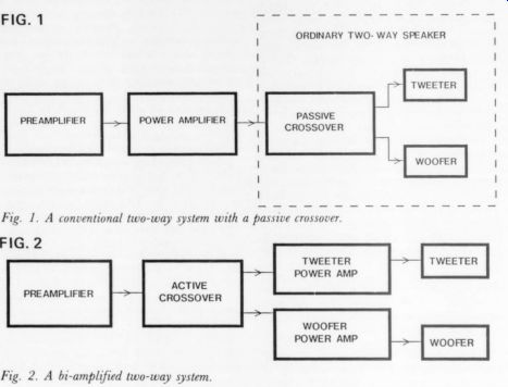
Fig. 1. A conventional two-way system with a passive crossover.
Fig. 2. A bi-amplified two-way system.
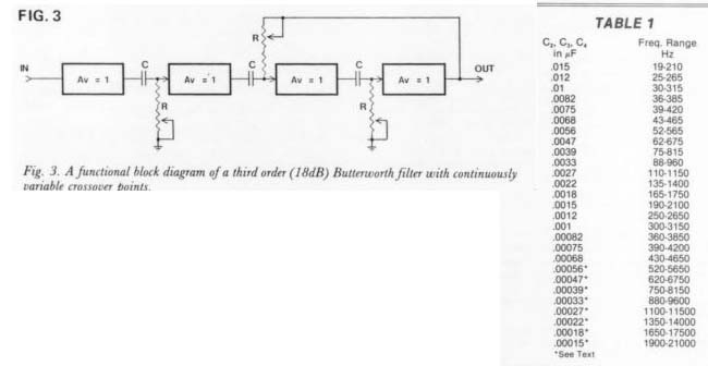
Fig. 3. A functional block diagram of a third order (18dB) Butterworth filter with continuously variable crossover points.
TABLE 1
WHY BI-AMP?
Bi-amplification is a popular scheme for improving sound reproduction. Figs. 1 and 2 compare a conventional two-way system with a bi-amplified one. Bi-amping eliminates the passive crossovers in the speaker unit and uses instead an active crossover between pre-amp and separate woofer and tweeter power amplifiers. Such a system's benefits are lower distortion, better crossover characteristics, and more apparent power. (For a good discussion, see “Bi-Amplification-Power vs. Pro gram Material vs. Crossover Frequency, ” by J.M. Lovda and S. Muchow, Audio, Sept. 1975.)
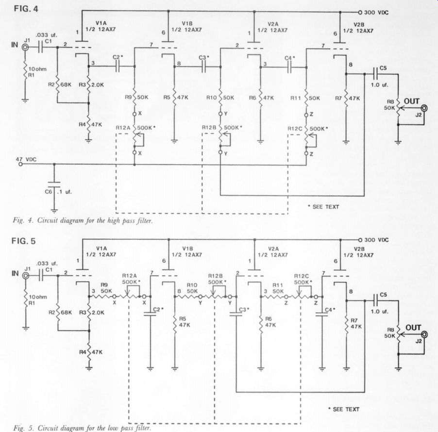
Fig. 4. Circuit diagram for the high pass filter.
Fig. 5. Circuit diagram for the low pass filter.
------------
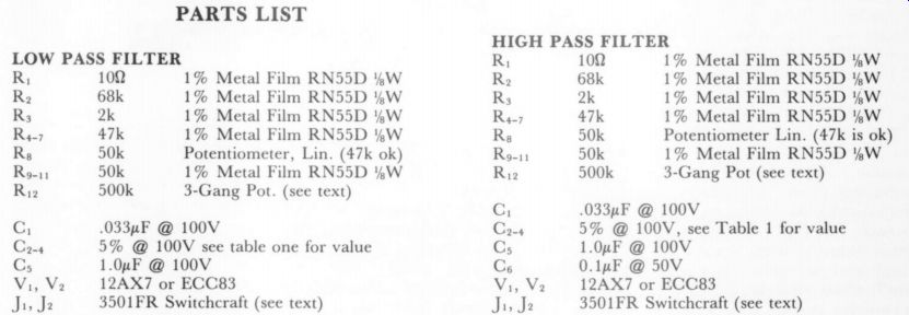
PARTS LIST
HIGH PASS FILTER
----------------
A BIT ABOUT THE DESIGN
According to National Semiconductor's The Audio Handbook, the optimum transfer function for bi amplification is a third order Butter worth response, so this is what I set out to build. Fig. 3 is a functional block diagram showing how a third order Butterworth filter with continuously variable crossover points could be built. A high-pass filter is shown; exchanging the positions of R's and C's would yield a low-pass filter.
Each amplifier block has unity gain and may be built using a single triode cathode follower configuration. Cathode followers have high input impedance and low output impedance, making them ideal for use in this filter; they also have low distortion and can handle large signal levels. Adding the cathode followers and appropriate biasing circuitry to the diagram of Fig. 3 yields Fig. 4 the actual schematic of the high-pass filter. Fig. 5 shows the low-pass filter. Calculate crossover frequency as follows:
F. = 1/(6.283 Xx R x C)where C = C; = C; =
Cs and R = Rg + Riz. Rio » Riz = Rii + Ry.
Input impedance is 1 M-OHM for a single filter section and 500k for two sections in parallel, making it compatible with both tube and transistor preamps.
You can use any power amplifier with an input impedance of 10k or greater. For power amps in the 10k-50k range, increase Cs to 3.0uF @ 100V. Tubes used are 12AX7's and are not critical in this design; use any good quality brand you can get, and those tired ones replaced in your PAS will do just fine in this application.
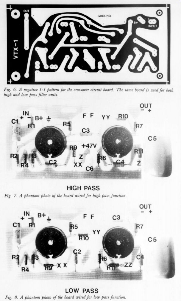
Fig. 6. A negative 1:1 pattern for the crossover circuit board. The
same board is used for both high and low pass filter units.
Fig. 7. A phantom photo of the board wired for high pass function
Fig. 8. A phantom photo of the board wired for low pass function
BUILDING THE BEAST
Since no two people build a project the same way, I will not attempt to describe mechanical layout. Use a metal enclosure and good layout techniques and you should have no problems. The crossover as described here is a two-way, two channel system and uses a total of four filters, two high-pass and two low pass. You could easily expand to a three-way system (see Fig. 12 ) or a quad system, although one could go broke buying power amplifiers. A center channel bass configuration is also possible (see Fig. 13). One etch ed circuit board pattern is used for both high and low-pass filters (Fig. 6); you'll need four boards for a stereo two-way system. Figs. 7 and & show parts placement for both filters. Note that not all donut pads are used all the time.
If you want only one range of crossover frequency, you can mount C..4 directly on the board as shown.
For more than one range, run twisted pairs off the board to a rotary switch, which should have three poles and one position for each range desired. It should also be of the make-before-break type to reduce popping. Table 1 gives values of Cy-4 for different frequency ranges.
Twisted pairs run off the board to Rjs.-.. Connect Ris, to points X, Riz to ints Y, and Rz, to points Z. Note that points X, Y, ...
also
-----------------
PERFORMANCE
Noise:
(Either high or low-pass) is 300uV p-t-p or 79dB below 1V RMS. (input shorted).
Total Harmonic Distortion:
(either board: low pass at f. = 20kHz, high-pass f. set to 20Hz.) 1% @ 1V RMS = Residual.
2% @ 5V RMS (Residual =0.17).
Measured at 1kHz, null type analyzer.
Frequency Response: i Low pass +0 -3dB, 5Hz to f.
High pass +0 -3dB, f. to be yond 1MHz. (My signal generator only goes to 1 MHz.)
-------------------------------
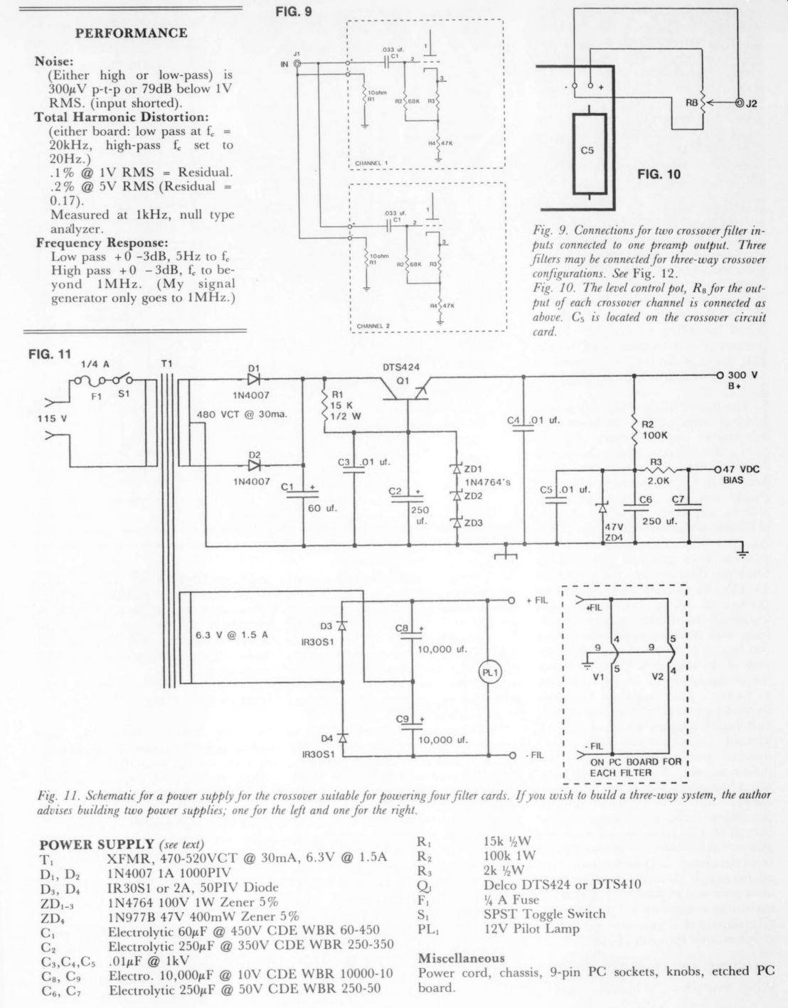
Fig. 9. Connections for two crossover filter in puts connected to one preamp output. Three filters may be connected for three-way crossover configurations. See fig. 12.
Fig. 10. The level control pot, Rg for the out put of each crossover channel is connected as above. Cs is located on the crossover circuit card.
Fig. 11. Schematic for a power supply for the crossover suitable for powering four filter cards. If you wish to build a three-way system, the author advises building two power supplies; one for the left and one for the right
----------------
POWER SUPPLY
Miscellaneous: Power cord, chassis, 9-pin PC sockets, knobs, etched PC board
-------------------------------
... and Z are in different places on high and low-pass boards. R,; is a three gang counterclockwise modified logarithmic taper control (Allen Bradley 70E4N048P504B or Bourns 82A3A-B24-F23/F23/F23). A linear control will also work but the frequency points will be squeezed over to one end of the rotation.
Use twisted pairs for the input and output leads. Isolate input and out put jacks J, and J; from the chassis using nylon or fiber shoulder washers or rubber grommets. I used Switchcraft 3501FR's which mount in 3/8 ” ID shoulder washers. If you wire two filter inputs in parallel (as they would be in most systems), run twisted pairs from each board to the common input jack, as shown in Fig. 9. Rg, the level control, should be wired according to Fig. 10 with its ground return connected to the circuit board at the output (-) point. A separate wire runs from output (-) to Ja.
The power supply (Fig. 11) is easily hand-wired or you can build it on an etched circuit board. Fig. 14 shows the foil pattern for the power supply; Fig. 15 gives the parts layout. In the foil pattern, k's mark diode cathodes, +'s mark electrolytic capacitor polarities. Variations on the power supply are possible; the only restrictions are (1) it provide approximately 300VDC @ 6mA per filter section, (2) it provide 12-14VDC floated with respect to ground @ 0.3A per filter section, (3) it provide an absolutely pure 47 volt bias. Any noise or ripple present on the bias will be present at the out puts of the high-pass filters! Connect the filament supply to points F with a twisted pair and use another twisted pair to connect B + and circuit board ground (marked with a ground symbol on the parts placement diagrams, Figs. 7 and 8) to the power supply. The chassis is connected to ground only at the power supply and the circuit boards themselves (except the power supply board) should be mounted with insulated standoffs to isolate them from the chassis and each other. The power supply shown is good for four filter sections. If you want to build a three-way system with eight filters, I recommend that you use two power supplies, one for each channel.
TESTING AND CALIBRATION
When everything is assembled and all wiring double-checked, apply power and check voltages against the values in Table 2. If cathode voltages are not within specifications, check R;_;. Also check that the bias supply is 47VDC +5%. If the voltages are right, you can now calibrate the unit. This requires a sine-wave generator and either an ac voltmeter or an oscilloscope.
The crossover frequency (f.) is that at which the output falls to 0.707 (-3dB) times the midband output.
Recheck midband gain for each range as it varies slightly from low ranges to high ranges, especially in the high-pass filter. For values of Cz-4 smaller than 600pF the low-pass filter will have errors in the frequency calibration increasing in severity as Cs-4 decreases: for C2-4 = 150pF the error is almost 20 percent. This is caused by stray circuit capacitance and can be corrected by subtracting about 30pF from the value given in Table 1; you must find the exact amount to subtract by trial and error. If you really want precision, subtract 40pF or so and use three 20pF trimmers in parallel with C 2-4.
You can adjust these (in unison) to exactly match the high range to the lower ranges so you can use one scale with a multiplying factor for each range.
TRYING IT OUT
Having built, checked, and calibrated your crossover, hook it in to your system according to Fig. 2.
Wire woofer and tweeter to their respective power amplifiers with opposite polarity (out of phase).
Bypassing the passive crossovers in most commercial speaker systems should be fairly easy, but be sure you know what you're doing and be gentle with that screwdriver! I highly recommend fusing the individual drivers.
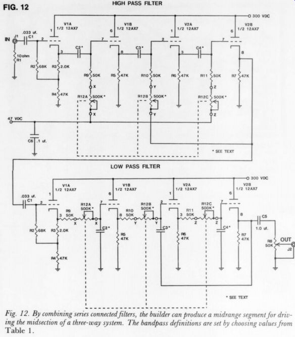
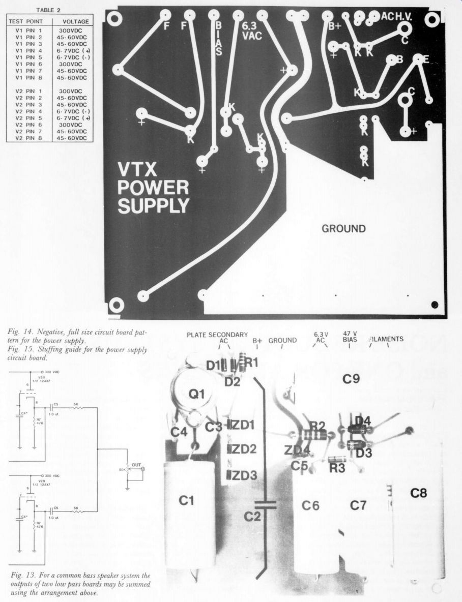
Fig. 12. By combining series connected filters, the builder can produce a midrange segment for driving the midsection of a three-way system. The bandpass definitions are set by choosing values from Table 1.
Fig. 13. For a common bass speaker system the outputs of two low pass boards may be summed using the arrangement above.
Fig. 14. Negative, full size circuit board pat tern for the power supply.
Fig. 15. Stuffing guide for the power supply circuit board.
Turn everything on, find your best recording (direct-to-disc will astound you), and enjoy the increased detail and crystal-clear midrange that a biamplified system delivers.
by Brian Waldron
----
Also see:
Noise Reduction Systems and One for Amateurs, by Reg Williamson
Test Report: Listening tests of the PAT-5/WJ-1A, by Laurence L. Greenhill, M.D.
The PAT-5/WJ-1A: A PAT-5 WJ-1, update by Walt Jung and Dave White