Noise Reduction Systems and One for Amateurs
EVERY AUDIO ENGINEER accepts a fundamental fact-that each part in a transmission chain can degrade the quality of the signal to some degree, especially if it contains active components such as amplifying stages or a time delaying element such as a recorder, using either the magnetic tape medium or the mechanical one of a conventional disc.
The effects of such defects that can arise may be minimized in the design process; others, such as amplitude non-linearities may be corrected later by the techniques of equalization-within limits, of course.
But where the transmission system adds unwanted noise to the signal, there is very little that can be done by post-correction.
The only currently available guarantee against the corruption of an audio signal whilst passing through a 'noisy' transmission system is to turn it at the outset into a form that makes it virtually immune to degradation in this way, i.e. from its conventional analog state into digital form. A digitally encoded signal can be recorded, sent theoretically infinite distances over transmission links of various kinds; yet on conversion back to analog form, it will still be virtually a carbon copy of what went into the analog to digital encoder.(1) Ideal, one might say-so what's the problem? Well, in the real world, one gets nothing for free and all digital trans mission systems demand very wide bandwidths, far wider in relation to the requirements of a comparable analog system. So for a long time to come, we will be living with conventional analog systems; and it is understandable why, over the past decade and more, we have seen the introduction of techniques for use tape recording and to a extent, in processing audio signals for transmission over other potentially noisy media. I have used quotation marks around 'noise reduction' because it is semantically suspect. Noise inhibition is rather more accurate, but to avoid confusion, we will stick with the more commonly used term.
'noise reduction' primarily in lesser During the course of this article, I shall touch briefly upon the basic problems around the techniques of inhibiting the introduction of unwanted noise into a transmitted or recorded audio signal; mention the main, and largely successful systems that have been introduced; and finally describe a simple version that the interested reader will be able to construct for use in a home recording setup.
WHAT TO DO WITH NOISE?
To begin by examining the problem in some detail, let us assume for example, that we wish to record a live orchestra playing a late romantic work, such as a Mahler symphony. The actual dynamic range of sound may well vary in any given instant from a ppp passage on a solo violin to a full orchestral tutti of fff dimensions.
Measuring this dynamic difference, we would find it spans well over 80dB.
Consider now, even a top grade reel-to reel tape recorder. The tape medium itself has an inherent noise base so our quietest passage has to be recorded at a sensible flux level above this in order to avoid the noise-usually in the form of a hiss- being a distracting aural intrusion. On the other hand, the magnetic medium has also a 'ceiling'-a maximum flux level which if the recorded signal begins to approach it in magnitude, occurs saturation and distortion to the recorded waveform results. This point is usually defined and the user avoids exceeding it by means of information from a record level orchestra in full cry. The problem becomes more acute with the reduction in tape track widths and a lowering of the linear tape speed.
We all know what happens, of course; when the recording is actually made, some means of manually compressing the dynamic range is adopted and a skilled balance engineer can make this action quite unobtrusive. But nevertheless, the dynamics are compressed and it is interesting to observe en passant that many of our hi-fi commentators will seize upon and harass to death this or that aberration in an audio reproduction system, whether real or imaginary; yet will ignore the all important deficiency of dynamic range which has never been wholly solved since the invention of the phonograph.
THE DOLBY ANSWER
The first noise reduction system to both enjoy commercial acceptance and well deserved success is that due to Dr. Ray Dolby, with his “A” system for use in tape mastering at professional levels. The first phonograph records to appear in which it had been used by one of the British companies was in 1967, a solo piano disc by Wilhelm Backhaus playing four Mozart sonatas on Decca SXL6301.
Superbly played and recorded-but the tape hiss is much more obvious on one side than on the other, the explanation being that the recording sessions extended over the period in which Dolby A units were being brought into use.
How the Dolby A system works has been covered adequately elsewhere(2) but suffice to say it is a very sophisticated dynamic equalizing system. It operates over four bands in the frequency spectrum. In the recording process, increasing amounts of pre-emphasis are applied to the signal in these bands as the level falls near the noise base. The equalization is at a minimum when the tape saturation level is approached and this is defined as a reference or Dolby level.
It follows that as Dolby A is a complementary system, that is, it requires an exact complementary decode function on replay, then record / replay level parity is essential otherwise tracking errors will become unacceptable very quickly because of the non-linearity of the dynamic equalizing characteristic. It is very effective, hence its almost universal adoption for use throughout the recording industry. The increased availability of between 10 and 15dBs before the noise becomes obtrusive has made the need for extensive manual compression during recording not quite so essential over a wide range of program material.
The much simpler single band Dolby B system followed soon afterwards and one could rightly argue, played a dominant role in establishing the Philips Compact Cassette with its narrow tracks and low speed, as a viable high quality program source in the home. Dolby B's use and effectiveness is largely confined to the domestic tape medium at speeds of 19cm / sec (7 1/2ips) and below. Dolby A, ...
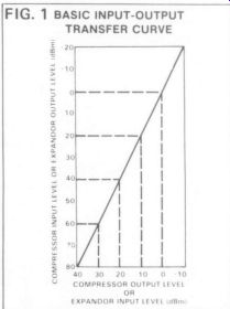
FIG. 1 BASIC INPUT-OUTPUT TRANSFER CURVE
... on the other hand, may be used for other transmission media to advantage and indeed is, by many broadcasting and communications bodies throughout the world.
Nevertheless, it would be wrong to conclude that there are no possible alternatives to the Dolby systems. The very need for a reference level, established some years ago when tape coatings were rather less sensitive than they are now, can produce difficulties in the studio when the recording engineer wishes to take advantage of the increased headroom of a modern tape formulation, where saturation effects may begin well above the original reference level. It could even be argued, that with modern tape formulations--and the improvements show no sign of coming to a halt-the cost and complication of an analog noise reduction system is becoming increasingly un necessary.
Certainly, improvements in tape coatings designed for the cassette market have made possible improvements in the S/N ratio and dynamic range, even without Dolby B, that would have been considered futuristic ten years ago.
However, these improvements, welcome though they are will still only partially solve the problem of recording the full dynamic range of some program material;
so we may safely assume that noise reduction systems will still be desirable for some time to come.
THE dbX SYSTEM
It is worthwhile examining the alter natives, mainly as an introduction to the simple system to be described for the home constructor. Many have been suggested and all fall into that category of signal processing device known as a Compandor:
a contraction of Compressor and Expandor. Only one seems to have survived the rigors of intense competition and is almost as old as the Dolby systems. This is due to David Blackmer, and is known as “dbX ” (the use of the lower case is part of the trade name).
This is, again, a complementary system and employs the companding technique.
The original audio signal is fed into a compressor which continuously monitors its amplitude and energy. From this is derived a control current, which is applied to a variable gain cell. This has the effect of altering the signal rate of change at a 2:1 ratio along a square-law or 'deci-linear' transfer characteristic. So for example, a change in the dynamic level of 6dB will be reduced to 3dB and a full dynamic swing of 100dB down to 50dB; well within the capability of a tape recorder. On replay, the reverse takes place and the compressed signal undergoes a 1:2 change in the expanding process.
(Fig. 1,2) Rather a generalization, but a more detailed explanation is available elsewhere(3).
It has two advantages that apply to any companding system using the deci-linear transfer characteristic-there is no need for a reference level and the compression and expansion rate is uniform above and below any unity gain point; and the effective lowering of the noise base is also uniform throughout the frequency spectrum. Whilst the dbX system was developed primarily for tape recording and as such, allows a considerable-one might say, more than enough-increase in the signal-to-noise ratio of the medium, it can be used with other transmission media with equal success.
It is also possible to make conventional disc records that are dbX encoded, with the virtual elimination of surface noise.
This writer has heard some test pressings of the Mahler 3rd Symphony, the sound of which can only be described as shattering.
To hear this mighty work with its dynamics virtually unrestricted from a recording is some experience.
Before anyone decides that companding is the best invention since sliced bread, let me make it quite clear-there are snags, sometimes quite substantial ones. The first is inherent in the companding process and is a defect known as 'breathing.' Even a compressed signal cannot be fed through a noisy system without some degradation.
Additional techniques are necessary to keep it within acceptable limits. If significant noise exists in the interface region between compression and expansion, it is possible for the signal to modulate this noise: and depending upon where it is in the spectrum, will determine its character and how obtrusive it is.
The most common is tape hiss and the resulting effect occurs when, for example, a soprano sings without accompaniment in a dead acoustic. Each note she sings will have a fuzzy aura added to it by the hiss.
This will happen with any isolated musical sound without the benefit of a lively acoustic or accompaniment to mask it.
Needless to say, solo piano or solo singer are two of the most effective tests for any compandor.
In the dbX system, part of the technique to reduce the defect is one of pre- and de-emphasis to the compressed and expanded signal. This reduces 'breathing' due to modulation of the hiss by the signal to an acceptable level. Other defects inherent in the companding process can be minimized by the design techniques, particularly that of 'pumping' which occurs when the compression and expansion dynamic envelopes do not match; in other words, one can hear it working.
Other problems are also inherent in the companding process. For example, amplitude non-linearities in the replay mode will also be exaggerated by a factor of two;
so what one may feel is an acceptable amplitude spread of plus and minus 2dB over the audible range will become degraded to an unacceptable plus and minus 4dB: an 8dB deviation. But it is when one measures the amplitude spread of even quite costly pickup cartridges, that one must be ready to appreciate that reproducing dbX encoded discs has still a few attendant problems to be sorted out.
But when they are, then believe me, the results are well worth the effort.
BUILDING YOUR OWN
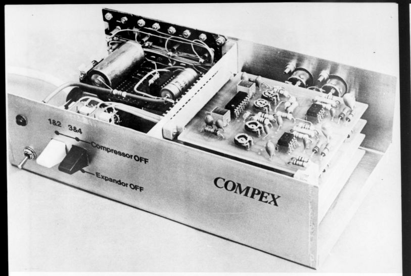
Now we can turn to the constructional project. This is also a compandor which works on similar lines to the dbX system, although it must be emphasized strongly, it is neither comparable in the quality of performance nor is it in the slightest degree compatible with it. dbX is a highly sophisticated circuit of some complexity and elegance of design and it does un fortunately, carry a price tag to match at the present time.
Our compandor, on the other hand, will perform satisfactorily to most standards demanded by the amateur and will cost the constructor a fraction of the price.
Fig. 1.
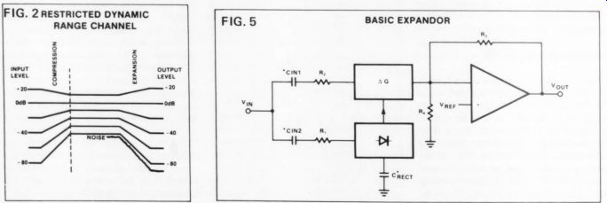
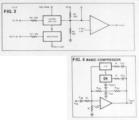
Fig. 2 Fig. 3 Fig. 4 Fig. 5
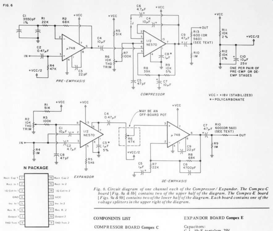
Fig.
6. Circuit diagram of one channel each of the Compressor/ Expandor. The
Compex-C board [ Fig. 8a & 8b] contains two of the upper half of the
diagram. The Compex-E board [Figs. 9a & 9b] contains two of the lower
half of the diagram. Each board contains one of the voltage splitters in
the upper right of the diagram.
--------------
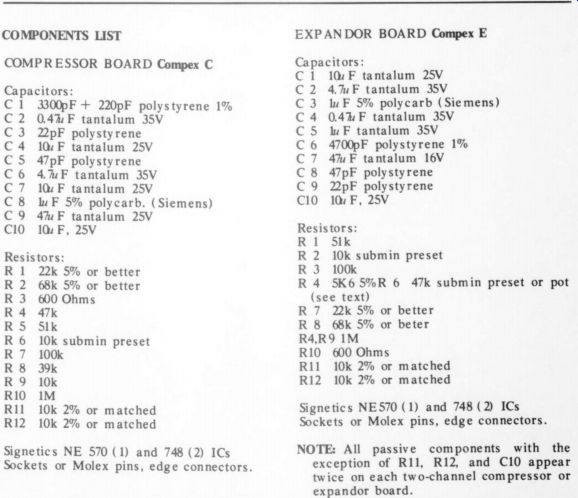
COMPONENTS LIST
COMPRESSOR BOARD
EXPANDOR BOARD
Compex E capacitors:
Signetics NES70 (1) and 748 (2) ICs Sockets or Molex pins, edge connectors.
NOTE: All passive components with the exception of R11, R12, and C10 appear twice on each two-channel compressor or expandor board.
----------------
If nothing else, it will serve as a valuable and practical introduction to the use of compandors per se. It also avoids the rather crude control mechanisms devised for some other previous designs, such as those using physically coupled lamps with photocells or thermistors with their in determinate attack and decay times, usually too slow.
Central to this design is a newly available integrated circuit introduced by Signetics.(4) The NE570 7/571 was designed principally for telephone routes in the USA, where degradation due to noise is more likely on long trunk circuits or even long subscriber's lines. Naturally, since the device was engineered for narrow band speech channels with an upper limit of about 3.4kHz, some difficulty was expected in attempting to design a compandor for wider bandwidths, up to say 20kHz.
Fortunately, the need for concern proved to have more substance in theory than in practice. My prototype was designed initially for the Norwich Hospital Radio Broadcasting station, where circumstances sometimes required the relay of program material during outside broadcasts over circuits of nominal 600 ohms impedance and somewhat noisy.
As such, it works exceptionally well and in fact, with the system connected back-to-back, it takes very careful listening to tell when it is in circuit or bypassed. We will be using the NE570 version of the Signetics device, since this has tighter production spreads so eliminating the need for extensive trimming techniques to optimize performance. The chip contains two identical circuits, consisting of the variable gain cell, an averaging rectifier which produces the cell's control current from the in coming signal and an operational amplifier of the 741 type and internally compensated. (Fig. 3) The whole configuration may be connected in one of two modes; with the gain cell and rectifier in the feedback loop of the op amp, whereupon it operates as a compressor on a deci-linear scale (Fig. 4);
or as part of the input circuit to the op amp in which case, it now functions as an expandor with an action complementing that of the compressor (Fig. 5). Distortions, mainly spurious harmonic products, occur in the gain cell due primarily to dissimilar offsets in matched pairs of transistors connected differentially. These products are mainly 2nd harmonic and fortunately, may be can celled out almost completely by means of a trim facility on the chip. I felt this trim facility was the only one worth retaining in this particular design.
--------------------
TABLE 1 COMPRESSOR
Input Z: 47k Output Z: 600 Max. input level at 1kHz: 235V.RMS Max. input level at 5kHz: 1.22V.RMS Max. output level at 1kHz: 1.95V.RMS (equal to + 2dBm terminated)
EXPANDOR
Max. input at 1kHz, 5kHz: 1.95V.RMS Max. output at 1kHz: 4.9V.RMS (equal to + 10dBm terminated) Input Z: 6.5k Output Z: 600
----------------------
Special note: The low input Z of the expandor may create interfacing difficulties with some tape recorders. In such cases a simple buffer amplifier, such as a single common collector stage may be necessary.
( See TAA. 4/ 77 for a suitable IC unit.) Another source of distortion arises within the rectifier. Here we have to consider a trade-off situation between fast response and low distortion. If a small value of integrating capacitor (C rect) is used to get very fast attack and decay times, some ripple will appear on the gain control line as harmonic distortion. The actual amount is inversely proportional to both frequency and the value of the capacitor and typically, one would expect about 0.2 percent at 1kHz with 1 uF(0dBm). Fortunately, if the values of capacitor in both compressor and expandor are identical then the distortion products are cancelled out.
For this reason, as well as the obvious one of aiming for identical dynamic envelopes, this capacitor should not only be the same value but ideally, of close tolerance throughout. I found that a value of 1uF was about right, producing attack times of about 1.5mSec and a decay of about 7mSec. The compressor is preceded by a pre-emphasis stage to reduce 'breathing' faults.
Frequencies above 500Hz (+ 3dB) are progressively enhanced in level, up to a maximum of +12dB at 5kHz and flattening off to about 20kHz, then falling beyond that. This action is complemented very accurately by a de-emphasis stage following the expandor. The pre emphasized signal is applied not only to the op amp stage but to the gain cell and the rectifier as well; so what emerges from the compressor is a signal with an amplitude response curve that is half the original, ze. rising to a maximum of +6dB, not +12dB. This fact must be taken into account when feeding the compressed signal into the transmission medium or tape recorder; and in the latter case, if peak reading meters are not used for level control, then it might be wise practice to reduce the maximum record level by about 6dB-dependent upon the program material, of course.
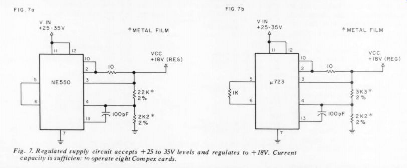
Fig. 7
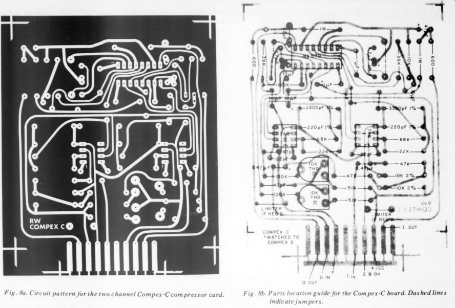
Fig. 8a. Fig. 8b. Parts location guide for the Compex-C board. Dashed lines indicate jumpers.
The gain of the expandor is adjustable to a limited extent and a control h0 (Fig. 6). If the constructor prefers, these points on the board may be brought out to an independently mounted, ganged gain control instead of a pre-set on the board itself, but remember that all leads are standing at +9V potential.
Adjustment of the THD trim should be done with a harmonic distortion meter, preferably in conjunction with an oscilloscope so one may also examine the nature of the distortion products. The compressor and expandor must be adjusted independently and to prevent masking of the products arising within the rectifier, it is recommended that the integrating capacitor be temporarily shunted with one of considerably higher value, say 100 uF. It should be possible to trim the Dt products down to below 0.1 percent at an output of 1.5V RMS at 1kHz; equally, it should also be possible to adjust to the same level for an output of 2V. from the expandor. Aim for symmetry in the harmonic products which will be predominantly 2nd harmonic.
The overall system should also be well below 0.1 percent, mainly second harmonic. In the prototype at the terminated level of +9dBm from the expandor, the total harmonic products at 1kHz were about 0.08 percent. Frequency response was linear from 40Hz to 25kHz within a spread of 0.5dB and static tracking ac curacy was also within 0.5dB from 8dBm down to -60dBm. Unweighted output noise was entirely due to the de-emphasis stage and measured about 50 volts.
This suggests that if one does not want to worsen the effects of system noise-say, to keep this to better than -70dB-then it is good practice to ensure the operational level is above 150mV at least. If the constructor feels it is worth the extra expense, then one of the many superior versions of the 748 might bring some marginal improvement; but frankly, I feel it would be more profitable to select individual 748s.
One final point, it is wise to keep the record levels through compressor and the expandor as close as possible; without going into any great detail, suffice it to say that the attack and decay times are not identical at all working levels. While this small defect could be corrected by more complex circuitry, I felt that most constructors would be able to observe this small requirement in actual use.
---------------17
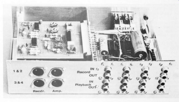
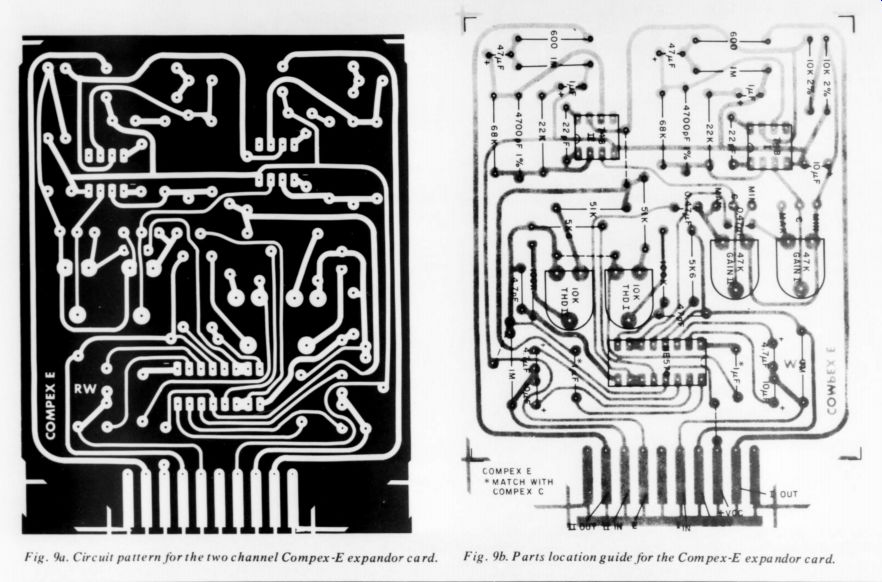
Fig. 9a. Circuit pattern for the two channel Compex-E expandor card.
Fig. 9b. Parts location guide for the Compex-E expandor card.
CONSTRUCTIONAL NOTES
I strongly recommend that the etched circuit boards be used in building the circuit (Fig. 6). You will note that the functions of compressor (Fig. 8) and expandor (Fig. 9) are on separate boards, two channels per board. We felt that there would be little virtue in combining compressor and expandor on one board--except, perhaps, the avoidance of two boards to design instead of just one. Most users will require two channels of both functions for stereo and there are also operational circumstances where the two functions will be geographically separated.(5) The boards are compactly designed without overcrowding or using rare components. Nevertheless, there is little spare room so careful soldering technique is vital as with all boards using integrated circuits. Provision is made for using 10 way edge connectors of 0.156 ” pitch, which should be easily available with gold contacts, although silver is quite adequate for the levels used. It may be necessary to cut “shoulders ” on each side of the edge contacts, depending upon the style of connector you choose.(Old Colony board will be supplied notched.) The contact sequence is identical for both the compressor and expandor boards.
It is also recommended that IC sockets or Molex pins be used and that the NES570 7 748s not be soldered directly to the board. Fit all the resistors first, then the pre-sets, followed by the polycarbonate 1uF units and all the polystyrenes.
Where the few “jumpers” are needed will now be more obvious. The last parts to be fitted should be the tantalums. Check their polarity carefully since they are easily damaged by incorrect connection.
Before applying power, check the solder side of the boards very carefully for odd dry joints or solder “whiskers. ” It isn't too fussy to do this with a magnifying glass, either. A mistake will always be expensive! The ICs are clearly marked at the pin 1 end of the case and should be carefully inserted last. One final constructional point, unless one wants to retain an exact 600 ohm output impedance-and resistors of this value are a bit 'difficult' -it may be substituted with one of 560 ohms.(Or two 1200 ohm.- Ed)
FUNCTIONAL TESTS
Apart from the obvious ones, such as overall frequency response, etc., the first important test is to try the system back-to back and insert it in say, the Tape Out and Tape In sockets of a hi-fi system. Feed through and listen to a variety of program material, such as music and speech from both records and FM radio. If it all sounds acceptable, then go on to feed the signal via a tape recorder. Be ready for initial disappointment, since most domestic tape recorders and cassettes in particular, have record / replay amplitude errors which are on the margin of being acceptable. So here, it might be necessary to effect some improvements before results with the compandor also become acceptable.
Other factors may influence dynamic tracking accuracy, such as any constant amplitude signal present on/y during the compression or the expansion process.
Two such examples are spurious sub carrier components from an FM stereo tuner or the bias from a tape recorder.
There are sound arguments for inserting into the system bandpass filtering with sharp attenuation slopes at say, 40Hz and 20kHz. It is a little early to say whether this extra complication and expense is desirable-but if it proves to be so, then a suitable design will be published later.
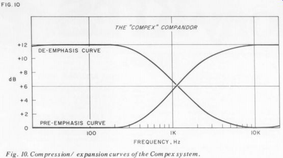
Fig. 10. Compression/ expansion curves of the Compex system.
POWER SUPPLIES
[...]
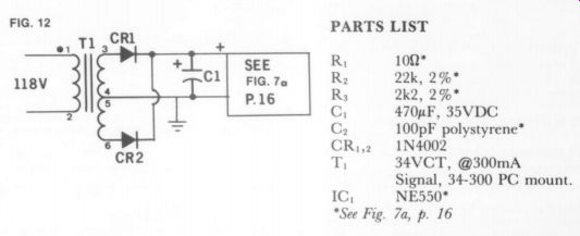
trimmed for minimum THD, this ac curacy will be preserved as well as optimum performance in other respects. A suitable circuit is illustrated and will supply up to eight dual boards without difficulty (Fig. 7a or 7b).
Alternative methods of setting up the THD trim without a distortion meter proved an insoluble problem and the writer is open to suggestions. But an experiment was tried in which the pre-sets were set at their physical centers and the THD checked for twenty off-the-shelf NE570s. In no case did the THD exceed 0.5 percent (0dBm) and many constructors may find this acceptable.
If not, then Old Colony Sound Lab will be offering a setting-up service for which there will have to be a charge, of course.
The boards must be working and free of faults. They should be sent, well packed and with a return address label with a remittance of $3.00 per board for adjustment and return via UPS. Please use a street address for return shipment or add $1 for insurance via parcel post. The THD will be trimmed on an accurate 18V supply and will always be less than 0.1 percent on return to the constructor. Old Colony ( Box 243, Peterborough NH 03458), cannot undertake to remedy faults in boards sent for this service.
My acknowledgements to Nigel Reynolds and Tom Woodford for considerable assistance in the prototype construction and to Alan Watling for the final board design, photos, drawings and his infinite patience with a designer who rings up at the eleventh hour with yet another modification
REFERENCES:
1. Audio Amateur, “What is PCM ” 3,4/ 1975, Reg Williamson.
2 Journal of the Audio Engineering Society, October 1967: “An Audio Noise Reduction System” Ray Dolby.
3. Hi-Fi News & Record Review 'dbX' by Frank Ogden, Oct. 1976.
4. Audio Amateur, Walt Jung & Craig Todd, “Operation and Uses for the 570/ 571 IC Compandor Chip ” 4/ 76.
5. A forthcoming TAA article by Walt Jung will put switchable compressor/ expandor units on a single board.-Ed.
------------- PARTS LIST
--------------------------
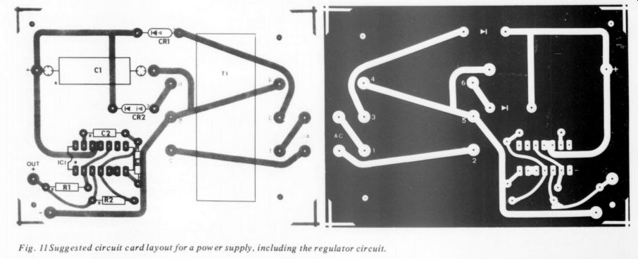
Fig. 11 Suggested circuit card layout for a power supply, including the regulator circuit.
by REG WILLIAMSON, Contributing Editor
----
Also see:
Test Report: Listening tests of the PAT-5/WJ-1A, by Laurence L. Greenhill, M.D.