The PAT-5/WJ-1A: A PAT-5 WJ-1, DC coupling, FET inputs and new insights into cleaner sonics. Update by Walt Jung and Dave White.
IN THE FIRST ISSUE of 1978 we described a modification to the Dynaco PAT-5 preamplifier which consisted of new power supply and phono cards and also a number of high level changes. From the feedback from field executions of these changes, TAA readers have generally been pleased with their results, and a number of them have chosen to say so in the Letters column.
While we are pleased the circuit has been generally well received, we have in the meantime been investigating methods to improve it further. No design is perfect, and the audiophile by nature pushes constantly for better sound quality. As the original article fairly well described, the PAT-5/Wj-1 is a design which conventional test these ratings relate to sound quality is, we believe, a fair and natural question.
To answer it is the reason for this article.
Listening test comparisons with the best top quality “high end ” preamps found the original PAT-5 wanting. We undertook a program to determine what specific areas might yield audible improvements, yet still be realized within the general PAT-5 chassis framework.
We found many things which rather strongly affected relative sound quality, but often had little or no relation to measurable parameters. The changes which we describe below are a summary of these findings, in terms of what can be done to update the PAT-5/WJ-1 further. We present them in a manner which allows you to include as much as your individual taste (or pocketbook) may dictate. The constructor should be forewarned that many of these changes are difficult, and some are a decided pain. But we would not propose them here if we did not believe each one represents a definite step toward improved sound quality.
RATIONALE
Before describing the changes, a word is appropriate on why we advocate them at all. It has become increasingly evident to us that as one improves the overall capability of the sound reproduction system a great many degradation factors arise. Many of these factors are often controversial, many scoff at some of them. Two general system examples involve exotic wiring: gold tipped phono cabling, and “super ” speaker cables; as opposed to more conventional inter connections.
Generally, in our experience, as you climb the ladder of sound quality, virtually everything becomes important to performance. Of course, some of the possible improvements have a larger relative effect than others, but even the smaller ones are nevertheless still significant.
It also seems to us true that some systems exhibit masking effects which can prevent detecting the more subtle differences, either in the power amp, preamp, speaker, or a combination of them.
We are well aware that one school of thought says that when the frequency response and signal polarity differences are normalized between different preamps, they then all sound alike (see Letters 2/79, and in this issue). We distinctly do not agree with this theory, for several reasons.
We are able to hear a multitude of differences in amplifier circuitry, unrelated to frequency response or polarity. In deed, when all the potential factors discussed below are permuted, we have a virtually infinite series of different sounds with the same (static) frequency response and polarity. It may well be a fact that certain individuals cannot hear them in a given system, but that fact does not prove they do not exist.
EARS AS ARBITERS
We also recognize that since the audibility of errors is an area of such controversy, the statement of our beliefs (one way or the other) will probably do little to change the overall picture.
Therefore we will present little in either arguments or technical data to persuade the reader that a given change is necessary, or that our technique is effective. While we do have what we feel is convincing supporting data in many cases, we believe the reader is more interested in eating than in recipe details.
As a matter of interest, virtually all the changes here described were evolved by a listening process with only occasional bench checks. This is not to say that instrument tests are worthless, or no longer valid. It is to say that if you are interested in pushing hard toward state-of-the-art, in our opinion you can not get there solely with presently available testing measurements. Too much is simply not yet fully understood, in too many areas.
We believe that one must listen long, hard, and carefully, making changes one at a time, and evaluating each on its own merits. Let the ear be the final arbiter-as it should, bearing in mind that our sound systems' fundamental purpose is to give us pleasure from the reproduction of music. If they do not do this, something is wrong. If we make a change which clearly results in audible improvement, but which cannot be measured, we must not dismiss it as in valid. If the sound quality change is a real one, it will also be repeatable, for similar conditions. In time our measurements will catch up with our ears. Meanwhile, why should we deny ourselves the pleasure of better sound because it doesn't fit pet theory or meter?
someone's
DEVILS & DOING
To forestall (perhaps) some of the accusations of unscientific methodology, or “selling out ” to cultism or audio witchcraft, we'd like to counter such possible criticism with the old saying, “don't knock it til you've tried it. ”' We believe it is definitely applicable here, and action may make believers of many potential critics. A prior: criticism, based on principles “known to be right, ” is an easy technique, and some of our changes are certainly at variance with some accepted principles. However, we believe we achieve more progress when we try things which give results, without being bound by closed-mind attitudes. Subjective audio is, by nature, like dealing with the devil. We are asking for a reserved judgment before you try our suggestions or say it can't be so.
matters, or just too often take them for adds new LM317K 15V TO-3 two For those interested, we have asked independent critics to review these design changes in the pages of their publications. Some commentary on the PAT-5/Wj-1A should also be appearing in a future issue of Stereophile magazine.
WHAT ARE THE CHANGES?
[…] and the phono circuit. We are designating the total of all these changes as the WJ-1A modification. The individual modifier may incorporate as many or as few of them as desired. We offer specific suggestions about their execution in step-by-step instructions, and a preface discussion to each section describes the resulting sonic differences.
POWER SUPPLY
The most dramatic of the sound improvements occurs when we lower the power supply regulation impedance. In general, designers of high performance audio appear to neglect power supply granted. However, if the power supply offers a very low broadband impedance to the circuit, non-subtle sound improvements can occur. Transients become more life-like and prominent, with an increased and much more natural dynamic range. Localization and separation of instruments is much more detailed and stable, with the result that some recordings sound like parallel mono (which many multi-track are, of course). Over all, the sonic character is more open and robust, with no suggestion of starvation, or limiting.
The power supply may be modified at three levels and one can hear differences in results by doing each of them. The first and simplest step simply shunts an extra 5,000 to 10,000uF of low ESR (Equivalent Series Resistance) computer grade capacitance across the +15V busses, increasing the current reservoir and lowering the buss impedance at high frequencies. An allied part of this change is the addition of two 5uF mylar capacitors, for very high frequency bypassing.
The second step adds additional regulator input capacitance, which further improves regulation. Step three regulators, resulting in tighter broad band regulation. This step, combined with the first two, reaches a point of diminishing returns in sonic effectiveness, as such other things as wiring impedance and local bypassing become the predominantly limiting factors.
DESIGNS WANTING
In general, power supply design is more critical than is usually imagined because the supply terminals of the amplifiers (IC, or whatever) may, to some degree, be regarded as signal terminals. Particularly is this true at higher frequencies, and our research suggests this effect is operative well into the ultrasonic region. If you doubt this, connect an amplifier to a load with no signal and pulse the supply lines while observing the output on a scope. You'll see what we mean.
To make the power supply changes, follow the step-by-step procedure in section PS. While this procedure is written for the W]J-1, much of the theory is equally applicable, we believe, to other preamps. Try a pair of the specified 6300uF and 5uF caps in any preamp ...
==================
BOX PS: MODIFICATIONS to the POWER SUPPLY
General Instructions: Read through this entire list, take stock, and decide how extensive your modifications are to be.
Please note that the order is important in some cases, for ease of execution and placement. If you make all changes, the logical sequence is 3, 1; 2.
1. Add 6300uF/25V computer grade capacitors (2) across (+) and ( -) 15V power busses. Physically locate these just behind the vertical partition, but close to PC-34 cards. Use #16 (or larger) wire with a short length to wire these two points to the PC-34 (+) and ( -) 15V interconnection busses. Very carefully observe polarity when connecting these capacitors! The 5uF mylar caps are part of the power supply circuit, but are physically located on the PC-34 cards. Thus their installation is covered in the high level changes.
2. Add 8000uF/30V computer grade capacitors (2) across C, and C4, of JW-32 card. Leave C,_4 on card, wire each of the two new capacitors electrically in parallel with the old ones; physically attach wires to existing C; and C, leads. Make absolutely certain the polarity of both new capacitors is correct: (+)to(+)and(-)to(-). Physically mount these two caps behind the first two (step 1), near the outside edge of the chassis. Position all four units carefully to avoid interference between mounting clamps, etc. Wiring of these two capacitors can be done with #18 wire as it is less critical, but user larger if you can.
Special note for steps 1 & 2: with both steps (1) and (2), make sure that both (or all four) filter capacitors are fully seated into their mounting clamps, and rest firmly on the chassis bottom. This is necessary if the top electrical connections are to still allow the outside cover to be installed.
Fig. PS-2: New power
supply filter/regulator schematic. Underlined values are mounted
on the chassis partition, “B ” designations are replacements of previous
numbers. Note wire sizes. These zeners (15V, + 5%, 0.5 W) may be salvaged
from the original Dyna PAT-5 kit, do not substitute.
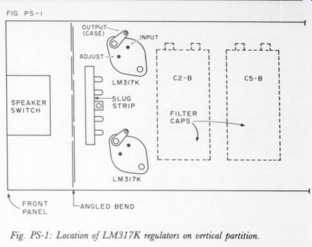
Fig. PS-1: Location of LM317K regulators on vertical partition.
However, even when fully seated, the clearance margin is near zero, and shorts are likely unless one takes positive steps to prevent them. A piece of cardboard or 1/16 ” polystyrene larger than the total area occupied by the capacitors should be cemented to the chassis lid, as a minimum. In addition, cementing a similarly dimensioned piece of foam insulation 1/2 to ¾” thick (scrap carpet backing does nicely) over this area and that above the JW-32 card is a good idea. The cover will then need to compress these foam pads somewhat, resulting in a positive clamp for the JW-32 card. This will also prevent JW-32 card and transformer vibration, which is certainly possible if the unit is transported. If you ship your unit, this latter step is a must.
------------------------------
Installing the LM317K regulators.
3. Remove wiring from JW-32 card to the two chassis mounted 7815 three-terminal regulators. Remove any solder blobs remaining on the PC card where their three leads were attached.
Install two new LM317K TO-3 style adjustable three terminal regulators on the vertical partition, just behind the angled bend near the chassis front. The two near capacitors installed in (1) and (2) above must be temporarily removed in order to drill the necessary holes. A 5-lug (center ground) terminal strip should also be installed here to mount the four components associated with this change. See the diagram below, Fig. PS-1. The easiest way to drill the holes is to remove the vertical partition from the main chassis temporarily.
Locate the LM317K mounting holes as shown, allowing for clearance between the nearest filter cap and the 5-lug strip.
Carefully drill and deburr the nine holes. Mount the LLM317Ks from the opposite (inside) side of the vertical position, using a pre-greased silicone TO-3 insulating pad and shoulder washers for the two mounting screws. Do not use a socket. Wire directly to the terminals of the devices to avoid the socket losses. The underscored components noted in Fig. PS-2 are those which are mounted and wired on the partition before it is re-installed.
Wire in these components following the new schematic as shown in Fig. PS-2. This hookup shows only the details of the newly added components, not all those in the power supply circuit. Note that the new filter caps are given “B ” designations, which identify the corresponding original capacitors they augment. The new regulators are purposely located very close to the +15V filters, to minimize wiring impedances. Use no longer wire lengths than necessary, with #16 (or heavier) where so indicated. This new configuration places the + 15V regulation points on top of the new filters, C; 5 and C;s_5. We suggest you use 1N4002 diodes as shown, as protection across input and output terminals in case of shorts, and across the outputs of the supply as shown in Fig. PS-2.
The additional resistors and two 0.47uF/250V polypropylene capacitors are not mounted on the JW-32 card. Mount the two 120 5% resistors, paralleled with 1N4002 diodes on the LM317Ks, and the zener diodes and 0.47uF/250V caps on the four free terminals of the 5-lug strip. Carefully match polarity of the diodes to the electrolytics, and make sure they are correctly installed in the circuit, as noted in Fig. PS-2.
On the original JW-32 card there were two 6.8uF tantalum capacitors across the +15V inputs. They should now be removed.
Notes on parts for PS modifications:
Use the best quality materials you can obtain. In the prototypes we used the following, which are recommended. If capacitors, it is up to you to check the fit!
Caps: 6300uF/25V Sangamo, series 500
Caps: 8000uF/30V Mallory Source: Hanifin Electronics, Box 188, Bridgeport PA 19405 (800) 523-0334.
Both must be 3 x 1 “ can size. You also need four 1” clamps and eight #10 lugs.
Resistors: 12 0-ohm +5% carbon.
Capacitors: 0.47uF/250V polypropylene.
Diodes: Six 1N4002.
Zeners: Two 1N4744A 4 W, +5% (15V), salvageable from original Dyna supply. (Do not substitute other zeners for IN4744A.)
Regulators: National LM317K (TO-3 case). No alternative types are suitable here.
you use other
Source: Jameco Electronics, 1021 Howard St., San Carlos CA 94070
===============
...with 1,000uF or less supply line bypassing, or simple zener regulation, and listen for the difference in performance.
THE PHONO CARD
The changes in the JW-33 phono card at first appear to be extensive, but considering the relevant factors, are necessary to the type of improvement we want to achieve. Some of these changes become necessary because of a ricochet effect, which requires some explanation for proper perspective.
One of the problems associated with the JW-33 card in the original WJ-1 is caused by the use of tantalum coupling capacitors.(See Dick Marsh's letter on capacitors TAA 2/79, p. 54). They can give the sound a grundgy, grainy, or sandy high end, as well as a serious veiling and loss of sonic resolution. So one of the objectives of this update was to solve this specific problem as well as possible, while still remaining within the confines of the general physical design.
At first it appeared that selection of an optimum tantalum type might do the job, suitably bypassed with a smaller unit for HF smoothness. This proved to be a stop-gap solution at best however, and one which still employed a capacitor. The best coupling capacitor, it appears, is no coupling capacitor at all; if this is not possible the capacitor's effect should be minimized.
BIG POLYPROPYLENES
One easy minimum capacitor solution is to simply jumper C; and C,; on the JW-33 card, and use a single off card coupling capacitor for output DC blocking (the function of C3). With the input to IC, on the card direct coupled (as originally described) this can work successfully in many circumstances, as the offset voltage of the 5534A op amp is typically less than 1mV. This would typically result in an output offset of 0.5V or less (with cartridge connected) for gains of 34dB or less, which imposes no real limitation of dynamic range at the output. Unfortunately, an optimum output capacitor for use here has three problems: it is large, expensive, and very hard to obtain. It should be a polystyrene, polypropylene or polycarbonate type, 50V rating, and 5uF or larger size.
While many may opt for this solution, we believe it to be a compromise in terms of convenience and cost, as well as it to be a 20uF cap, but that's really out of the question.) Nor does this solution eliminate the bias current in the cartridge. Although four different cartridge manufacturers, to date, have informed us that the 500nA bias current of the 5534 is negligible, many readers are apparently worried about it, since they keep raising the question. And, the un controlled DC source resistance presented by various cartridges is a real offset problem (for an op amp with the level of bias current typical of the 5534).
SERVO SETUP
An alternative solution, which appeared at first to be quite radical, is the use of a low offset voltage FET op amp, and a local DC feedback loop. This loop, a electrical performance (ideally we'd like -continued overleaf
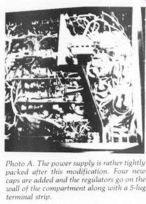
------------- Photo A. The power supply is rather tightly packed
after this modification. Four new caps are added and the regulators go
on the wall of the compartment along with a 5-lug terminal strip.
=================
OF EXPERIMENTAL METHODS and CIRCUIT CARD CLEANING
I MAKING CHANGES to effect improvements in the PA'T-5/WJ-1(A)'s sound quality Walt and I have consistently followed a standard series of steps:
1. Make the change
Listen for an audible difference
Evaluate the change for sound quality.
Determine the engineering reason for the difference, if possible.
Measure the results
[...]
tell the difference between the two devices although I could not measure any frequency response differences (>0.05dB).
Because masking is a very serious problem until you reach a certain point I strongly recommend the power supply modifications as a first step.
When I made the power supply changes I was impressed by the sonic difference. 1 then took the preamp up to a friend's lab and we attempted to measure frequency response and distortion differences. The only change was in the 2nd harmonic distortion at 1kHz: unmodified 106dB (.0005%); 116dB (.00015%). The distortion at the frequency extremes and the frequency response remained unchanged. The subjective differences are modified: an immediate increase in separation and what seems a to be a pitch change.
transients seem to come alive I now have the means at my bench to measure dynamic power supply performance. The new measurements correlate perfectly with the subjective changes although I cannot relate them to the standard measurements.
I suspect the static, is measured at a single frequency, versus dynamic, frequency will vary response with different power supplies and circuit We hope in time to pull together our research and to present it in some orderly fashion topology.
A few tips on board construction: Before assembling your etched board wash it in a dilute solution of water and Spic and Span . This will dissolve any manufacturer's salts that may be left on the board. Rinse it well and dry it thoroughly. As audio circuits are normally high impedance, high humidity can ionize the salts and cause shunts in the circuits. Clean your boards as well after soldering since flux and other residues can cause long-term problems. Be careful when using cleaning solvents such as contact cleaner or alcohol which can dissolve plastic in polystyrene capacitors and shorten the life of rubber end caps on electrolytic capacitors. This is one reason why polystyrene capacitors are seldom used for commercial work despite their excellent performance qualities. - Dave White
==============
....servo, serves to hold the output of the JW-33 card within a few millivolts of ground, and continually corrects for temperature and long-term drift, as well as the initial offset. While a given set of amplifiers may be trimmable to zero output offset, this is not a practical solution, for several reasons. A few degrees change in temperature, at the IC (or the cartridge) can result in many millivolts of output offset, so such a method is un predictable in practice and cannot be recommended.
The solution we finally adopted employs the circuit shown in Fig. PC-1 of Box PC. In this circuit IC, is an OC 2N op amp, a FET input device manufactured to Old Colony specifications, and one considered optimum for this application. It has a bias current under 100pA, and low input voltage noise. Gain determining resistors Ry -R, give a 1kHz gain of 33.7dB. While this produces somewhat lower gain than previously, it is better for the volume control to operate towards the 12 o'clock position, where tracking is better.
It proved impossible to incorporate a complete servo loop on the existing card, but fortunately a minor modification to the track pattern allows an external ser vo control signal to be coupled into IC.
This mod consists of cutting the ground track to IC;.3 in two places, and drilling four holes (#60 drill) spaced for two 0.25 W […]
SERVO CONTROL: WHAT & WHY
The servo system used in this modification functions primarily to null the residual DC offset voltage and drift of the phono circuit. With DC coupling of an RIAA equalizer, the DC gain will be approximately ten times the 1kHz gain (60dB or 1000 times, for 40dB; or 100 times 1kHz gain). Therefore 1mV of DC input offset (a relatively low specification value) will become 1 volt of offset, at, the phono stage output. The servo serves to automatically null this offset to much lower limits, on the order of 10mV or less.
While this is a thumbnail sketch of what the servo loop does in the Wj-1A, it gives no insight into why this approach was chosen. The major reason is simply that it provides a sonic purity unattainable with the use of coupling capacitors. In a system which is free from other masking sources, the elimination of coupling capacitors and their inevitable grundge can be very revealing in terms of sonic improvement. From our experience (at this writing), the only large value coupling capacitor which comes close to a hard wired DC signal path is the TRW X363 UW type. There may well be others, but we have not discovered them yet.
Some comment on employing the ser vo and total DC coupling of the Wj-1A mod is appropriate for the potential builder. You should undertake this venture with an appreciation of its implications, and the understanding that it is up to you to make sure it is working correctly. Obviously it is not a project for the novice, and you will require a DC voltmeter with 10mV resolution to check the operation. Old Colony Sound and the authors are not equipped to troubleshoot individual preamps. We do not mean to intimidate you, but you should understand what you are getting into.
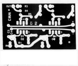
-------- Fig. PC-7: Negative pattern of the WM-3 circuit card.
It is two channel, thus two DC servo controls may be mounted on it.
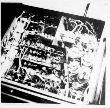
---------------Photo B. Overall view of the PAT-5/Wj-1A. Note the high
level boards have large polypropylene capacitors between the two boards.
The phono preamp boards, no longer in plug-in mode, are inverted for
convenience.
HANDY CARD
The servo is implemented by using a new card (for this application), which contains two integrator circuits. The integrators employ low bias current op amps, with their inputs wired to pin 6 of the JW-33(A) card; their outputs go to pin 10. The schematic of this loop is also shown in Fig. PC-1.
The servo loop holds the JW-33(A) output to within the offset voltage of the IC used; for the LM-308 this will typically be 5mV or less. The time constant is purposely set long to prevent any LF rolloff. Time required to zero at turn-on is about 30 seconds. Note that a low-leakage capacitor must be used in the integrator for it to function properly, such as polystyrene, polypropylene, or polycarbonate. We were not able to detect any undesirable side effects with the use of this circuit in listening tests.
The nice thing about it is that it costs much less than the two 5uF capacitors it (functionally) replaces.
Other changes include modification of the supply line decoupling, and are tied in with the power supply changes noted above. C; and Cg are removed, and Co.12 must now become non-inductive Mylars . A pulldown resistor, (Rg, 6.8k) on the output of IC; forces it to operate class A, for optimum linearity, and best sound quality. R; and R, are replaced with new values as shown in Fig. PC-1.
==================
BOX PC: Phono card modifications:
Direct Coupling of JW-33 phono preamp card: Note: this procedure is usable with a 5534 for IC,, only if you have the input circuit directly coupled to the cartridge, as originally shown in TAA, 1/78 Fig. 4c, p- 8. If you have elected to use the input capacitor as described in TAA 2/78 Letters, you will have to change the circuit to the DC coupled input to use this modification. With the OC-2N FET op amp, the input should also be DC coupled as well, but there will be no bias cur rent in the cartridge (see text). We recommend use of the OC-2N op amp for this modification, for best results.
Preliminary:
With power off, temporarily short coupling capacitors C, and Cs on JW-33 card using short wires, soldered in place. Turn the level control completely down, and re-apply power. With a DC voltmeter measure DC voltage at pin 6 (output) of the card. With a cartridge connected and using the 5534 as IC, it should measure less than + 1.5V DC, and be steady.
With the DC offset limits thus verified, turn off the power and remove the ICs from the card, and solder the new ones into their respective positions, removing any sockets previously used. Sockets cannot be used if high quality audible results are desired. Before soldering IC, into place, drill two holes in the tracks to pins 4 and 6, just to the right of the IC. Space them for a 0.25 W resistor (Rz, 6.8k), using a #60 drill. Install Rz on both phono cards, in this manner.
Remove capacitors C; and Cs from the card, and replace with buss jumpers, soldered into their places. Remove R3 and R4. Replace R3 with an 18.2k, and R4 with a 13.3k (both + 1% metal film, 0.25 W.) Note: the above preliminary steps are necessary for either the output capacitor or the DC servo loop options.
Output capacitor option:
On the chassis, adjacent to the JW-33 cards and under the selector switch, mount two 5-lug terminal strips with the center terminal grounded. These should be about 2.5' “ apart. Between these strips mount two film coupling capacitors, as shown in Fig. PC-4. These capacitors are wired in series with the output of the two JW-33 cards, one per channel, as shown in the upper right corner of Fig. PC-1.
On the output (selector switch side) of the two capacitors, connect two 1Meg, 0.25 W resistors to ground, to prevent switching pops when selecting PHONO. The ground point is not critical for these, and the ground lug of the terminal strip is O.K.
These film capacitors should be 5- to 10uF units, with a voltage rating of 50V or more, and any available tolerance. They should be constructed with one of the following material types, listed in order of preference:
1. Polypropylene or polystyrene
2. Polycarbonate
3. Polyester
The unit(s) you actually use will most likely be dictated by your pocketbook, or your available sources. You may parallel similar smaller units of a given type, as we recognize that 5- to 10uF polypropylenes are not drugstore items. We found the TRW X363 UW polypropylene series suitable, which includes a 5uF/200V unit.
An alternative, lower-cost choice with somewhat reduced performance is the 5uF Mylar specified for the + 15V line bypasses. See high level changes.)
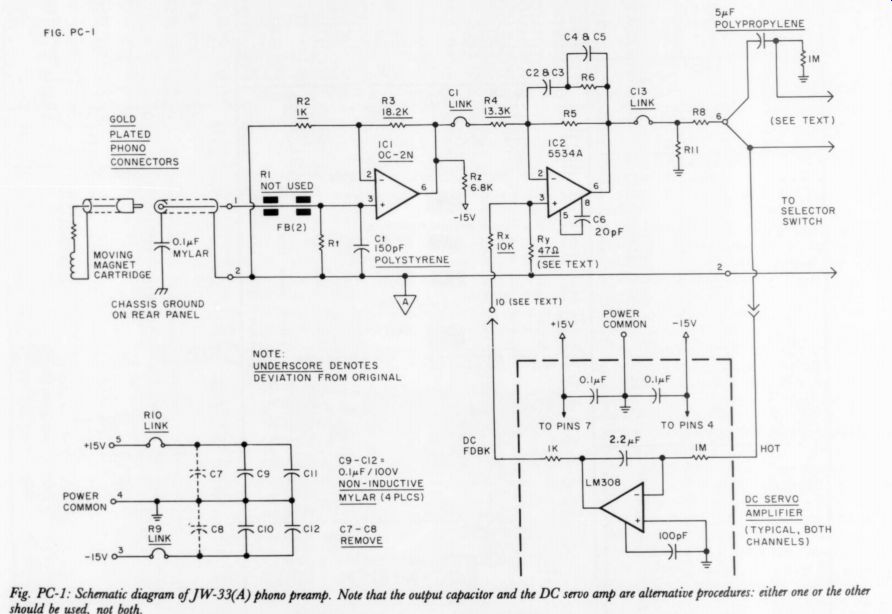
Fig PC-1
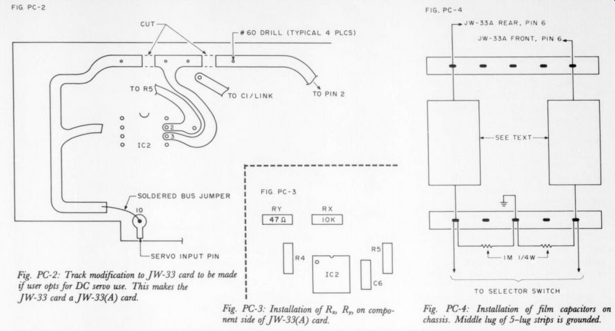
Fig. PC-2: Track modification to JW-33 card to be made if user opts for DC servo use. This makes the JW-33 card a JW-33(A) card. --
Fig. PC-3: Installation
Fig. PC-4: Installation of film capacitors on chassis. Middle lug of 5-lug strips is grounded.
Fig. PC-6 Stuffing/wiring guide of the WM-3 as a servo control
DC Servo Loop Option:
Fig. PC-5 details the hookup of the servo circuit. As you can see, this is a simple integrator circuit which is implemented using Walter Morrey's WM-3 dual buffer card (see TAA 4/77, p. 18). Since this card has two identical layouts, it nicely does the job for the two DC servo loops required.
The card assembly is best explained by the Fig. PC-5 notes and PC-6, and you may wire it with ordinary hookup wire, located directly under the selector switch (as are the capacitors). Wire the +15V lines (and power common) to the JW-33(A) card(s) power lines; the modified WM-3 card inputs and outputs are most easily wired as noted in Fig. PC-6.
[We reprint the WM-3 card as Fig. PC-7 for those who wish to make it in their own labs. -Ed. ]
If you made the DC checks on the JW-33(A) card as described above, it is nearly ready for servo use. Modify the tracks around IC; as shown in Fig. PC-2, and install R, and R, as shown in Fig. PC-3.
Carbon film, +5%, 0.25W types are suitable for this use. With the modified WM-3 card wired in, connect a DC meter across pin 6 of the JW-33(A) card, and reduce volume to a minimum. With power applied, a DC voltage will be observed (either ( +) or ( -)), which will slowly go toward zero. This voltage should settle to within 10mV or less, in 10 or 20 seconds. Check this on both JW-33(A) cards.
With this servo loop operating correctly, you will see a DC voltage at pin 10 (R, input), which is the voltage required to null the cumulative offsets of IC; and IC,. This voltage should not exceed + 12V; if it does, something is amiss. With the IC types specified, the servo design range will null the worst case DC offset limit. However this will not necessarily be true for any IC, unless its offset is 2mV or less in the case of IC, and it also is a low bias current type (100nA or less). Use a short length of shielded wire at the input, and bypass the selector switch. You simply cannot get top quality sound with these switch contacts in the circuit. Gold plated phono jacks are also recommended, as we discuss further below.
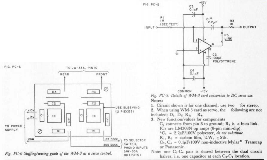
Fig. PC-5: Details of WM-3 card conversion to DC servo use.
Notes:
1. Circuit shown is for one channel; use two for stereo.
2. When using WM-3 card as servo the following are not included: D1, D2; R2, R4.
3. New function/values for components C; connects from pin 8 to ground; Rs is a buss link.
ICs are LM308N op amps (8-pin mini-dip). C, 2.2uF/100V polyester, do not substitute.
R;, Rs carbon film, 0.25W, +5%.
C3, C4 = 0.1uF/100V non-inductive Mylar Transcap or Panasonic.
Note: one C;-C4 pair is shared between the dual circuit halves; i.e. one capacitor at each Cs-Cy location.
================
The PAT-5/WJ-1A
The ICs are soldered in place (after checking), to eliminate any contact potential problems. Likewise, the JW-33(A) card itself should be bracket mounted, hard wired and soldered, at both input and output pins. Turning the two cards with the input edges upward makes access easier.
WHAT RESULTS?
The obvious question: what does all this change buy in terms of sound? Since the changes are numerous, the sound changes in several ways.
Eliminating the capacitors from the signal path cleans up HF reproduction considerably making the sonic image more open, clearly defined, and realistic. The power supply bypasses primarily improve transient response, giving more life and zip. Eliminating non-soldered contacts makes overall reproduction smoother and increases HF detail and resolution. The excellent bass response, which was always a virtue of this design, is even better with response extended to DC. This, coupled with the power supply's improved regulation, gives a very tight and solid low end.
HIGH LEVEL and WIRING CHANGES
The high level circuit modifications are relatively few, the major ones being a change of device for ICs; (see TAA 1/78, Fig. 3a, p. 12), and new controls for the VOLUME and BALANCE functions. Since a completely DC coupled signal path is our goal, we cannot tolerate a variable DC offset at the out put, to which the bias current of the 5534 gives rise. Under some conditions, it could be as high as 50mV, which, with a typical power amp gain of 20, puts 1V of DC across the speaker.
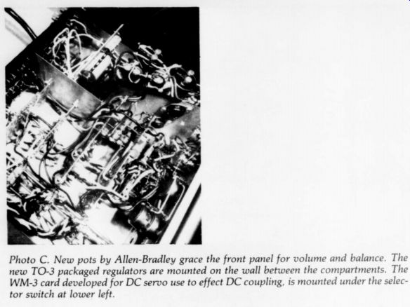
Photo C. New pots by Allen-Bradley grace the front panel for volume
and balance. The new TO-3 packaged regulators are mounted on the wall
between the compartments. The WM-3 card developed for DC servo use to
effect DC coupling, is mounted under the selector switch at lower left.
The OC-2H op amp, a low-offset voltage FET unit, has essentially zero bias current, so there is no measurable change in offset due to volume control setting. Further, Rss can now be in creased to 1Meg, which “unloads ” the volume control and removes another subtle distortion source. The worst offset appearing at the output will be no more than 11mV.
Readers may be tempted to substitute other FET op amps for ICs0,, but should do so with extreme caution (if DC coupling is used). A National Semiconductor LF357 will work reasonably well for ex ample (in AC terms), but unless the off set is trimmed, you could get 110mV of DC at the output. The LF357As are much better (2mV max offset) but are about $20 each in small quantities. A Precision Monolithics OP-17F also has good AC specs, with even less offset, = 1mV. The new ICs also improves bypassing as noted in Fig. HL-1.
CONTACTS OUT
A number of changes in the chassis wiring effect subtle but definite improvements in sound quality. For the most part these changes include steps to minimize contact problems. With the level of performance now attained by the rest of the preamp's circuitry, even a single switch contact can be noticed as a degradation.
The Fig. HL-2 signal path arrangement minimizes contact noise by improving or eliminating contacts in the phono signal path. This begins with gold plated jacks for the phono inputs, and input wiring direct to the JW-33(A) card. The card output is taken to the selector switch, as before, but also to the front contacts of the previously unused TONE switch. The arm of this switch is wired to the BALANCE control. The rear contacts of this switch section go to the LO filter, as noted. This arrangement reduces the switch contacts in the phono path to a single pair (one per side) and you simply can't do any better, unless you hard wire your PAT-5 as a phono unit only.
Allied to these changes are new VOLUME and BALANCE controls, and some re-wiring to the BALANCE control to improve sound. High quality Allen-Bradley controls are used, with minimal wiper loading.
TESTING RESULTS
If your system is a good one, and your mod totally successful, you should be able to hear just how much sonic garbage is produced in the old signal path by setting the selector switch to PHONO, and pressing TONE in, versus TONE out, which is direct.
You can add gold phono jacks as you desire, but as a minimum we recommend them at phono inputs and main outputs.
SUMMARY
After all the above discussion, the reader will probably be asking, do I really need all of this for better sound? If you need some convincing, you can try some simple, inexpensive tests to determine whether these changes are worthwhile for you.
Temporarily rewire the output of the phono card you now use directly to the VOLUME control (bypassing the BALANCE control), and listen to the preamp. If you notice a definite improvement in sound detail, you are a mod candidate. If you do not perceive any change at all, the remainder of your system may be masking the differences.
You might make the changes the first step toward a cleaner sound. Similar tests are possible using the gold phono jacks and/or cables (we like the Fulton Music Industries cable, by the way), with similar relative improvement criteria. But, these are more costly tests.
If the rest of your system is in good shape, you should perceive an improvement by this test change. If so, the remainder of the changes can help you much more dramatically.
We recognize that these changes are relatively bold, compared to those in the original WJ-1. But the concept of a completely direct-coupled preamp with a tightly regulated, wideband power supply is also a bold one. We believe most TAA readers will consider the sonic improvement effected by these changes as a definite gain. It is our opinion that the status of our present circuit is close to the ultimate limit of what we can achieve using the PAT-5 chassis.
Undoubtedly we will be asked, “Does it represent the state-of-the-art?” We believe it is inappropriate for us to at tempt an answer. We have (as mention ed) taken steps to welcome reviews by other evaluators to assess our efforts.
[See the next issue for an evaluation by David Vorhis and possibly others. -Ed.]
Nonetheless we think anyone who liked the original will be more than happy with these changes.
===============
Box HL: High Level and Wiring
The minimal step-by-step changes can be followed from Figs. HL-1 and HL-2, in order. To accomplish the changes required to install the new op amps on the PC-34 cards, unfasten the L brackets and remove the cards from the chassis, to make the PC areas accessible for modification and thorough cleaning.
Remove the 6.8uF tantalum caps used previously for Cso2 and Css. Replace with 0.1uF non-inductive Mylar units.
Take note of the changes in HL-1. Step 5
------------------
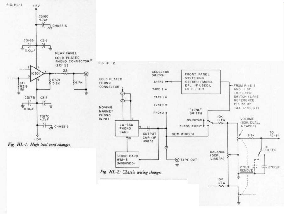
FIG. HL-I
Fig. HL-1: High level card changes.
1. Install 0.1pF/100V non-inductive Mylar |, (previously 0.01uF disc.)
2. Install OC-2H op amp for ICs0,. (Do not use socket).
3. Change Rss to 1Meg.
4. Add a 3.9k 0.25W resistor in the Rs; location. One end goes to ICs, pin 6, the other end is folded over and soldered to the adjacent -15V buss (ICs; pin 4).
5. New: 0.01uF/50V, polystyrene, Transcap. Mount on copper side of card with minimum lead length. Also, Cs;ec,
Fig. HL-2: Chassis wiring changes.
Csi7c =4.7uF/250V mounted between two PC-34 cards.
Suggested source:
Component Systems, 5556 Personality Ct., Indianapolis IN 46227. 90c ea.
-------------
is best done after cleaning of the card with all other steps already accomplished. You should especially be careful around pins 3 and 4 of ICs, as residual flux can create a leakage problem with the FET op amp. We recommend cleaning and drying the card thoroughly before use. Use alcohol, rosin flux remover (Rawn Co., Spooner WI 54801) or Waldom's Contact Cleaner.
In wiring the new signal path changes (Fig. HL-2) use minimum length stranded hookup wire. Make sure all solder connections are clean and solid. Note that the 270pF cap on the HF switch (if used before) is now removed.
Wire in the new VOLUME and BALANCE controls, noting the revised connections to the single section BALANCE control, shown in Fig. HL-2. You can mount the two series resistors required between the unused BASS control. We do not recommend other sources for these controls, as the Allen-Bradley units were found to have consistently superior relationship to the sound.
VOLUME: 50k, A taper, dual, Allen Bradley type JJU
BALANCE: 50k, linear taper, Bradley type JU Both units have 3/8 ” bushings and shafts.
Source: Hanifin Electronics, Box 188, Bridgeport PA 19405 (800) 523-0334.
As the PC-34 cards are re-installed and re connected, connect a pair of 5uF Mylar caps from the +15V busses between the front and back cards, to a (common) ground lug mounted on the right “U ” bracket surface.
Capacitor: 4.7uF/250V metallized Transcap, radial construction Source: Mouser Electronics, 11511 Woodside Ave., Lakeside CA 92040; and Hanifin Electronics.
The specified gold plated phono jacks are a thread-in type which can be mounted right in the phenolic rear strip, after the old jack has been removed. Just bend away the old jack's ground lug ears, and twist it out, after loosening the strip. Carefully drill a large hole in the phenolic, to clear the threaded body of the new jacks. Use only a nut to hold the gold jack mechanically, and not the unplated ground lug. Solder directly to the gold threads, since using the lug adds another undesirable contact.
single, Allen Mylar
----
Also see:
Test Report: Listening tests of the PAT-5/WJ-1A, by Laurence L. Greenhill, M.D.
Holes, Hardware and Hearing, by Rod Rees and Ron Shaffer, Can a low-fi mindset miss some beauties?