Kit Report: The Integrex Dolby Noise Reducer
by Fred M. Gloeckler, Jr.
Note: A copy of the rough draft of this review was furnished to Integrex. After corresponding about some of the points raised in the review, the author decided to revise it to reflect this discourse. We feel this practice improves the information available to our readers. Integrex promises to send one of their new, assembled, decode-only Dolby units for review.
The INTEGREX Dolby Noise Reducer is a full-function Dolby-B processor able to both encode and decode. Inputs include Aux, FM, and tape. The machine has outputs for a tape recorder and the system preamp. Front panel record level and balance controls adjust the Aux input level.
The reducer accommodates both normal and Dolby (25uS preemphasis) FM broadcasts. Dolby FM signals remain encoded at the tape output but are decoded for the main output. Holes in the front panel give access to preset level pots for FM and tape inputs and tape output. An output level control adjusts the main output. Pushbuttons activate all switching functions, including power, calibration tone, record/play (encode/decode), noise reduction in/out, check tape/source, and 19kHz multiplex subcarrier; these are in addition to the interlocked source selection switches.
The basic Integrex unit both encodes and decodes, but not at the same time; an alternate version has additional components which enable it to encode and decode simultaneously. I tested the latter version.
Audio presented the Integrex noise reducer as a construction project in its 1978 May, June, and July issues. In the May article Geoffrey Shorter, Wireless World's technical editor, described the operation of a noise reduction system in general and Dolby B in particular. The second and third articles detailed the unit's construction and use and are almost identical to the kit instructions.
Instead of repeating this generally available information, the reader is referred to the Audio articles. (Note: this project is not the same as the one presented in Wireless World a few years ago, even though the front panels look alike.)
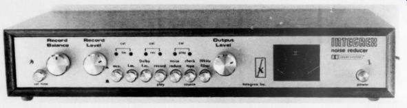
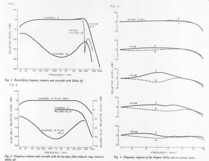
Fig. 1. Record/play frequency response and crosstalk with Dolby off. Fig.
2. Frequency response and crosstalk with the low-pass filter inductor slugs
removed, Dolby off. Fig. 3. Frequency response of the Integrex Dolby unit
at various levels
Incidentally, Bob Tucker, TAA 's national advertising representative, distributes the Integrex in the USA. I think our mutual relationship to this magazine has not biased my view.
CONSTRUCTION
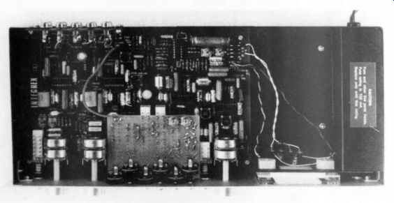
Most of the components, including switches and front panel controls, are mounted on a large circuit board. A small circuit board soldered to the top of the switches provides additional switch interconnection and mounting for level presets. Pre-tuned inductors and associated capacitors for the 19kHz notch filter arrive already soldered to the main board, on which component locations are well marked.
The Dolby processors are the LM1011A IC's. No IC sockets are provided, so make sure you correctly orient the microcircuits before soldering. The electronic components appear representative of consumer-grade equipment; however, Integrex provide close tolerance resistors and capacitors where needed.
Constructing the simultaneous encode/decode version involves cutting six traces on the small PC board and adding six jumper wires. It is easier to do this before you install the board, rather than afterwards as the instructions recommend. I question cutting traces as a construction technique; jumpers could be used for both versions to avoid the danger of someone stabbing himself in the process.
Mechanical assembly is straightforward. The meters and power switch are mounted to a bracket attached to the chassis. The chassis is rather a strange bird. It has welded corners and pre attached nut inserts for securing the circuit board, but is made of almost flimsy aluminum and has no metal top. An aluminum shield does cover the power section and a nicely finished mahogany cabinet encloses the whole thing. The lack of shielding may increase susceptibility to RFI (this is just a supposition, since I haven't noticed any problems and am not equipped for RFI testing). You have to provide a piece of g p p cardboard to insulate the circuit board from the chassis. Aligning the front panel is a matter of trial and error.
While not providing step-by-step details, the instructions contain sufficient information to correctly assemble the kit. People with some kit building experience should be able to cope if they are careful. Check cut the Audio articles if you have doubts about your ability.
The power wiring diagram erroneously shows the transformer secondary leads running directly across to the terminal strip. They should run straight forward to the meter bracket and then over to the terminal strip to clear the shield over the power wiring. The text gives correct instructions. Integrex say they will clarify the instructions in this area.
A couple of points should be re emphasized. Verify that the main switch assembly works properly before installation. It looks almost impossible to extract the switches from the PC board sandwich without damage. Make sure the big switch assembly is parallel to the large circuit board before soldering: part of the interlock mechanism prevents one corner from seating flush against the board, so you should raise the other corners an equal amount. The transistors have an unfamiliar shape. Note that the lead diagram is a bottom view.
Construction should take about 10 hours.
After I corrected a couple of problems of my own making, alignment proceed ed without a hitch. Alignment is limited to adjusting meter amplifier gain and calibration tone levels: you need no external test equipment. Integrex supply no troubleshooting instructions should you encounter difficulty, but they have arranged for a service facility to make repairs at reasonable cost.
MEASUREMENTS
At first hearing I thought the Integrex noise reducer added harshness and brightness to the sound. Tests revealed a rising frequency response at the high end of the audible range (Fig. I). I tamed the brightness by removing the slugs from the low-pass filter inductors (L1, L101, L201, and L301), which creates a slight rolloff in the upper audible frequencies and reduces filtering action in the supersonic range (Fig. 2). Fig. 1 also shows the effect of the 19kHz filter. I measured frequency response and crosstalk at the main output using the Aux input for the record/play curves and the tape input for play only.
Integrex were not able to reproduce the 1.1dB rise at 12kHz shown in the record/play response of my unit. They do not recommend removal of the inductor slugs because excessive tape recorder bias leakage or other ultrasonic signals can upset the Dolby tracking. I agree that the slugs should not be removed when recording unless your recorder is known to have effective bias traps. Integrex suggest the high frequency rise in the record processor can be reduced considerably by shunting R, and Ros with a 100k -ohm resistor in series with a 1000pF capacitor.
Square wave performance at mid and reasonably well behaved. With the inductor slugs installed there is a half cycle high frequency peak (see Fig. 6).Removing the slugs considerably reduces the peak. Switching in the 19kHz filter produces some ringing at 19kHz. Low frequency square waves show considerable phase shift reflecting the low frequency rolloff.
Separation, at a given frequency, is the difference between the frequency response (channel A) curve and the crosstalk (channel B) curve. The maximum separation falls several decibels short of Integrex's typical specification.
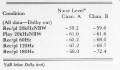
TABLE 1 Noise Level Chan. A Condition Chan. (dB below Dolby level)
Integrex attributes the low frequency interchannel coupling to the common use of Cz and Cis in the encode decode processors. I conducted the remaining instrument and listening tests with the low-pass filter slugs removed.
The record/play frequency response with Dolby encoding/decoding is shown in Fig. 3 as a function of output level.
Tracking differences between the Dolby processors produce significant variations in frequency response. No adjustments are provided for trimming the ''companding law." Variations in the ICs apparently cause the mistracking.
Noise levels, shown in Table 1, fall short of Integrex's typical values. Since hum was clearly visible in the noise, the first three line frequency components were measured separately. Higher power frequency harmonics were negligible. Investigation showed flux leakage from the power transformer caused the hum. Noise measurements made with the transformer removed approximately 3 feet from the chassis were:
------
Tape Play (N.R. off) NBW (N.R. on) (N.R. off) (N.R. on)
70dB (20kHz 74dB
- 66dB
- 68dB
Aux/FM Dolby FM Integrex indicated their measurements were ''CCIR/ARM weighted'' rather than ''unweighted'' as specified in their literature. They promised to notify us when the flux leakage problem is solved.
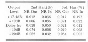
The unit is sensitive to external magnetic fields from transformers, motors, etc. Noise contamination limits the validity of THD measurements at all but extremely high levels. I used a wave analyzer to measure the distortion levels of individual harmonics. Table 2 gives the results at 5kHz. The maximum output level capability (level at which distortion starts to rise rapidly) is plotted against frequency in Fig. 4. The curve confirms Integrex's claim of an 18dB overload margin above Dolby level, at least at mid frequencies. The Dolby processing does limit the output level at high frequencies. Input sensitivity and output levels are sufficiently high so that the Integrex unit should be compatible with nearly all associated equipment.
----------------
-------------------
LISTENING
I performed two types of listening test.
Bypass tests helped determine what audible degradation the encode/decode chain caused as compared to a wire. I also used the unit to audition Dolby-B encoded FM broadcasts and pre recorded tapes.
Fig. 5 shows the equipment used for the bypass test. I adjusted the noise reduction system's gain to equal that of the direct path using the pseudo-noise
TABLE 2
... source. Listening to the noise source, the Integrex unit with Dolby off added a slight midrange honk which made the texture somewhat ''thicker.” The noise source's low frequency thump (= 1Hz) was not quite as distinct. With the Dolby processing switched in, the right channel sounded less bright while the left was somewhat "thicker." Direct-to-disc records were the musical source for the bypass test. The Integrex unit slightly thickened the texture and added some nasality to vocals.
Cymbals were more prominent and loud passages sounded harder. I perceived additional resonances around the individual string plucks of a solo guitar, and noticed some perspective shift with level on wide dynamic range symphonic material. While perceptible, the sonic alteration was less than that caused by some highly regarded preamps tested under similar conditions.
In normal use, the noise level of the Integrex unit is unobtrusive. Barclay Crocker Dolby-encoded prerecorded tapes are virtually silent when decoded through the Integrex. Some of them have a prodigious dynamic range.
Members of our informal listening and beer-drinking group commented on the spacious and stable stereophonic imaging. It's been claimed that a treble cut will acceptably tame undecoded Dolbyized materials; it may make the sound listenable, but for critical listening a decoder is necessary.
After an absence of a few years, WETA-FM in my area recently resumed Dolby encoding their broadcasts.
Their sound quality definitely improved when Dolby transmissions started. I think this was a result of the station backing off on the overall level: this, combined with the reduced preemphasis when Dolby is used, means less limiting and compression of peaks. While Dolbyized broadcasts are billed as being compatible with conventional receivers, a listener without a decoder may be conscious of frequency response variations and perspective shifts with level Perhaps this is the reason Dolby FM broadcasting has not been received with the enthusiasm originally expected. A decoder, such as the Integrex, is needed for maximum enjoyment.
The Integrex noise reduction unit is a creditable and reasonably priced performer; it may also be the only outboard Dolby processor presently available.
However, it does leave sonic finger prints on the music. The market still has room for a state-of-the-art consumer Dolby-B unit.
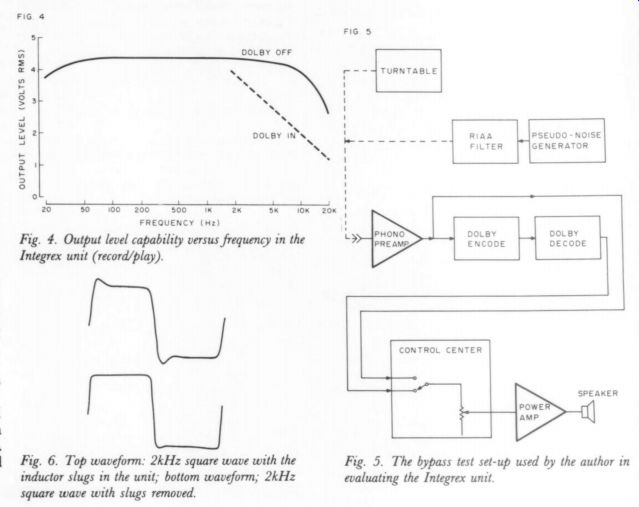
Fig. 4. Output level capability versus frequency in the Integrex unit (record/play).
Fig. 5. The bypass test set-up used by the author in evaluating the Integrex unit
Fig. 6. Top waveform: 2kHz square wave with the inductor slugs in the unit; bottom waveform; 2kHz square wave with slugs removed.
----
Also see:
Test Report: The Jung-White PAT-5/WJ-1A, by David Vorhis.
The Williamson 40/40, Power Amplifier--Return of an improved favorite after a decade