CORRECTION
An error crept into my Figs. 4 and 5, p. 7, issue 3/79. All tube pin designations are transposed. Pins marked 1, 2, and 3 should actually read 6, 7, and 8 respectively. Pins marked 6, 7, and 8 should actually read 1, 2, and 3 respectively. This in no way affects PC patterns, but might add a slight bit of confusion during checkout.
Barry WALDRON; Fairport, NY 14450
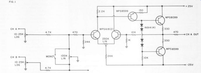
FIG. 1
BANKS PREAMP
IN LOOKING AT THE line amplifier schematic on page 40 of 3/79, I realize there must be an error in the drawing because three apparent faults would prevent the circuit from functioning:
1. There is no bias for the four IN914 diodes
2. The feedback loop has been referenced to the negative supply
3. The ratio of the 18k and 39k resistors does not allow for equitable biasing of the in put transistors.
I offer a corrected/alternate schematic for your readers who may have experienced pro blems. This circuit also includes provision for offset adjustment which allows elimination of the coupling capacitor.
In addition, I've added an alternate Fig. 1 which places the resistors before the balance and mono controls, which reduces the loading on the output of the PSII with the volume control turned up all the way in either the mono mode or with the balance control fully CCW or CW. I hope this helps out with what is otherwise a fine addition to an already excellent product.
NELSON Pass; Threshold Corporation Sacramento, CA 95815
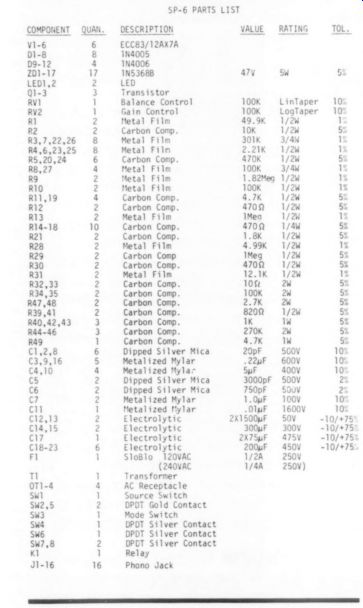
------------ Parts List
OF MARK III'S & MODS SINCE 1 HAVE BEEN USING a pair of Dyna Mk III's to drive my Quad ESL''s for the past 10 years or so, [I've been reading the recent flurry of articles and letters on Mk. III mods with interest and sometimes with amusement. While I've been impressed with the ingenuity and skill that has gone into these re designs, I agree with John W. McConnell's views (TAA 2/79, p. 49) on not modifying these amps and want to add my own two cents worth of advice on the subject.
For best results, I've found, always use the 41) tap (no matter what the stated impedance of the speaker) and adjust the tube bias for minimum distortion, using either a spectrum or a wave analyzer at about 1W output. You can also use a THD meter if you can filter out the low frequency hum components. Using either KT88's or 6550s should give you a definite null and distortion levels of less than 0.05%; if not, try changing the rectifier tube. The most important factor here is using the 4 -ohm tap; while this reduces the maximum available power, you cannot obtain these low levels of distortion from the 8 ohm and 16-ohm taps.
Always keep in mind, when modifying old equipment, that if an obvious and simple improvement can be made to the design, the manufacturer has probably already incorporated it.
I recently tried improving my Gately SM 6A mixer by replacing the 748C IC's with the new 5534's. Comparing these chips' specifications one would expect a vast improvement in performance. Guess again: measurements showed no improvement in noise in the mike input stage or the output driver stage and only a 2.5dB improvement in the mixer stage. The resistors in each amplifier stage, not the IC itself, primarily determine the noise in all these circuits. Keep this in mind if you are thinking about up dating any piece of equipment which uses linear IC's. I left the 5534's in the circuit because they do improve the measurable slew rate, but I can't hear any difference.
CHARLES REPKA; Oakland, NJ 07436
IC POWER
IN USING OP AMP DEVICES with split power supplies, I follow the separate power supply approach favored by several TAA authors.
I use four-pin CB radio mike connectors as power supply connectors. Radio Shack stocks them and so do a lot of small TV repair shops since CB has become so popular. The jack and plug combination is polarized, of course, with a notch. The plug includes a retaining ring that can be twisted tight to prevent disconnection. The four pins are for plus and minus 15 volts, ground, and plus 5 volts, which is handy to power logic I built two of the Jung regulated IC sup plies, put them in separate cabinets, and use one in the lab and one to power my audio system's home-built components. A surplus Scott transformer from Delta provides one CT winding for the split supply and a second 6.3V winding that I run through an IC regulator for the 5V part. The transformer is fully shielded, too (M-9313, 2/$6.00).
JON CLEMENS; Louisville, KY
LIPSHITZ/JUNG FORUM
Beer gets tested more fairly in TV commercials than audio equipment does by the Golden Ear of the underground press. Most audiophiles want guidance from full time reviewers to sort those new components worthy of their personal evaluation from among the large number offered for sale. The moral: responsibility of the reviewer is significant:
More than a six pack of beer is at stake.
Hundreds or thousands of dollars of an audiophile's equipment budget are swayed by reviewers. A beer commercial shows the taster being presented with two cans of beer with the labels covered for a ''blind A-B test. Most audio equipment reviewers, however, use ''open'' tests where influences other than the sound are not controlled. This casual testing has been widely accepted until recently. Now there is a growing body of opinion suggesting that casual testing is inadequate.
It is fine for the audiophile himself to make an ''open'' test because appearance and other non-sonic factors are important to his ultimate satisfaction. If he seeks reviewer guidance however, he has a right to expect unbiased reports of sound quality.
A blind A-B test removes most extraneous influences, however, a significant problem may still exist: The tester or any other person present who knows which component is A and which is B may inadvertently influence the results.
A solution to this problem is the ''Double Blind'' A-B test, in which no one knows which is A and which is B. A convenient method of implementing this test is to have the test ''administered'' by an electrical cir cuit which generates and records a random sequence of A and B for the listener. For each trial the listener is presented with a sound which he identifies as A or B by writing it down. After a number of trials the actual test sequence is revealed and used to score the listener's responses. If he is successful at identifying most A's and B's correctly, it shows that there is an audible difference. He can then, with some confidence, state his preference for A or B. Only then should the components being tested be revealed as A or B.
Statistics should be used to analyze the results. A series of guesses thought to be random may, upon analysis, show that small differences were heard when the data is analyzed. Three out of four correct could easily occur by chance but 12 out of 16 would strongly indicate differences were heard.
Lipshitz, Vanderkooy and Young are of course, proponents of double blind testing.
They emphasize that ''clues'' to the identity of A and B must be carefully controlled. Frequency response of +0.05dB may not be necessary in everyday use, but this degree of matching is necessary in order to compare equipment for subtle qualities such as ''air'', ''grundge'', ''veiling'', etc. Jung, White et al substantially agree with the need for controlling response, level and polarity for fair comparisons.
The present debate is primarily concerned with one statement in the Lipshitz, Vanderkooy, Young letter: ''The audible differences between them (phono preamps) can be exactly accounted for their linear differences (i.e., gain, frequency responses, polarity)..." Jung, White et al believe there are other clearly audible (under proper circumstances) differences. The issue is clear, the implications of the outcome are enormous and a scientific method is available to prove who is right.
It is extremely difficult or impossible to prove that something cannot be heard, however, it can be proven (with double blind A-B testing) that something can be heard. If a difference '""clearly audible'' as the Golden Ears say, proof will not be difficult to obtain, since if a listener identifies unknown A's and B's a statistically significant number 1s as of times (12 out of 16 tries us significant) it indicates he is hearing something.
Our audio club in Detroit, SMWTMS, (South-Western Michigan Woofer and Tweeter Marching Society) has been engaged in controlled double blind tests for the past three years. We have made many refinements in our procedures; at present the test is convenient, fun and exceedingly convincing to the participants. A test runs as follows: Levels are matched to within 0.1dB.
An "ABX'' switch box is used with three switch positions available: one for playing component A, another for component B, and one for an unknown X, which could be either A or B. This allows the closest possible com parison of the unknown to the known A and known B. After each listener decides he knows whether an X is really A or B, he writes his answer along with a comment on sound quality on a form and the box is switched to a '"'new'' X which is also either A or B. A sequence of 16 unknown usually constitutes one t _sting session which has taken as much as three hours.
Extended tests have been tried as well. We have so far been unsuccessful at proving the audibility of small differences. We would like to hear of other double blind experiments in which successful identifications of differences were heard.
Many SMWTMS members wished to have their own double blind ABX box so an inexpensive IC logic version of the original was developed. For $1.00 (to cover copying and postage) a schematic and parts list will be mailed. A report of our tests, a test form, and statistical formula will also be included.
To encourage the use of ABX boxes, we have available boards, kits and complete units.
SMWTMS will also loan ABX boxes to professional reviewers who are willing to document and publish the results of their tests.
In summary:
1.) Audiophiles have a need for, if not a right to, objective reporting of subjective tests by professional reviewers.
2.) The first step toward objectivity is to resolve the debate over audibility of phenomena such as argued by Lipshitz et al and Jung et al.
3.) The double blind test and statistical evaluation can resolve the debate by having anyone score well.
4.) SMWTMS will make the double blind hardware available.
All that is needed now is some individual effort, patience and a spirit of cooperation.
Davip L. CLARK A. B. KREUGER BERNHARD MULLER Davip CARLSTROM
SMWTMS 10155 Lincoln Dr.
Huntington Woods, MI 48070
PAT-5 WJ-A POWERS LEACH THE POWER SUPPLY capacitance modifications suggested by Walt Jung (744 3/79) for preamplifiers makes a striking improvement in the Leach Wide-band preamp (Audio 2/77). 1 added 10,000uF to both the input and output legs of the LM-340T ( +24V) and LM-320T ( -24V) IC regulator, but without the 5uF Mylars. The ''non-subtle sound improvements' are exactly as Jung described: more lifelike and prominent transients, increased and more natural dynamic range, more detailed and stable location and separation, and more open and robust sonic character. For about $40 it's like getting a brand-new preamp!
Rob REES; Bellingham, WA 98225
Walt Jung replies We appreciate Mr. Rees reporting his fin dings about the audible improvements he experienced as a result of our suggestions.
Having others make this experiment in dependently (even on a different preamp), and report similar results with such enthusiasm we feel underscores our message.
We would suggest for safety's sake that Mr. Rees (and others) add the input-output and output-to-common reverse connected IN4002 clamp diodes, when using the extra capacitance. The general scheme is as we have shown for the LM317 (TAA 3/79, figure PS-2, p. 25) and is covered in National's regulator notes. [See also the notes and corrections on the PAT-5-WJ-1A-Ed.]
PAT-5/WJ-1A NOTES AND UPDATES
Mr. Gordon DeWitte writes pointing out, correctly, that the LM317 and 15V zener, in our PAT-5/WJ-1A do not produce 15V. The combination will yield an output 1.25V higher than the zener voltage, as he generally observes. This was a last minute prior to press change, and a clarification note was unfortunately not included.
The +15V busses in the PAT-5/WJ-1A will therefore actually run between 16 and 17 volts, the exact level being dependent upon the particular tolerance of the particular zener and IC used. Note that the ab solute level of these voltages (and their tracking) is not particularly important, but the dynamic stability is very important, in both cases. This is why the "do not substitute" proviso is made for the IN4744A zener.
We'd also like to offer some comments on the use of large electrolytics such as those in the PAT-5/WJ-1A. Some may have wondered why C,;-C; (B) and C,4-Cs (B) are different values, when it appears some common value would be appropriate. It so happens this is true, but the original prototype used units available from surplus stock. C, and C; (B) are selected for minimum ESR, while in C, and C4 (B) ESR is not as critical, but a 30V or higher voltage rating 1s the main issue. In a PA'T-5 these capacitors must be in the can size specified (no larger); in other preamps this may not be as critical, but it helps, to save space.
A common capacitor which will work in any of the PAT-5/WJ-1A's four locations is a 5700uF/30V unit from Sangamo's 500R line. In addition, this unit will most likely work in many other preamp power supply circuits (where it's voltage rating is adequate). If interest is sufficient, Old Colony will make pairs of these capacitors available to the readership, as new computer grades are extremely hard to get.
Some may desire to take advantage of the extra PS capacitance trick, but do not have the room in their PAT-5 for four big cans (because of other mods). While their performance is not equal to the big cans, you can cram four 2200uF/35V axial lead electrolytics on the JW-32 card, in place of the original C,, Cs, C4, Cs. A unit which will fit 1s offered by Rubycon (available from Mouser, PN 20NM905).
When using such large capacitors, it 1s advisable to form them to their operating voltage, particularly if surplus units are used Before using, simply connect a 1k resistor in series, and connect to the voltage source (observing polarity!). Let them sit for 15 minutes or more, or until the resistor's current has dropped to 1mA or less (1V across the resistor). If the current remains high (more than 1-2mA) after 15 or 20 minutes, the capacitor is suspect.
In the PAT-5/WJ-1A mod, we strongly recommend this procedure be implemented with a bench supply before assembly Discharge the caps however (through the 1k resistor) for 10 seconds before you handle and install them.
To speed things up, you can form C2-C5 (B) and C1-C4 (B) in parallel in to voltages of 15V and 25V respectively. Be careful in doing this however, and make sure your connections are secure before In the PAT-5/WJ-1A we also recommend you double check for shorts, before you first power up.
Tack a 100 ohm 1-W resistor temporarily in place of the line fuse supplying voltage power up , and apply power. Allow 15 minutes for stabilization, after which the voltage drop across this resistor should be about 5 volts AC. This resistor also allows a 'soft start limited turn-on surge, and allows the ipacitors o fully form. When all is well remove th resistor and re-install the line powering down.
Allied to the above are the optimum grounding po capacitors. It has also be PC34 ground terminal [...] ( I better performance thar chassis ground. Therefore re that the two bypass s be PC-34 grounds (one ground wire from this pe [...] should be heavy gauge stranded. Al solder this wire to the put jacks. [...] preferably
The jacks on the back panel hay been wired in 'daisy chain' fashion insofar as their grounds are concerned, and this is retained. However, to prevent the necessity of requiring ground return currents to the power supply to flow through chassis ground lugs (and their poorly defined contact sui faces), a heavy gauge stranded wire should be run from one of the gold output jacks back to the common ground on the added filter caps, C,-B and Cs-B. Make sure wire is soldered securely, at both ends.
WJ
-----------
LIPSHITZ/JUNG FORUM
I was GREATLY disturbed by the recent exchange of letters by Lipshitz, Jung, White, Moncrieff, Curl etc. published in Issue 3, 1979 of The Audio Amateur. I'm disturbed because it appears that Audio Amateur has decided to enter the Realm of the Audio Mystics, that wondrous Kingdom with its Magic Speaker Wires and Golden Eared Gurus who can hear what no other mortal can. I hope this isn't so for TAA was one of my last remaining sources of sanity and common sense.
But to come to the point. Both Mr. Lipshitz and Mr. Jung are highly regarded in the audio field and I respect both of their opinions, but they are treading on treacherous ground when they make judgments based on subjective tests that cannot be verified by other means. It has been a long established procedure in other scientific disciplines to not accept the results of experimental data until those results have been duplicated in dependently. This is done to minimize the chance of possible errors and personal bias.
The fact that Mr. Jung and Mr. Lipshitz did not arrive at identical (with respect to the sound quality of a particular capacitor) means that there are errors in either Mr. Jung's test or Mr. Lipshitz's or both. Several possibilities for where errors conclusions could have occurred come to mind. Did Mr. Jung and Mr. Lipshitz listen to identical loudspeakers in with identical acoustical properties? Were identical power amps used as well as preamps, phono cartridges and turntables: rooms ) Was identical pro gram material (records or tape) used and played back at identical levels? Were the capacitors in question installed in the same manner? If any of the above is not true for their then the results are not valid. They did not perform the same test.
May I also suggest that Mr. Lipshitz and Mr. Jung (and all the other correspondents in this debate) read Neill Muncy's guest editorial In 1979 of TAA. To paraphrase Mr. Muncy, most commercial recordings have distortion levels that tests, valid Issue 1, are many orders of magnitude greater that the levels considered intolerable for even average audio equipment. Even the best Direct Discs are subject to the distortion generated by microphones, consoles, recording cutting heads and their associated power amps, as well as (more importantly) the distortions generated by groove geometry, groove and the interactions with the playback stylus size, shape and mass (the latter is independent of the cartridge being of the moving coil or fixed coil type).
Also to be considered are the distortions (or colorations) generated purely by the location of the microphones and acoustical environment of the recording. Enormous changes can be made in the recorded sound (to which one can apply the current Buzz Words such as Depth, Apparent Dynamic Range, Transparency, etc., etc.) simply by moving the microphone(s) a foot or so, or by changing its polar pattern or by changing the acoustical environment.
With all these variables mucking up the recorded signal, to blame subtle, subjective effects on the lowly polar capacitor strikes me as a perfect example of ''Not seeing the forest because of the trees." If Mr. Jung did hear a difference when polar capacitors were used in his preamp, to say that it sounds better or worse 1s only his opinion until the other variables have been removed and his results duplicated by others. And in view of other letters on the subject (Marsh, Pass, 7A4A4 2/79) and not having the opportunity to build and test Mr. Jung's circuit for myself, it is possible what Mr. Jung heard was the device (the capacitor) being improperly used in the circuit, a trick engineers have been doing for generations.
While Mr. Lipshitz's conclusion concerning audible differences in preamps and their relation to frequency response was possibly in error because of too small a sample, I found Mr. Moncrieff's resulting lecture on logic to be a bit sophomoric. His discussion concerning the results of a hypothetical test of all possible combinations of preamps is perfectly correct from a purely logical point of view, but it doesn't make much common sense. And I find his suggestion that ten or so of the Self Appointed, Golden Eared, Chosen Few should retreat to the Mountain Top and there, after Secret Studies into Mystic Arts of Audio, make pronouncements of Truth to the Masses to be a bit presumuous.
What should be done instead is to have a totally open exchange of ideas and thoughts.
When an experimenter comes across some thing he feels is significant, he should imediately publish the results along with complete details of the experiment so that others can verify the results. There should be no embarrassment or accusations made if the results are not duplicated but rather serious inquiry into the cause of the differences.
Subjective comparison tests can give valid results but only if the tests are double blind, conditions are carefully controlled and a statistically significant number of tests are made. A good example of this is the amplifier listening comparison tests (tube vs. transistor) conducted by Acoustical Manufacturing Co. (QUAD) in England. A description of the tests and their results were published in a recent issue of Hi Fi News and Record Review, Nov. 1978, and Wireless World, July, 1978. Perhaps the Editor could reprint that article for us in 7AA and since contributing editor Reg Williamson was one of the listening panel members, he could provide additional details and insight into the tests.
This letter has rambled on far too long, but 1 would like to close with one additional thought that no one else seems to have brought up. It may indeed be possible that some of the subtle effects we have been arguing about truly do exist and are audible, but only to a statistically small part of the population. There really may be such a thing as Golden Ear, but you have little choice in the matter since it may be caused by a recessive gene, Now, with all of that oft my chest, I'm going to sit down and listen to some music and will enjoy the experience in spite of the fact that my moving magnet cartridge has inadequate bandwidth, my power amps suffer from excessive TIM and my loudspeakers lack depth and transparency.
CHARLES P. REPKA; Oakland, NJ 07436
Walt Jung replies:
Mr. Repka's letter 1s almost exactly the type anticipated in our article on the PAT-5/WJ-1A mod (TAA 3/79, p.24 & 26)
I am disappointed that he feels Dave White and I have done nothing to independently corroborate our statements on capacitors We have sent out samples of this preamp tor critical review (see this issue p. 48), in these pages as well as others, which we trust will appear in time We believe independent review by a number of neutral people to be the only real route to an answer to the controversy, and this will take time We urge Mr. Repka to watch these pages and see how the Critics and readers respond to these issues. The Rees letter, above, is an example SERVOS, SLEW, AND EQUALIZATION In reading Walt Jung and David White's piece in TAA 3/79, it was a great pleasure to see someone else agree with what we have found to be so important. May I make a few comments, and then share some further ideas?
1. On capacitors, and eliminating them. Seeing Jung's servo control was a big shock. I made almost exactly the same circuit a few Jung, but months ago, while we were trying to climinate the effects of capacitors, and couldn't tolerate the DC offsets due to simply direct coupling. At first we liked it very much, but then we did some careful listening tests. (Jack Carlson, one of my audio colleagues in Pennsylvania, was responsible for starting this). We found we could hear its presence, and that one large mylar bypassed by a mica has less effect used as a DC blocking capacitor. It is possible that we were not using a high enough quality capacitor in the servo circuit, or too short a time constant, but I am not sure this explains the effect. In any case this circuit can certainly be worse than blocking capacitors if it is not done properly.
2. This next statement may bother Walt nonetheless, I think he can demonstrate it too. The slew rate of a phono preamplifier can be extremely low, less than one volt/microsec., and the quality still be extremely high. In fact the best one I know of has a slew rate at that level. I am not saying that the slew rate of the amplifiers in the circuit can be low; this certainly is not true Various people have suggested, usually in reference to tube circuits, that the equalization should be done between stages rather than in feedback loops around stages. I have never seen a good explanation of why this should be so.
Nevertheless Jack Carlson tried this with op amps and reports it takes three op amps to do this properly. He told me over the phone that it was a quite significant Improvement; I didn't believe him but when I was up in Pennsylvania in May we did some very thorough tests comparing the sound of circuits with three op amps using various combinations of feedback and **passive'" equalization. Much to my surprise, the results are that for best results all the equalization must be done with resistors and capacitors between stages Equalization within the feedback loop does not sound as good. In the 'passive' e.q. circuit, the gain is best split equally between the three stages, which means that the circuit will have a very low slew rate. It will not produce a sine wave at 20kHz at high levels, yet it is the best.
Maybe others have experimented with this; if not I hope they will.
3. I notice that Jung-White use series resistors at their outputs.
Is this just to assure stability, or do they have a very specific reason for it? We did some tests on op amp loading in January. I was pleased to find that a good op amp can be loaded with much less than 1k) with only minor loss in fidelity, and that anything greater than 3k is inaudible to us. On the other hand, 100 picofarads of good capacitance causes a quite noticeable loss in fidelity. Have others noticed this, and do you have any idea why? Maybe this has some relationship with the effect of using passive e.q. although capacitors in the feed back loop act like capacitive loading on the output only for error signals generated within the loop, that is, the noise of the amplifier at very high frequencies. I have no explanation for these two effects (2., 3.) Hope these comments are useful. If readers have any ideas which would benefit from independent verification, or perhaps Just another viewpoint, please send them along. We are all working on a very interesting thing.
MIKE SULZER Arecibo, Puerto Rico 00612
GREENHILL AND EQUIPMENT EVALUATION
Your letter about Dr. Greenhill's article (TAA 1/79, p. 17) arrived late but I would like to comment in general about several aspects of the article without making any detailed criticism.
1. Moncrieff's M rule. If the statement at the top of your Section 2 (p- 18, col. 2) ap plied it would be impossible for almost all reviewers to compare amplifiers in the top class, for all of them have distortions that are far, far lower than those in record players, tape decks, or any of the signal sources that reviewers must use
2. There must be some misprint in Box B, p. 19 for it is almost impossible for a room to have a reverberation time of 50ms and 1t would be a very poor listening environment if it could be achieved. An RT of 500ms is more reasonable.
3. Surely there is only one way to accurately evaluate equipment of the highest class. One compares the results of subjective comparisons with the results of objective measurements and if there is any significant difference the explanation is investigated. In the overwhelming number of situations any subjectively judged result has an objective explanation if the right tests are carried out.
There are very few situations where objective and subjective opinion are in unexplainable conflict. Objective data or subjective opinion in isolation are of little value.
(a) I suggest that the real problem in reviewing equipment is the reviewers who have sufficient experience to shortage of allow them to reach an accurate judgment of sonic quality and sufficient engineering knowledge and test equipment to obtain and interpret the data acoustic tests. Reviewers who are musically obtained by electro based deny the importance of measured data, while reviewers who have inadequate experience of musical performance place un justified reliance on electro-acoustic data.
4. We now have about twenty-five years experience in evaluating equipment and during that time we have used at least a dozen different types of panel presentation. When a proper statistical control is used there are no very significant advantages in the accuracy of several others, but there is one method that leaves each member of the panel convinced that he one method of presentation over has given the right answer. This involves allowing each panel member to listen to the equipment by himself for as long as he likes.
His notes are then studied by another judge and compared with the similar notes made by each of the other panel members. Any significant differences are explored and eliminated by another check. There are many procedures that should not be used but discussion of these would require more time than is available at the moment.
James Moir James Moir Associates
Chipperfield, Herts England
LZ-1 VS. HAFLER & INVERSION WITH REFERENCE TO David Vorhis' comments (74AA4 1/79, p. 15, bottom of column 2) that the Lampton-Zukauckas preamp's high level stage resulted in a 'slightly softer, more diffuse sound'', I would like to point out that, as this stage is polarity-inverting, the change is precisely what I would have expected when it was auditioned. (See my letters in TAA 3/78, pp. 48-49 and 2/79, pp. 52-54.) Since the Hafler preamp is non inverting, it will not sound identical to the LZ-1 even if its RIAA equalization and input impedance are similar. Of course, since the LZ-1's tone control stage is always in circuit, its polarity inversion is immaterial in practice (there is no polarity standard for records) and can be changed by reversing the loudspeaker leads if necessary. But polarity must be taken into account when comparing two components. (Note that some preamps change their polarity when their tone controls are switched in, thus automatically guaranteeing on accompanying change in sound quality!)
S. P. Lipshitz Waterloo, Ontario, Canada
ELECTROSTATIC ENTHUSIAST INSTRUCTING THE EQUIVALENT of a factory ouilt electrostatic speaker selling for between $2,000 and $6,000 is a mind-boggling thought; however, I accomplished just that last year. The publication of David Hermeyer's first project (744 3/72, p. 11) brought closer to reality the far-out whim that a person with 10 thumbs might just pull off such a feat; but not until I read Roger Sander's article (744 4/75, p. 18) did my aspiration to such a spectacular system become more or less plausible.
Upon studying the two very different designs I developed a burning desire to em bark on a plan incorporating the best of both concepts. The result is truly fantastic! I need-
Lettersed several attempts before overcoming some faults in my design and construction techni ques; indeed, three or four times I thought of giving up, but with each failure came help and inspiration.
I live near Roger Sanders, so on several occasions I was able to listen to his outstan ding stereo. This provided a kind of natural high and a renewal of hope that with just a bit more work I'd have a comparable pro duct. In addition to these periodic listening sessions, Roger and two other people frequently provided assistance; without their untiring work this project would not be the success it is.
I here thank Roger for the advice he gave me in person and in our many long phone conversations. My thanks and appreciation to also to two others. Dr. Bill Mekeel pros 1ded advice, labor, and tools; his unselfish efforts greatly eased the construction work. Ed ward Smith's engineering and technical prowess enabled the project's inception, incubation, and final relatively painless delivery in to the world.
Finally special thanks are due to Dave Hermeyer: were it not for his initial interest and efforts this and the many other electrostatic speakers built over the past years would not have given us audio amateurs and audiophiles there many hours of enjoyment.
My system consists of an enclosure approximately 37" x 55" x 13" with a 10 sq. ft. radiating area. I arranged 10, 6” x 24" panels in an arc for a dispersion of 35 degrees. The speaker is powered by an 8068 Class A amplifier, updated to include modifications approved by Roger. Although the panels are equalized flat to 165Hz, I used an Old Colony crossover at 480Hz to two Speakerlab folded corner horns powered by a Pass A-40 amplifier.
The unanimous opinion of all who have heard my system is that it beats all commercial electrostatics for accuracy, smoothness, and detail.
If you are contemplating building a speaker system I urge you to give the esl serious consideration. It does require more time and effort than the usual project but the results are far and away superior to the ordinary homebuilt, not to mention factory built designs.
As construction of an esl and amp can at times be difficult, I would like to start a correspondence clearinghouse made up of interested people who have successfully completed an esl project and are willing to offer their knowledge and construction hints to others. If you would like to participate in this venture please drop a note to me. My own assistance is available to those who would like to begin constructing an electrostatic speaker system; in addition, if you are within com muting distance of the Stockton-Sacramento area, I'll be glad to have you come hear my speakers.
BARRY A. WALDRON; 8811 Little Oaks Way Stockton, CA 95207
ELECTROSTATIC CUES
AS I WORKED on my electrostatic speaker system I noticed an ungrounded "scope probe was picking up the audio signal from the panels. I placed the probe about two inches from the panels while testing, though on my Tektronix 465 'scope I can display signals three feet from the panels. Using a 'scope probe in this way you can troubleshoot the high voltage sections of direct-coupled amplifiers without fear of blowing the scope inputs. I found my ESA-3 amplifier (Dave Hermeyer's design-7A44 3/77, p. 8) was oscillating at 1 MHz because I had changed op amps.
Take warning: carefully shield your amplifier and keep it away from your speakers. Because the feedback circuits of these amplifiers are high impedance, this separation will keep the speakers from coupling back to the amplifier. As a side note, put a neon bulb close to your panels. In a dark room: you can watch it light up on loud passages. (My thanks to Jim Strickland of Acoustat for this information.) The Hermeyer ESA-3 is a terrific amplifier when direct-coupled to a set of RTR ES6 tweeters. (Please note this change is not authorized by RTR and invalidates your warranty.) The ESA-3 will put out 8-10dB more spl than the recommended 60W amplifier. As to sound quality I had on ly a mediocre solid state amp but the improvement was most impressive. Also, since each speaker has approximately 900uF and the ESA-3 was designed for a 3300uF load, the power bandwidth is increased to about 10kHz.
I crossed over to the RTR panels at 5kHz.
This seems the best compromise, although I plan to experiment with different crossover frequencies and slopes. I don't recommend going much lower than 4kHz with the RTRs.
Those of you using dynamic woofers with ELS midrange and tweeter panels will be interested to know that the woofers acoustically couple to the ELS panels. You can demonstrate this by turning off the midrange amp and sweeping an oscillator into the bass amp. The panels resonate as they are excited by the woofers. If your ELS panels are on top of your woofers as mine are, be sure to isolate them from the woofer panel vibrations with elastomeric mounts or supports.
David M. WHITE, Jr.
Nashua NH 03060
ESL-CONSTRUCTION POINTS
I WOULD LIKE TO ASK Mr. Hermeyer a few questions about his speaker system Concerning panel construction:
1) Should the graphite side of the diaphragm face the front or rear panel, or does it matter?
2) Dust cover-do they add to or subtract from sonic qualities? I'm thinking here in terms of the additional moving mass which they couple to the diaphragm.
3) Wouldn't too much tension in the dust covers tend to dampen frequency response and transient response?
4) Wouldn't grille cloths or foam be sufficient to keep the panels free from contamination?
Concerning panel response:
Letters
1) Is the dip in response centered at I0KHz a result of diaphragm and/or dust cover tension?
2) Would different tension shift this dip up or down the spectrum?
3) Could this dip be caused by the higher % of distortion in the amp at 10KHz? Or-
4) Could the higher % of distortion in the amp be caused by the panel response at 10KHz? Concerning the power amp
1) Why were distortion measurements taken using a 2500pF load rather than the nominal speaker load of 3300pF?
2) Can this amp be used direct coupled to OEM panels with good results? As you can probably tell by the last question, I am somewhat hesitant to build my own panels while there are still many variables to contend with. Perhaps a tension testing device of some sort, standardized, would be of help, allowing the home constructor to more closely duplicate your results and achieve better panel-to-panel uniformity.
SEAN COLLINS Moscow, ID 83843
Mr. Hermeyer replies:
Panel construction
1) The graphite side of the diaphragm can face the front or rear equally well. Another reader, David White, says that the THD will be lower if you coat both sides of the diaphragm. Perhaps, but I am unconvinced I haven't tested that idea
2) The dust covers have almost no effect on he p: I 'rto anc mass adds to th mast of the diaphragm nd low yy ashe ' cutoff frequency. But even with dust covers the response extends to 30kHz.
3) About tension: The diaphras S 1 S- a 4 -- fairly high tension, and that (plus other factors) limits the bass response. For midrange and high frequencies the tension has no effect on the frequency response or transient response. The dust covers have very low tension-just enough to remove wrinkles for ap pearance sake. The low tension does not significantly limit the bass performance
4) Grille cloth is not sufficient to kee p all dust out. Grille cloth also has a cutoff frequency de 4 sheoention at d 15 to 20kH eno' ho i hat ds g REN oo: FHP. LC 1 SheWh Deacon chose not to use ny grille cloth on my speakers. Foam probably would be sufficient to keep the dust out, but it ruins transient response. Of course, these effects apply to all speakers. If you have a good microphone, it would be very interesting to test a few speakers with and witl leis arville cloth or
3) I don't know what causes the slight dip in response, but it is most likely mechanical in yrigin ; »SONANce o S Or 0 A JETS: SA § Shah of Wh plivias or of si came m- a a Panel response
1) and 2) see above the frame. It is not in any way related to the amplifier.
4) The distortion in the amplifier at high frequencies is not caused by the panel response dip at 1]kHz. The distortion increases monotonically with frequency for two reasons. First, the open loop response of the amplifier drops at a high frequencies, and so there is less feedback there. Second, at high frequencies and high level the amplifier current clips when driving its rated load. Note that with no load the distortion is much lower. This is normal.
Power amplifier
1) The distortion measurements were made with a 2,500pF capacitor as a load. I used 2,500pF because I had one handy. Also, the amplifier can be used to drive either more or less capacitance. I am presently driving 20 panels (6,600pF) from each channel.
3,300pF is a somewhat arbitrary choice for the load ''rating."
2) My amplifier can be used with other types of electrostatic speakers, either home made or commercial if and only if: 1) The voltage the speaker requires is compatible with my amplifier (2,400 volts peak to peak between the two plates), and 2) the capacitance is approximately right. The speaker may be damaged if it cannot withstand the peak voltage my amplifier supplies. And the speaker will not put out full volume if it re quires a much higher voltage than my amplifier. And needless to say, you must disconnect all stepup transformers, crossover networks, and AC powered bias supplies.
QUIET PREAMP POWER
MY NEW POWER SUPPLY DESIGN is for a tracking regulator whose (+) and (-) output is changed via a single zener diode. It's a syn thesis of Jack Hazlehurst's supply (744, 4/73, p. 17) and ideas from National Semiconductor's voltage regulator hand book.
Noise is 2000V @ 100mA I;. Regulation is < .25% (I'm not sure of the exact figures because I haven't made accurate measurements.) The FETs reduce noise by a factor of
10. Any FET with I, = 2mA and VBps =
30V will do. It's a great circuit for low noise preamps.
RE YOUR EDITORIAL in 3/78:
I don't care how many advertisers you have or who they are, just so long as you keep the articles and philosophy the same. But don't do equipment reviews at all.
Phase inversion is audible to me and at least three audiophile friends (See Stanley Lipchitz’s letter on the Jung/White PAT-5 modification, 3/78, p. 48). The explanation is that we are used to hearing the initial wavefront as a pressure on the eardrum. If we heard instead, for example, a kick drum beat as a rarefaction (speaker cone first moving inward) we would think it unnatural.
Research has also shown the hearing mechanism is more sensitive to negative pressures than to positive pressure displacements.
So, although the reasons Walt Jung gives for inverting configuration are justified from the narrower perspective of a phono stage, the design is fundamentally wrong as viewed from an overall systems approach taking hearing processes into account.
Of course, the cure is simple: invert the phono leads. The point should have been made in the original article, though, not in letters about it.
I personally think the phase reversal is a more serious problem than a couple of 0.01dBs or 0.001 THDs. Actually, what the world needs is not more preamps, but a real ly good power amplifier.
R.M. Marsh Livermore CA 94550
------------
------------------------
Also see:
The Williamson 40/40, Power Amplifier--Return of an improved favorite after a decade