A Power Meter---LEDs give better peak power clues than a needle in motion
by Duncan W. MACARTHUR
This peak-reading constructional project uses light emitting diodes as fast indicators of amplifier power level.
BY NOW MOST OF US have realized the output meters so commonly found on power amps are nearly useless for measuring music signals; the meter nee dle cannot move fast enough to keep up with the peaks in the signal. Even expensive peak reading meters are often unclear about what a given meter reading corresponds to in terms of actual power output.
The LED power meter can react almost instantaneously to an input signal and displays the result clearly and unambiguously. I designed the prototype for use with a 60 watt (avg)/channel amplifier; it has 12 indicators ranging from + 3dB to -30dB in 3dB steps. You can easily modify the 0dB level and change the number of steps and step size if you wish.
DESIGN
For analysis we can divide the circuit in to three blocks: an analog input and switching section, a digital logic and display section, and a power supply.
IC, lowers the input voltage from the power amp to a level compatible with the rest of the circuit: 2.20 volts output corresponds to a + 3dB reading. Since this is a voltage-measuring device,. the power will depend on the associated speaker system's impedance. The values I give for R6 and R7 are for 4-ohm (120W = 22.0V) and 8-ohm (120W = 31V). The rest of the input circuit is a precision full wave rectifier from Walt Jung's IC Op Amp Cookbook, which gives a positive only output to drive the meter's digital section.
R15 to R35 comprise a voltage divider. With the reference 5.2 volts applied, we adjust Rs so that the test point (between R16 and R17) is at 2.20 volts. Since we want 3dB steps (in power), each successive resistor divides this voltage by a factor of √2. We then compare this series of reference voltages (in IC4, IC5 and IC6) with the voltage output from the first section. Whenever this voltage rises above a given reference voltage, the comparator switches, turning on the associated LED. The LM399's current output capability is marginal for driving LED's directly, so we use a pair of Hex inverters to drive them. I prefer the 74H04 to the 7404 as it can sink more current. With the 2008 current limiting resistors specified the LED's run fairly brightly so they are easier to read under adverse conditions.
The circuit's power supply can be quite simple. Reasonable amounts of ripple will not affect its operation, with the exception of the 5.2 volt reference which should be well isolated from the other supplies.
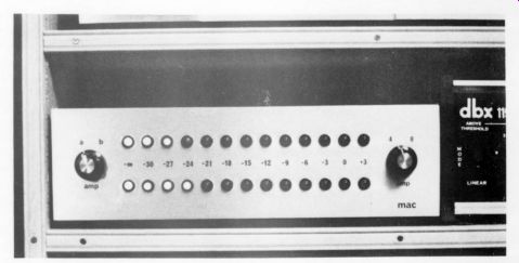
Fig. 1. Front panel view of the LED Peak Power Meter with switches set
for amplifier A whose output impedance is 4 ohms.
CONSTRUCTION
Although you could build this circuit on a piece of perforated board, 1 recom mend that you use an etched circuit board, mounting all parts on the board except the switches and readout LEDs.
First build the power supply section T1, D1-D5, C1-C6, C8-C11, R1, R2, R4, IC9). IC9 must be mounted on a heat sink; in the prototype I used a U-shaped piece of black aluminum with two 2" x 1.5" fins. After mounting these, temporarily connect the power cord to T1.
Check all four voltages. You should get two at about +5 volts and the other two at +8 volts or so; don't worry if the last two are a bit off.
After you've checked out the power supply, wire the rest of the board. If you don't want switchable impedances, you can use only one of resistor R6 or R7 and wire a jumper in place of S2: Use sockets for IC1, IC2, and IC3, as you may need to replace these. Observe the correct orientation of all diodes, electrolytic capacitors, and ICs.
The PC board has foil on both sides.
You should solder all components (except the integrated circuits) to both sides where foil pads are available. The ICs need only be soldered to the reverse side of the board. A number of feed-through connections connect the two sides of the board. Insert a short piece of wire through these and solder on both sides.
If your power meter doesn't work correctly, check to make sure all components are soldered on both sides.
Mount the LEDs in an aluminum front panel. The best way is by using plastic clips in 17/64" holes. Arrange the holes in horizontal lines, vertical lines, meter-shaped arcs, or whatever else looks good to you. Our suggested panel is diagrammed in Fig. 6.
You can connect the LED power meter to any amplifier with a common ground between its outputs (check with a schematic or the manufacturer if you're not sure). Dg protects the digital circuitry from overvoltages, but you might possibly damage the input stages if you apply a signal greater than (Rs/R6 x 5 volts).
If you use S1 and S2, make sure you get the correct types of switches. S1 must be a BBM (break before make) type: if you use another, you will connect the outputs of the two amplifiers together.
S2 should be MBB (make before break) type so IC, does not generate large transients on switching. (Note: due to changes in design, Rs; and Dg do not exist.)
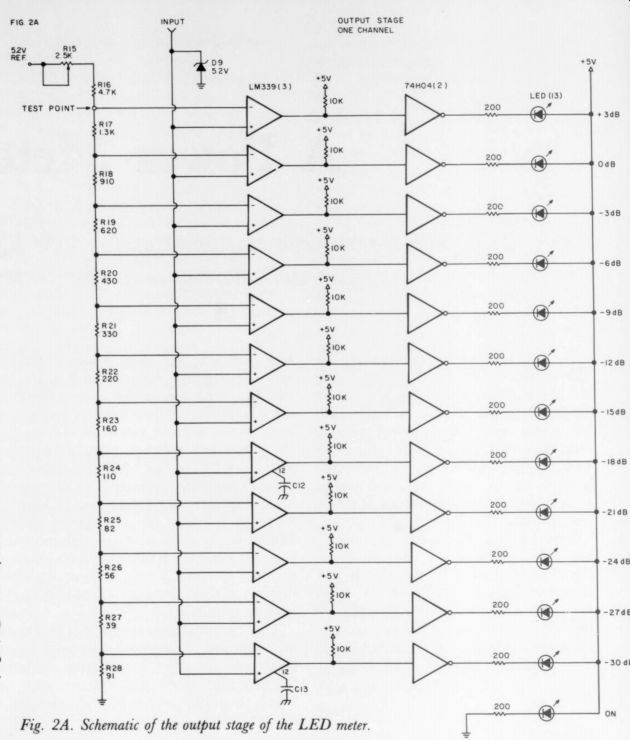
Fig. 2A. Schematic of the output stage of the LED meter.
-----------------
PARTS LIST
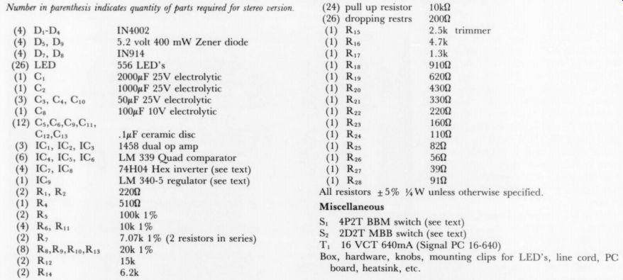
trimmer (1) CGC; 1000uF 25V electrolytic (1) R: 4300 (3) Cs, Cy, Coo 50uF 25V electrolytic (1) R: 3300 (1) Cs 100uF 10V electrolytic (1) Ra 2200 (12) Cs,Cs,Co,Cu1, (1) Ra 1600 Ci2,Cis .1puF ceramic disc (1) R: 1109
3) IC,, IC,, IC, 1458 dual op amp (1) Ra: 820 (6) IC, ICs, IC, LM 339 Quad comparator (1) Ry 562 (4) IC, ICs 74H04 Hex inverter (see text) (1) "Ry 39 -ohm (1) IG, LM 340-5 regulator (see text) (1) R: 91 -ohm (2) Ry, Ry 2200 All resistors +5% %W unless otherwise specified (1) 5100 (2) Rs 100k 1% .
(4) 10k 1% S; 4P2T BBM switch (see text) (2) R; 7.07k 1% (2 resistors in series) Sz ged - pe a _- (8) Ro.R,0.R,. 20k 1% I'' 16 VCT 640mA (Signal PC 16-640) (2) 15k Box, hardware, knobs, mounting clips for LED's, line cord, PC (2) 6.2k board, heatsink, etc.
Miscellaneous
-----------------
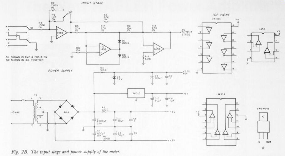
Fig. 2B
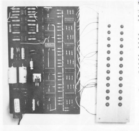
Fig. 5 [...] The 2-sided circuit contains the meter circuitry except the LEDs and switching (not yet installed on this early prototype). The regulator heatsink can be a simple piece of bent aluminum 1.5" x2" 1/16".
--------
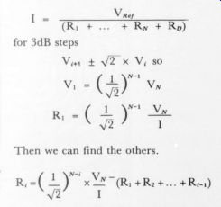
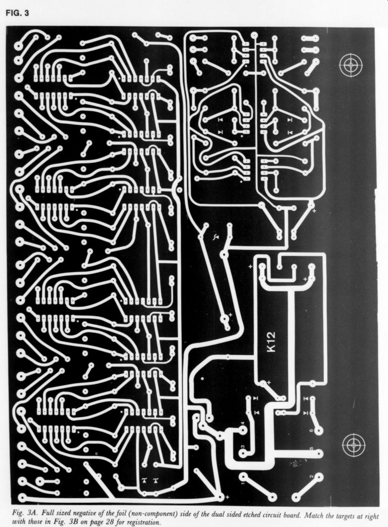
Fig. 3A
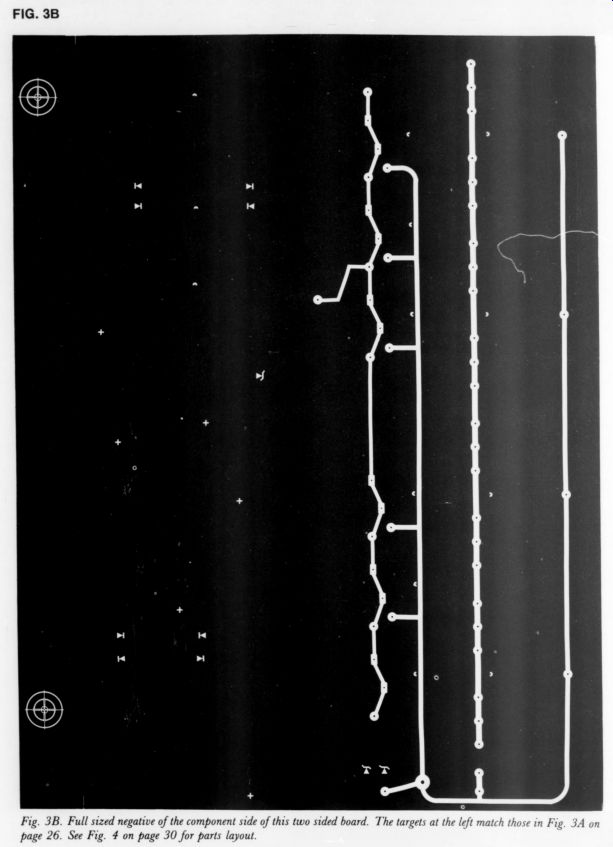
Fig. 3B
----------
MODIFICATIONS
To change the 0dB power level or the speaker impedance, all you need do is adjust R5, R6, and R7.
R5/R6 =
where ( +3dB pwr) is the desired full scale power, and Z, is the nominal speaker impedance. (Note: Rs/R; is determined by the same equation.) If 1% resistors aren't available, you can substitute a small trimmer potentiometer. Changing the step size or number of steps is a bit more difficult. If we analyze the voltage divider, we the following results:
Then we can find the others.
To change the number of steps, pick a total R (say 10k), deter mine N and V_N, and then calculate the resistance values.
If you want to change the step size you have to adjust the relationship between V_i+1, and V (i.e., for 6dB steps V_i+1 = 2V)).
All this is best done on a computer if you have access to one.
I will consider reasonable re quests for other calculations.
FINAL THOUGHTS
My unit is quite accurate although I used 5% resistors in the dividing network. If you set the 0dB point exactly, -30dB is within 1dB of correct. The two channels match very well due to the use of 1% resistors in the input and a single reference voltage chain. If you have problems with balance on low power readings, try switching around the three input ICs; imperfections in these and in D; and Ds can cause problems.
On my unit all the LED's light briefly at turn-on: I believe this is due to the power supply charging. At any rate, it doesn't seem to have any bad effects.
This meter is more 'active' than you may be used to. It follows the signal so exactly that peak detection is limited only by your eyes' ability to see the short flashes. I feel it gives a good idea of the instantaneous power output. 0 This meter is more
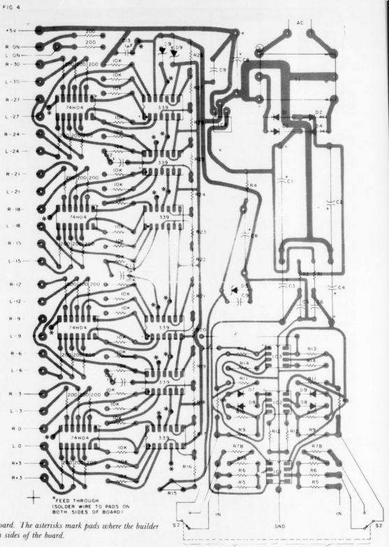
Fig. 4: Parts location the the PCB/ The * mark point where the builder must solder feed-through wires to both sided of board.
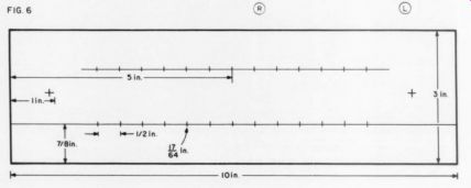
Fig. 6. Suggested front panel layout dimensions
ABOUT THE AUTHOR
Duncan McArthur is a graduate student in Nuclear Physics at Princeton University. In addition to his studies he builds and troubleshoots computer interface electronics. He and his wife Nancy both enjoy listening to music which has encouraged the design and construction of many pieces of audio equipment.
----
Also see:
The Williamson 40/40, Power Amplifier--Return of an improved favorite after a decade
Location Recording Basics, by William F. Ruck, Jr.