New light and hardware for the phono curve's basic shape.
by STANLEY P. LIPSHITZ and WALT JUNG
READERS WILL BE AWARE of the recent correspondence between the two authors regarding RIAA equalization in phono preamplifiers [1,2]. This has led to a re-examination of many familiar circuits, and has shown the need for changes and corrections to many of these in order to improve their accuracy. Extremely high accuracy can indeed be achieved by careful design, such as in the Jung-White modification of the Dynaco PAT-53 , and many readers may be interested in having available an inverse RIAA circuit of sufficient precision to enable them to measure the deviations of phono preamplifiers to a high order of accuracy, as well as to con duct critical listening tests.
TAA published in 1971 [4] an inverse RIAA design by Reg Williamson, shown in Fig. 1. In original form this circuit is fairly accurate, and indeed is suitable for many requirements. However, it can be improved by changing R1 from 910k to the theoretically ideal 883.333k, or 887k ( nearest 1% value). But, even then the termination resistor R3 slightly displaces the middle RIAA time constant T2 (ideally 318-uS) from its desired value, because of the way in which the component values interact in determining the circuit's overall time constants. For a complete theoretical analysis of this see "On RIAA Equalization Networks", copies of which are available, free of charge (while the supply lasts), from the first author at Dept. of Applied Mathematics, University of Waterloo, Waterloo, Ontario, N2L 3G1, Canada.
Ideally the frequency response of an in verse RIAA network should be as in Fig. 2.
The corner at f4 should not occur at all (i.e. f4 = infinity Hz); in practice it is unavoidable. In general it should be placed as high in frequency as possible, so as to minimize deviations occurring in the audio frequency range of interest, namely to above 20kHz.
In considering an improved inverse RIAA circuit, taking into account all significant interactions (e.g., the effect of R3 and driving source impedance), we originally felt that an active pre-emphasis circuit might be necessary. Such a design, unfortunately, introduces as many problems as it circumvents. It was then decided that a slight modification to the Williamson circuit would be most practical. The circuit is shown in Fig. 3. Pre sent owners of previously purchased Old Colony Williamson networks can easily adapt them to the new values, if they so desire.
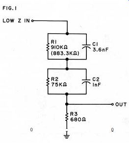
Fig. 1. The original Reg Williamson circuit and its modification.
You will appreciate just how good this network really is if you examine the data in Table 1, which lists the relative ac curacy of two of these networks for various test conditions. For some time Old Colony has been supplying the Williamson network with an ideal R 1 value of 883.3k and all 1% circuit components, as shown here. In the first column shown (listed as stock), this version of the network can be seen to offer better than ±0.1dB accuracy, with sample number 1 being appreciably better (due to values which fall closer to theoretical).
These measurements were taken with a 600 ohm load resistor, the kit value sup plied for R3. However, as noted above, the presence of R3 not only places f [4] at 338kHz: it also alters mid-band response.
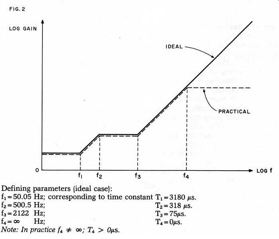
Fig. 2. The frequency response of an inverse RIAA network
in ideal and practical cases.
Fortunately, the mid-band error can be compensated for rather easily by minor adjustment of two network values, R2 and C2 being convenient for this purpose (as described ins).
With an R3 termination resistance of 600 ohms, R2 and C2 should be altered by shunting with the R2 ' and C2' values ( noted as dotted). This yields the (compensated) responses shown in the R2 ', C2 ' columns for the two sample networks. As you can easily note, this version is much better for either case over the entire band.
In both, the response drops above 20kHz, due to R3 . Network #1's accuracy is notable, and network #2 is just in excess of + 0.05dB.
The result of a source resistance Rs of 300 ohms is shown in the third columns, and results in some deterioration. Notice that here the high frequency (hf) rolloff begins at a lower frequency (as expected), and also that mid-band response is not as even. The latter problem is because R2 ' and C2 ' are not the optimum value for this source resistance, having been calculated for only the R3 = 600 ohm resistance. The corresponding values of R2 ' and C2 ' for a 300 ohm source resistance should be 7.5 meg and 1 0pF, respectively.
You will also note that the most serious error which occurs with the additional source resistance is in the hf rolloff, as for example in network #2. Therefore the net work's best performance will be realized when it is driven from a low impedance ( 100 ohms or less) source, with the 600 ohm termination used, and R2' and C2 ' added. If you must use a 300 ohm source resistance; you can then employ the alternate R2 ' /C2 ' values.
Naturally, the degree to which you really need to observe these ground rules depends upon your final intended use of the network. If you are measuring by
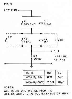
Fig. 3. Modification to Williamson network for greater accuracy, reading
the preamp output on an AC VTVM, for example, and confine measurements
to 20kHz and below, any of these conditions is more than adequate because
in such a case you will not be able to resolve differences much below
0.2dB.
The frequency response of your oscillator can also be a limitation, as its error is equivalent to either a network error or preamp error. Therefore, unless you go to the trouble to validate your own individual network and have a more sophisticated oscillator/detector system, you should not expect much below ± 0.2dB in terms of believable error measurements. In all cases keep the capacitive loading on the output of the network to a minimum (by using short lengths of low capacitance cable and defeating any preamp loading capacitors, if switchable) for greatest hf response accuracy.
Table 1
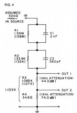
Fig. 4. An alternative inverse network suggested in the Lipshitz JAES articles. Values shown are ideal; closest 1 % values are in parentheses. Output 1 is for a moving magnet cartridge; Output 2: moving coil.
The measured data listed in Table 1 were derived from a sophisticated wide band comparator system, which measures only input-output deviations and uses a DVM for readout of relative dB. It is not a true absolute measuring system (in spite of the high resolution), so the data should be interpreted in relative terms only.
An alternative inverse RIAA network as described ins is shown in Fig. 4. As you can see this design uses the same general network form but has a higher impedance and is thus easier to drive. It is designed to be driven from 300 ohm sources (as noted) with network values optimized for minimum error for such conditions. The circuit of Fig. 4 is the closest one can come to meeting these conditions with standard available capacitor values for C1 and C2 .
With R3 and R4 connected as shown, a second output is available. This is suitable for equalized moving-coil phono preamplifiers, and will exhibit frequency response properties similar to the basic output.
Both these networks can be driven adequately from most preamplifier outputs.
A stereo version is thus suitable for con ducting listening tests on phono preamplifiers, by feeding them with a musical signal from your audio system via the network. This enables one to perform a bypass test on the phono stage of a preamplifier by comparing the input signal to the network with the output o£ the phono stage (after matching gain and polarity). However, if you want to do this, take some special precautions. You must use network components appropriate for listening use. Mica capacitors, while entirely adequate for steady state bench ...
--------------------
WHAT IS AN INVERSE RIAA NETWORK?
THE PHONOGRAPH DISC as a reproduction medium has physical limitations which are off set by altering the bass and treble portions of the spectrum in material to be recorded. In short, the frequencies below 500Hz are cut so they will not take excessive room, and those above 1-kHz are boosted because they are too small to make a good groove.
This cut/boost pattern is standardized into what is known as the RIAA curve, fostered by The Recording Industries Association of America.
The material on your records is supposedly cut to this curve. If you wish to test how well your preamp does the job of restoring the recorded signal to normal and don't have anything but an oscillator which puts out signals in volts, you will have a hard time deciding just how much less bass you should be putting into the preamp at 30Hz to correspond to what the RIAA curve calls for. What you need is a device that does to your oscillator's output what the record maker's RIAA networks do to the signals going onto his recordings.
The inverse RIAA network goes between your oscillator and your phono preamp. If the oscillator puts out the same level at all frequencies (they do not, usually) then if your preamp is correctly equalized, you should get the same output at all frequencies-adding the amplification which the phono preamp sup plies, of course.
The inverse network supplied by Old Colony is passive and has the advantage of not distorting, but it also uses up quite a lot of the energy put out by your oscillator (see Figs. 3, 4), which is a very good thing. The signal your phono preamp wants is very small indeed and your oscillator will do a better job putting out a larger signal, too.
THE EDITOR
--------
... tests, have some dielectric absorption which is undesirable for auditioning tests.
Polystyrene capacitors are preferable for listening, as are metal film resistors.
Input-output connections should be of the highest quality, as should be the cabling used. Finally, you must provide some means of level matching if you intend to use a direct A-B switch. Do not adjust R3 for this purpose, as it will alter frequency response! Of course all of this assumes a top quality line level source, such as a master tape.
Fig. 5 shows a suggested physical construction method for either network.
Leave the shields of the input and output jacks floating within the case. The box is best grounded via a flying lead to its case, which gives maximum flexibility in avoiding noise pickup. Such an enclosure will easily accommodate two networks for stereo use, as you can see from the photos in Figs. 6 and 7.
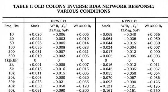
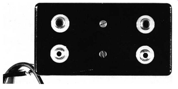
Fig. 6. Jung's stereo prototype network is housed in a cast aluminum
box with gold input jacks, isolated from the chassis by plastic washers.
The box is connected to ground by a separate flying lead attached to
one of the cover mounting screws.
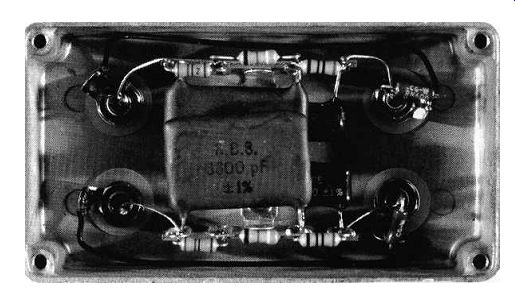
Fig. 7. Interior view of the prototype.
Old Colony is making available a parts kit of suitable accuracy for building a stereo version of the circuit, based on the Williamson design. It will include a cast aluminum box/w. cover, gold input/output jacks, jack insulators, two four-lug terminal strips and all Fig. 3 parts, including
R2 ' /C2 ' for both 600Ohm and 900 Ohm (R3 + RS).
Components are ± 1% or ±2% tolerance; capacitors will be polystyrene. Retrofit kits will also be available for earlier versions of the kit.
As a parting word, don't be too surprised if you measure (and hear) quite significant frequency response deviations on even very expensive phono preamplifiers.
Many of the designs currently on the market are deficient in this regard.
REFERENCES
1. S. P. Lipshitz: Audio Amateur Letters, Vol. 9, No. 3, 1978, pp. 48-49.
2. W. G. Jung: Audio Amateur Letters, Vol. 9, No. 3, 1978, pp. 49-53.
3. W. G. Jung and D. White: 'A PAT-5 Modification" Audio Amateur, Vol. 9, No. 1, 1978, pp. 7-22; see also issue 3/79, p. 24.
4. R. Williamson: Audio Amateur Letters, Vol. 2, No. 3, 1971, p. 22.
5. S. P. Lipshitz: "On RIAA Equalization Networks" JAES Vol 27, No. 6, June 1979, pp. 458-481. Fig. 5. Physical mounting arrangement.
Also see:
Are Those Ears Really Golden? (Or only Iron Pyrites?) -- Extensive explorations of whether listeners detect differences in equipment, by Thomas H. Smith, Michael R. Peterson and Peter O. Jackson
Conversations with Peter Baxandall: Part II Opinion from a distinguished British engineer/audiophile