DEPARTMENTS
- Intro
- EDITORIAL--Musings
- Book Reviews, Reviewed by Ron Miller
- AUDIO AIDS, By Clifford Dunning and Paul T. Kelly
- JUST LOOKING
- LETTERS
++++++++++++++++++
Intro
Our 1985 preamp festival continues in this issue with the Daniel tube design, featuring on-board regulators for each stage, a cascode input and much more. Author Curcio gives an enlightening tutorial, as he walks us through his design and explains the reasons for his choices.
Readers often write to us asking for characterizations of TAA's construction project pre-amps and power amps and comparisons with famous off-the-shelf brands. These are difficult questions because each constructor might build a particular project a bit differently or use different parts. But Bill Cruce, who does neuro-biology research in Kent, Ohio, thought making those comparisons was a job that needed doing. He recruited fellow area audio amateurs Pat Amer and Jim Boak, a lawyer and an engineer, respectively, to evaluate and compare ten preamplifiers . This is an outstanding and herculean effort by these three audiophiles.
Last time, Bill Ruck, KFOG's gift to San Francisco music lovers, tackled the rising tide of power line noise problems. In this issue, he deals with the signals that invade our systems via other media. These intrusions are supersonic, at least, and they find a way into our systems from a number of sources. The answer to any given problem requires complex detective work, and Bill's prose is a good first tutorial on successful sleuthing.
When Heath's engineering staff designed the IG-1275 Lin/Log generator, they did not include a frequency readout. Of course, the controls indicate approximate rates. Bill Schreiber, a professional engineer, has put together a quick, accurate device to remedy the 1275's deficiency. Now you can, too.
We also have Ron Miller's Booktalk and Audio Aids [see below] from Clifford Dunning and Paul T. Kelly.
Next time, John Roberts shares his minimalist preamp design, Gary Galo modifies a turntable, and Dick Marsh discusses the merits of low negative feedback in power amplifiers.
EDITORIAL--Musings
From time to time, a collection of small items ac cumulates in my editorial ideas folder, and this seems a good time to share some of them with you.
Denon, Nippon Columbia's US subsidiary, is working with selected US TV and radio stations using Ambisonic encoder and decoder equipment in test broad casts. No announcements have been made concerning which stations. The hardware is professional level, and the tests are the first step toward possibly introducing consumer equipment. Denon ’s action is part of a much larger response to Ambisonics. The BBC and NHK ( Japan's largest broadcasting enterprise) are making similar broadcasts using Ambisonic-encoded recordings with selected reception sites in Britain and Japan. In the best of all possible worlds, we could hope for undecoded Ambisonic broadcast signals with the option to decode in whatever microphoning format each of us prefers. But my limited listening to Ambisonic recordings makes me certain that even minimal use of Ambisonically encoded audio in TV or FM broadcasts would be a quantum leap in quality and realism.
Speaking of microphones (the Ambisonic system depends wholly on a special four-element mike), two legal incidents involving microphones recently caught my attention. Apparently, the recent series of federal grand jury indictments in New York concerning alleged Mafia crime in a half dozen activities was based on information gathered by a concealed microphone in a Jaguar automobile. This might be characterized as a technological version of the Lone Ranger's famous silver bullet, I suppose.
But that technique works, as any dedicated recordist knows, only if the microphoning is done well. A Jag is probably easier to bug than a back room where a cocaine deal is being made. Such was the problem locale for the drug branch of the Ontario police last year when they attempted to do a 'room probe' in Cobourg, Ontario. According to Ontario Lawyer's Weekly, a justice of the Ontario Supreme Court, W.
Gibson Gray, said he listened to the tape provided by the police with and without headphones and “couldn't make out a single word. ” He threw out the case for lack of evidence. A cautionary tale for all would-be tape buffs, uniformed or not.
I regret to report that the Japanese supplier of the two Monarchy Engineering kits, the A-501 power amp and the A-502 stereo control center (reviewed in TAA 3/83, p. 44, and TAA 4/83, p. 34, respectively) is out of stock indefinitely. The manufacturer apparently is shifting its efforts toward the video market. Monarchy does have a limited quantity of A-1033 tube amps, which Pat Amer will be reviewing next time.
I report all this not only to save readers from unnecessary trouble, but also to comment on the event.
Here is a large Japanese manufacturer shifting its emphasis to video and putting its solid-state equipment at the lowest priority level, while keeping tube equipment generally available. This might reflect the exceptionally high level of popularity tubes enjoy in Japan, but also the slowly growing renaissance of interest in tube technology worldwide.
In other bad news, we regretfully report bankruptcy proceedings for two firms at either end of the country and of the high/low-end spectrum. Mark Levinson and Speakerlab are both in proceedings that protect them against their creditors. This does not always mean demise of a company. It might mean that someone will buy the remains or that new financing will be found. But don't hold your breath.
We were a bit surprised a couple of weeks ago by a telephone call from a reporter for the Manchester (New Hampshire) Union Leader asking whether I had heard about a CBS lawsuit against one of our neighbor publications. It seems that CBS is suing Wayne Green Enterprises for its use of the word “audio ” in the title of its six-month-old Digital Audio magazine. CBS apparently feels that this use of the word dilutes the registered trademark for the title of its Audio magazine. The reporter wanted to know what we might do if CBS lawyers decided to file a similar suit against Audio Amateur. 1 thought a minute and said I supposed we would change our name. Who can take on $2 billion worth of corporation? Not us.
The question set me to thinking. Just in case we get a large, official-looking envelope from New York, does anybody have any good ideas for a new name? Don't dally over this: there are about six other publishers who will be scurrying around looking for nice sounding alternatives, too. And we abhor leftovers.
I also began to wonder whether perhaps the Washington Post editors or publisher might not be interested in the rather curious turn of events that has recently taken place. CBS has just bought a large segment of Ziff-Davis properties, including Stereo Review.
The last time I looked, CBS Laboratories was doing the product reports for High Fidelity. Maybe I am just being picky, but doesn't that mean that product review policy for the three largest consumer audio magazines in the US is made by the same board of directors? Maybe they should make an offer to Wayne Green for Digital Audio to round out their holdings.
No matter what anyone says, however, I don't think Harry Pearson will sell to CBS. It certainly does make life interesting.
-E.T.D.
Book Reviews
Reviewed by Ron Miller
BOOKTALK
by Ron Miller The arrival of Josefa Heifetz's From Bach to Verse (Penguin, $4.95) inspired me to write yet another “Booktalk. ” Ms. Heifetz, even without the enclosed en dorsements from Peter Schickele (a.k.a. P.D.Q. Bach) and Isaac Stern, has wrought a 'marvelous thingling ” (a deliberate reference to Ogden Nash's whimsical verses to Carnival of the Animals). Anyone whose musical taste was almost destroyed by 'Papa Haydn's dead and gone, /but his memory lingers on' or “This is the symphony/that Schubert wrote and never finished' will find here truly humorous verses showing that the technique can work well.
The book takes aim at some 60 widely known classical works from Bach to Weber and from the Violin Partita No. 1, which reads, “Bach wrote for violin all alone/For reasons that are totally un known,” to the Overture to Der Freischuetz, “Carl/Maria von/Weber/ Would often/Snarl/At his noisy/Neighbor. ” This is not audio technology, but if we can't laugh because music is too sacred, we'd better go back to sports.
One theme with which I have dealt in past columns is the issue of learning theory and the practice of our craft. One source of useful material has been the Heath Company. Over the past few years, Heath has published a number of valuable educational courses, as my comments in TAA 1/77 and 1/79 suggest. Recently, the four basic volumes- EE3101, EE3102, EE3103 and EE3104- have been reworked into the two volume Electronics for Hobbyists (EE3140, $64.95). Although this course pays less' attention to minor byways of electrical and electronic theory, it covers the essentials with the same clear text, review quizzes and experiments (with parts supplied) I have come to expect. To participate, you must have plug-in boards with power supplies, a multi meter and an oscilloscope.
Chapters include information on direct current (DC), alternating current (AC), active devices, electronic circuits, digital electronics, digital computers and electronic hobbies. There is, of course, less detail than in the four separate courses, but this is a good introduction to the topic. 7; I have also looked into, but not worked - through, several volumes of Heath's Advanced Electronics Series.
Operational Amplifiers (EE101, $44.95) and Active Filters (EE102, $39.95) are adequate expansions of two books by Howard Berlin-Design of Op Amp Circuits (Howard Sams, #21537, $11.95) and Design of Active Filters (Howard Sams, #21539, $10.95). Each book includes chapter (unit) exams and parts for the experiments, and the information is presented in a large notebook format with plenty of space for notes and problem solving. These give you a good grasp of appropriate theory and some practical applications of it.
My experience with Heath's Printed Circuit Boards (EE3134, $64.95) has also been limited to a thorough examination, and it looks as though it gives the best kind of practical experience for audio amateurs trying to develop their skills.
Although TAA has recently focused more on elaborate circuit designs with high quality parts and complex circuit boards, we all need experience in design engineering and building equipment from scratch. The experience acquired in this course can help you to be better at your craft.
The course includes the kind of descriptive text you would expect, along with the miscellaneous materials needed for the experiments-copper-clad board, photo-resist board, etchant fluid and developer fluid-as well as the parts for two simple projects. Those who want to “roll their own ” and not depend on Heath, Hafler or Old Colony will find this of great value.
There are a number of tutorial books with experiments not yet turned into Heath courses. Each of these is valuable.
Of special interest is Edward J. Pasahow's Learning Digital Electronics Through Experiments (McGraw-Hill Electro Skills Series, $8.95). This book gives readers a solid background in digital theory and appropriate experiments. So far, we have not seen a great deal of digital design in TAA, but the time for that might be approaching. Mr. Pasahow's book describes the basics of CPUs (central processing units) and the rest of computer technology.
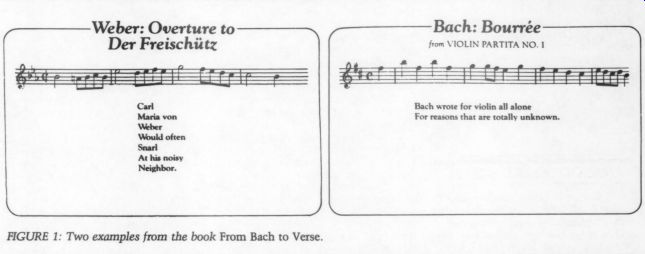
FIGURE 1: Two examples from the book From Bach to Verse.
Weber: Overture to Der Freischiitz Bach: Bourrée from VIOLIN PARTITA NO. 1
AUDIO AIDS
SPACE-SAVING SHELF
OVER THE YEARS, my home sound system has grown, piece by piece. Originally, it was set up on a 7-foot-long shelf unit made from a 2-by-12-inch plank, but I soon realized that a switch to a vertical arrangement would conserve precious floor space. The “rack-style ” cabinets I had seen were too small and expensive, however, so I built my own unit (Fig.
1a) based on a professional 19-inch steel rack used in the sound booth at a local arts festival where I worked.
I bought a 16-foot-long 2-by-12 and two 6-foot-long 1-by-12s, along with four 6-foot lengths of steel shelf-bracket strips and 36 shelf-hanging clips (a dozen to the bag). I cut the 2-by-12 into two 76-inch pieces (for the sides) and two 18-inch pieces (for the top and bot tom). I then cut the two 1-by-12s into eight 17 %-inch pieces for the shelves. A dozen #8 by 3-inch wood screws and wood glue were all I needed to assemble the frame. I left the finish natural. Total cost of the materials was around $40.
I needed such a high unit to hold all my present equipment and to allow room for growth. The heavy lumber helps support heavy equipment with out a lot of back bracing. This allows ac cess in the back for easy patching.
Because of the shallow design, I suggest adding some long feet (Fig. 1b) to stabilize the unit if you are setting it up on a carpeted floor.
I tore down my old shelf unit to make a vertical record cabinet to complement the equipment rack. Both cabinets hold more than the old shelf unit, but use less than half the floor space (about 3 square feet versus more than 7).
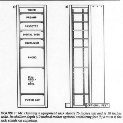
FIGURE 1: Mr. Dunning's equipment rack stands 76 inches tall and is 18 inches wide. Its shallow depth (12 inches) makes optional stabilizing feet (b) a must if the rack stands on carpeting.
Currrorp L. DUNNING
Portsmouth, NH 03801
ANALOG METER SCALES
RANGE OHMMETER by John T. Bailey (TAA 2/84, p. 36) reminded me that adapting a surplus analog meter can save you a lot of money. (See 'Adapting Surplus Meters to Your Circuit,’ TAA 1/82, p. 25.) This involves a very vexing problem, however. Since the surplus meter's scale is almost never usable in the new application, you must construct and calibrate a new meter scale. If you try painting over the old scale, you will quickly learn that it is next to impossible to lay out a new scale-much less calibrate it-directly on the meter. Instead, you must make the new scale separately and then attach it to the meter.
Therein lies the rub. The scale of an analog meter is a chord, or portion of the arc, of a circle whose diameter is unknown. To construct a new meter scale that will fit the meter you are adapting, you must first determine the radius of the circle from which the meter's chord was taken. Once you have done that, you are home free. You can then construct an identical chord and lay out the appropriate scale with a protractor.
Figure 1 shows a simple and easy method for determining the radius of the circle and includes the formulas for determining the parameters of that circle. The center of the circle is the pivot point of the meter's pointer.
You can construct the chord for the new meter scale on a suitable material such as enamel paper. (Vellum card stock also works well. -Ed.)
If the meter you are adapting has a mirrored scale, lay out the chords corresponding to the radii of the top and bottom of the mirror chord. Cut out this portion with a stencil knife, and your new scale will also be mirrored.
It is best to construct two chords to facilitate accurate calibration of the new scale. Temporarily attach one chord to the meter face and use it to lay out the reference marks for the new scale. You can accurately transfer these to the final scale using a protractor and a felt marker. After the new scale is done, carefully attach it to the meter face, using a relatively slow-setting adhesive to allow accurate positioning. Voila! You have a custom meter scale.
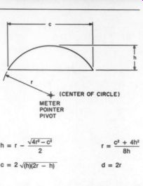
FIGURE 1: This simple procedure allows you to determine the radius of the circle from which the meter's chord was taken. Use the formulas to find the circle's other parameters, where h is the height of the chord, c is the length of the chord, r is the radius of the circle, and d is the diameter of the circle.
I have one caveat regarding surplus meters. Be sure before buying the meter that you can remove the faceplate with out destroying the meter in the process.
Many faceplates snap into place or are held in place by screws or friction, while others are “welded ” to the meter body and cannot be removed without destroying or severely damaging the meter.
PauL T. KELLY; Fort Wayne, IN 46815
SALVAGING SURPLUS PARTS
ONE OF THE HAZARDS of buying surplus parts is the condition in which they are often received. I recently acquired six four-pole, 23-position rotary switches that had been removed from old equipment. These switches cost $18 to $20 new, but I paid only 50¢ each. They were so grundgy and tarnished, however, that I hated to handle them, much less use them in any project. Fortunately, I was able to restore them to like-new condition.
Carefully, I disassembled the decks and put them, one switch complement at a time, into a jar with a tight lid. I then immersed them in Tarn-X (a liquid silver/copper/brass cleaner), swirling the Tarn-X from time to time. In about 30 minutes, they looked like the proverbial new penny. To remove all the cleaner residue, I rinsed the switches thoroughly. After air drying the decks, I gave them a good coating of 10 percent Cramolin Blue and then reassembled them. Voila! They looked like new.
Tarn-X is distributed by Jelmar ( 6600 N. Lincoln Ave., Lincolnwood, IL 60645) and is available at many drug stores. A 12-ounce bottle, which costs about $4, goes a long way.
PauL T. KELLY Fort Wayne, IN 46815
JUST LOOKING
Tandberg has introduced its first series of reel-to-reel decks. The new TD 50 series of 1/2-inch, two-channel recorders will be available in three models, with designs for studio mastering and broadcast use.
The machine has no integrated circuits in the signal path, using only selected polyester capacitors and metal film resistors. In the transport design, all the mechanical components are mounted directly on the rear of a 10mm-thick und of aluminum alloy.
This alloy is molded to extreme tolerance through a proprietary process, maintaining the slab's perfect flatness in its “memory. ” Thus the plate has the ability to return to its original shape if it is ever deformed by stress or tempera need for a chassis, which can inhibit machine repair or adjustment. Because all the mechanics are mounted on one slab, releasing two screws allows you to swing the transport back for immediate access or removal of any part without disturbing other assemblies.
The TD 50 series combines the latest in microprocessor design with state-of the-art analog recording, using an 8-bit microprocessor with 64K bytes of EPROM memory to control the five digit, real-time (elapsed) counter and several other functions. Other features include a built-in tape cutter for editing, easy access to the head block module, solid ruby cylinder tape guides for mini mum wear, a three-motor transport including a direct-drive motor, three tape speeds (15, 7.5 and 3.75 ips), and 12-inch NAB, Cine and DIN reel capabilities. Other options are an RS 232C computer interface port, a VU/control console, and SMPTE and EBU time code systems.
Details on the TD 50 series are available from Tandberg of America, Labriola Court, PO Box 58, Armonk, NY 10504.
Andie + Design Calrec Inc. is the North American distributor of the Minim AD7 and AD10 hi-fi Ambisonic decoders.
The AD10 will accept two-channel, UHJ-encoded signals from records (digital compact disks and analog), tape, broadcast and video, as well as B-format signals suitable for professional playback systems. These will then decode into signals for feeding to a four-speaker system. A layout control compensates for different arrangements. Where speakers are more than 10 feet from the listener, a distance but ton compensates for the different ways in which wavefronts travel at low frequencies. A focus control allows alterations in the perceived sound field, while a position control places more emphasis on sounds from the front or rear stages.
You can use the stereo-enhance control with conventional stereo sources to widen the sound stage from a central mono image to a complete surround sound picture. A stereo-bypass switch allows conventional stereo playback through the front two speakers only.
Special versions of the ADI10 are available to meet monitoring and professional requirements.
The AD? is a simplified version of the ADI10. Smaller in size, it will decode UH] two-channel and B-format signals and includes speaker-layout, stereo enhance and stereo-bypass controls.
Additional information is available from Audio + Design Calrec Inc., PO Box 786, Bremerton, WA 98310.
Phoenix Systems has announced its second generation delay-enhanced ambience/ surround sound decoder. The model P-250 replaces the P-25 for extracting ambience from stereo recordings and surround sound from encoded movies.
For true four-channel reproduction, the P-250 includes a center channel output in addition to the conventional left, right and surround. When the unit is switched to mono mode, a built-in stereo synthesizer improves the sound of even lo-fi mono sources.
Delay time is adjustable from 5msec to 50msec. Other controls include center volume, rear volume and master volume. A push-button switch selects surround mode or simulated stereo. The P-250 is available factory assembled and tested or as a kit from Phoenix Systems, PO Box 628, Manchester, CT 06040.
Two new dual moving MicroCoil phonograph cartridges are now avail able from Signet. The MK440ml, a high end model with a 5Hz to 50kHz frequency range, features the Signet MicroLine stylus tip, which reportedly exhibits excellent tracing and tracking characteristics. A gold-plated beryllium cantilever transmits physical energy from the groove undulations to the MK440ml's dual MicroCoils. Signet chose beryllium because of its rigidity-to-mass ratio, while the gold plating damps out un-wanted resonances.
The Model MK55e provides many ad vantages of sophisticated moving-coil cartridges at a lower price. A frequency response range of 20Hz to 28kHz is achieved through a combination of the 0.3-by-0.7-mil nude elliptical stylus and tapered cantilever, the dual moving MicroCoil and the positioning of the coils in front of the cantilever fulcrum.
Write to Signet, 4701 Hudson Drive, Stow, OH 44224.
LETTERS
CORRECTION:
LANDERS LPDA
I HAVE DISCOVERED three errors in my LPDA article (TAA 5/84, p. 16).
1. In Table 2b (p. 18), the value of h, for the nine-element antenna should be 42.066, not 42.006.
2. In the third paragraph on page 20, the subscript is missing in one of the expressions. The text should read as follows: hy =h,7.
3. In the last paragraph on page 20, I should have said that the cited references found Carrel's calculated gain figures to be too high, not too low.
Lesue C. LANDERS; Sacramento, CA 95864
CORRECTION:
AMPZILLA II
Jim Bonciorno's Ampzilla III power supply diagram (TAA 4/84, p. 13, Fig. 2b) contains an error. C6's positive terminal should connect with the -42V rail, not the +42V rail as shown. The circuit board layout (p. 16, Fig. 4b) shows the correct connection.
Gary Garo Potsdam, NY 13676
CORRECTION:
DIGITAL dB METER
I READ GARY BERGSTROM'S ARTICLE on his digital dB meter (TAA 4/84, p. 24) with great interest. Until now, I have used a vintage HP-type 7561AM logarithmic converter, but I plan to replace its in nards with Mr. Bergstrom's elegant design.
I did, however, discover some inconsistencies between the schematic and stuffing guide. Specifically, the connection of the stabilizer circuit R39/D13 48 (15 to -5V in the schematic) seems wrong in the stuffing guide (-15 to +5V). In the same area is an unmarked resistor between C11 (+) and DI13 (cathode). Although it is no big deal to place the components according to the schematic instead of the stuffing guide, some prospective builders might not be aware of the differences.
Johannes M. DIDDEN; Diepenbeek, Belgium
Mr. Bergstrom replies:
Mr. Didden is entirely correct that R39/D13 are in the wrong holes on the circuit board. See Fig. 1 for the revised portion of the stuffing guide.
FIGURE 1: Corrected portion of the stuffing guide for Gary Bergstrom ’s digital decibel meter.
MORE dB METER CORRECTIONS
GARY BERGSTROM's digital decibel meter is most ingenious and a worthy project for anyone who shares the habit of delving into the guts of those cantankerous boxes that give us both music and nightmares.
Upon inspection of his stuffing guide on page 35, however, a small but mentionable error stood out. A jumper between IC2 pin 2 and the gate of Q1 was left off the drawing. This jumper should cross the two pads just above IC2 and below the dotted line showing back-mounted R53. I fear the omission of this jumper will render the circuit nonfunctional. Since such jumpers are not listed in the text, the problem would be rather difficult to track down.
I have one other suggestion regarding the construction of the device. To bring 60Hz noise to an even lower level, you might consider mounting the power supply regulators in a box outside the meter, along with C10, C11 and C17, while leaving C18, C19 and C25 in the main chassis. This would prevent even low-voltage 60Hz signals from entering the meter proper. Connection to this outboard power supply can be made with an amplifier or Jones-type connec tor. This approach is particularly useful for those of us who have built multi voltage power supplies for interchange able use with several devices.
Changing the subject, I am glad to find that Jim Bongiorno is alive and well (Ampzilla 3, TAA 4/84,p.7). I would like to know whether he is still importing the Three Blind Mice record ings from Japan, and if not, whether he might be able to lead me to a source for these superb disks.
D. GLEN CARDENAS; Boonville, IN 47601
Mr. Bergstrom replies:
Mr. Cardenas is correct in spotting the error on the stuffing guide, and I hope that no one has been inconvenienced by this oversight. Concerning the comment about 60Hz noise, I do not think that removing the low-voltage AC from the box will noticeably reduce the noise, but using an isolated jack for the AC will remove some noise from the metal box. Most units I have seen allow the user to view 10uV signals below about 1kHz, so we are not talking about very much noise.
I would also like to say that I have
had a great deal of experience with this unit, and if anyone has a problem, please feel free to write.
Editor's Note:
Jim Bongiorno reports that Three Blind Mice is now out of business.
BORBELY MOSFET OSCILLATION PROBLEM
SHORTLY AFTER READING Erno Borbely's excellent article on the 60W MOSFET amplifier (TAA 2/82, p. 7), I built one and had no unexpected problems. All aspects of its performance were excellent, and it was sonically one of the better-sounding amplifiers I have heard. Most impressive were the smooth, detailed highs that the amp seemed to reproduce effortlessly.
Recently, however, a problem developed that was not easy to solve. This first manifested itself as a DC offset (2V) on one channel. After taking some measurements, I found that one MPS8099 transistor was “funny. ” I in stalled a new device (Beta-matched to the other device in the differential pair), and the problem went away. After testing my amp on an oscilloscope, however, I discovered a high-frequency oscillation. Touching the MOSFET heatsinks seems to reduce this oscillation; removing the MOSFETs from their sockets and measuring the signal at the gate resistor shows no oscillation. I am at a loss as to how to eliminate this high-frequency oscillation.
Any suggestions? I would like to take this opportunity to tell you how much I enjoy such an informative, well-written magazine as TAA. 1 have POOGed many pieces of equipment with good results. I plan to modify my Dyna ST-416 next per Mr. Rollins' suggestions (TAA 3/83, p. 21).
I would like to see Old Colony make a board (or a kit) available for this mod, as [ am sure many others are interested in updating their 400/416s. I would also like to suggest using Motorola's MJ802 and MJ4502 and the 2N6030 de vices. These devices are “quicker, ” have a higher current capability and are less expensive. I have used them successfully in the ST-150 and ST-416.
I would welcome any information on my MOSFET oscillation problem or re ports from fellow Dyna POOGers. How about building one of Mr. Borbely's new designs on a DH-200 chassis?
MARY Lucia PICCIONE
Hazleton, PA 18201
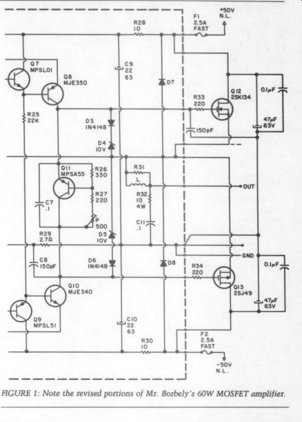
FIGURE 1: Note the revised portions of Mr. Borbely's 60W MOSFET amplifier.
Mr. Borbely replies:
I did not encounter the oscillation problem Ms. Piccione mentions, but it might happen if the wires between the circuit board and the heatsink assembly are long. The gate of the N-channel device likes to see a small capacitor to ground, which is adequately taken care of by C8 (330pF) if the interconnecting wires are very short. If the wires are long, I suggest splitting C8 into two 150pF caps, placing one on the board instead of the 330pF and connecting the other between the circuit board side of resistor R33 and ground.
You might have to create a ground point here and connect it back to the ground pin of the board.
I would also like to make a second suggestion, which concerns the de coupling of the output stage. As I mentioned in a previous letter (TAA 3/82, p. 54), C12 serves as a decoupling device and is normally sufficient when single devices are used. However, a full decoupling, using a 47 to 100uF electrolytic in parallel with a high-quality 0.1uF across each output device, is better when long wires are used. For de tails, see the schematics of the Servo 100 and the DC 100 in TAA 1/84 (p. 13) and 2/84 (p. 17). Figure 1 shows a portion of the 60W schematic with the above modifications. Also note that in the original diagram, there is no connection between R20 and R9 (not shown) to R13 and R21.
I hope these modifications solve any oscillation problems. Please don't hesitate to contact me if you have further questions.
CORRECTION:
BORBELY MOSFET MOD
IN TAA 1/85, we published a letter from E. Borbely concerning modifications to his DC 100 and Servo 100 amplifiers (p. 54). Unfortunately, we printed the wrong schematic in Fig. 1.
Below is the correct portion of the DC 100 and Servo 100 schematics showing Mr. Borbely's changes.
In this issue, we are also publishing a letter from Mary Lucia Piccione concerning Mr. Borbely ’s 60W amplifier, along with Mr. Borbely's reply. The schematic appearing in TAA 1/85 refers to Ms. Piccione's letter and is reprinted this time to eliminate as much confusion as possible.
We apologize for any inconvenience our error might have caused.
-Ed.
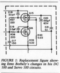
FIGURE 1: Replacement figure showing Erno Borbely's changes in his DC 100 and Servo 100 circuits.
CURCIO CORRECTIONS AND CHANGES
I HAVE TWO CORRECTIONS and three changes to make in my pre-preamp article (TAA 5/84, p. 7). First, the corrections. The formula given for R9 on page 8 is incorrect. It should read as follows:
R9=(V,-15)/(1.8 +3.8)
This will result in the given value of 15k. In addition, the currents indicated for U1 and ZD1 in Fig. 1 of the article are incorrect. The value for U1 should be 1.8mA (not 3.4mA), and the value for ZD1 should be 3.86mA (not 8.5mA), assuming a design center of 15k for R9 (see below).
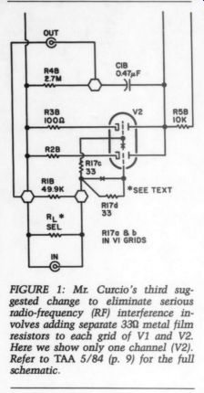
FIGURE 1: Mr. Curcio's third suggested change to eliminate serious radio-frequency (RF) interference involves adding separate 330 metal film resistors to each grid of V1 and V2. Here we show only one channel (V2). Refer to TAA 5/84 (p. 9) for the full schematic.
As for the changes, I think they will improve several of the unit's operating parameters.
1. You can improve low-frequency noise performance by changing the value of C4 from 0.1uF to 1uF (V>250V). Mouser Electronics' ( 11433 Woodside Ave., Santee, CA 92071) part number 19AF001 rated at 1u F, 400V will fit the space provided on the circuit board.
2. Reducing R10 from the given value of 10-ohm to 0.47 ohm will improve the circuit's overall sonic performance.
3. In those circumstances where you cannot eliminate radio-frequency (RF) interference by using capacitors C5a and C5b, you can do so by inserting a 33 ohm carbon film resistor in series with each valve grid (four places- -R17a, b, c, d). This is a “last resort ” effort, since it requires cutting foil traces and tack-soldering (surface-mount technology?) resistors to the underside of the board. If you use this approach, you need not retain C5a and C5b.
I have included a revised schematic (Fig. 1) and circuit board pattern (Fig. 2) to identify these changes.
J.J. Curcio State College, PA 16803
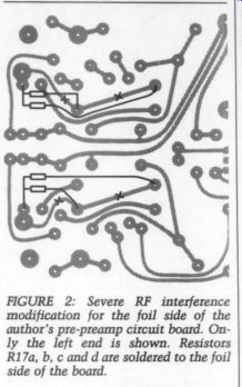
FIGURE 2: Severe RF interference modification for the foil side of the author's pre-preamp circuit board. Only the left end is shown. Resistors R17a, b, c and d are soldered to the foil side of the board.
Editor's Note: We have also discovered errors in the Parts List on page 8. T1 should be a 48V ct, 125mA Signal transformer instead of the value listed.
The Signal part numbers ST-4-48 and S8T-4-10 on the schematic (p. 9) are correct. Also, U3 should be an MC7806T, as listed on the schematic. Finally, the diodes in the Parts List and the schematic should be listed as D1-D?7, not DS.
MORE COMMENTS ON CURCIO PRE-PREAMP
I was VERY PLEASED to read J.J. Curcio's article on his vacuum tube pre-preamp. It seems to be an elegant yet simple design, the kind to which my tastes run. Having done some investigation in this area myself, however, I found several problems with his topology.
First, in this circuit, the grid is biased only 0.3V more negative than the cathode when a 6DJ8 is used. A-40dBm signal with a 1 k-ohm source impedance driving this circuit results in a second harmonic distortion component at the grid, which is 68dB down from the fundamental. This is due to the grid cur rent that is being drawn because of in sufficient bias voltage. (Moving-coil cartridges have much lower impedances and will not produce as high a distortion level. They would still, however, be working into a termination that supplies a net DC current to cartridge on positive signal peaks.) I have also noticed that low-impedance signal sources (read moving-coil cartridges) have a tendency to cause this circuit to oscillate. You can solve this problem by inserting a 100 ohm resistor in series with the grid (between Rsel and the grid). The value of this resistor will not contribute to overall noise when compared to that generated by the tube itself.
Is it possible that either of these problems is related to Mr. Curcio's comment that the sound is 'detailed, bordering on strident'? Second, there are conflicting criteria for determining the value of the plate resistor. Maximum gain and linearity are best served by a large plate resistance, while low output impedance, which is related to the circuit's ability to drive different loads, is best served by a low plate resistance. This circuit has an output impedance of about 2,600-ohm. Perhaps this value is partly responsible for Mr. Curcio's statement that the 'choice of cable at this location...is critical and sonically obvious.’ Without a load termination, this circuit has a 27dB gain with an input level of -40dBm driven from a 10-ohm source and a second harmonic distortion component 66dB below the fundamental.
Is there another simple circuit that will improve upon this one? Certainly it is not the currently in-vogue cascode configuration with its distortion generating low plate impedance load presented to the bottom tube and its very high output impedance. I would like to propose the current-source loaded design in Fig. 1. Its performance is better overall in each of the areas mentioned above, and it accomplishes this with the same number of tubes.
This circuit produces a second harmonic distortion component more than 85dB below the fundamental at the in put when driven from a 1 k-ohm source at -40dBm. This is about a 15dB improvement due to the 0.8V DC bias at each grid. The gain is increased by 3dB to 30dB, and the output second harmonic distortion component is now down by 80dB--more than a 10dB improvement. The output impedance is almost a factor of ten lower at 350 ohm.
Noise performance is 1 or 2dB worse, however, largely because I have used one tube instead of two in parallel for amplification. It is not 3dB worse because the transconductance (g,,) of the tubes is greater due to their higher bias currents. In general, the higher the bias current at which a tube is operated, the lower its noise. (Note that the reported transconductance of 12,500 u-ohm for the 6DJ8 is valid only when that tube is operated at a 15mA bias current. Mr. Curcio's circuit has the tubes biased at about 4mA each, resulting in a lower transconductance.) My circuit works because the top tube provides a very high load impedance to the bottom one. The value of this load is approximately equal to ...
[...]
…where u is the amplification factor. In this case, the load is about 66 k-ohm. The output, taken from the cathode of the top tube, has an impedance given approximately by the equation:
[...]
For this circuit, that value is about 350 ohm . Note how the top tube effectively isolates the sensitive plate circuit o the bottom amplifying tube from the audio connecting cable and its terminating impedance.
Mr. Curcio also presents an interesting idea for a plate supply regulator. He proposes a two-stage approach consisting of an LM317T three terminal regulator cascaded with an op amp-based regulator. I would like to comment on this scheme, some of which also applies to the Sulzer regulator in TAA 2/80 (p. 8) and regulators in general.
National Semiconductor states that the version of the 317 used in Mr. Curcio's design has a typical output impedance of 0.01 ohm below 1kHz, rising to 0.32 at 10 kHz and 2 ohm at 100kHz when 500mA are drawn and the terminal is not bypassed capacitively. When the regulator is run at about the 10mA level, as in this design, these impedances are somewhat larger. The exact levels are academic, however, as the 317 output is connected to the op amp stage through a 10-ohm resistor. The signal component of the tube plate current lows through this resistor, which has some effect on regulator performance.
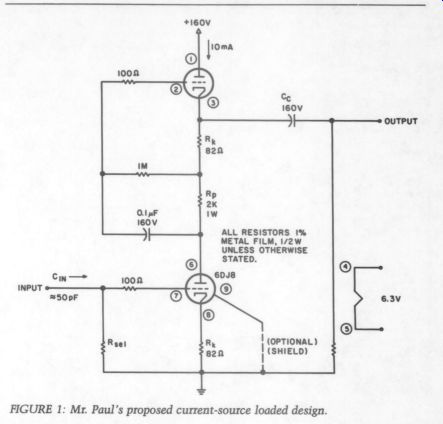
FIGURE 1: Mr. Paul's proposed current-source loaded design.
To analyze this effect, let's call the output signal on tube V1's plates V.
This voltage causes the current V/10 k-ohm o flow through R5A, Q1 and R10 (the 10-ohm resistor mentioned earlier). On the op amp side of R10, the signal (V/10 k-ohm) x (10 k-o), or V/1,000, appears.
This signal is responsible for reducing regulator effectiveness at low and high frequencies through two different mechanisms.
At low frequencies, the low-pass filter formed by R7, R8 and C2 has a cut-off frequency of about 5Hz. Since the low-pass filter input is connected to the point where the signal V/1,000 exists, a 20Hz signal undergoes a total attenuation of about 5,000 before it reaches the op amp's noninverting in put. Because the op amp is configured for unity gain in the audio region, this same V/5,000 signal appears at the regulator output, the emitter of Q1.
Since this would be equivalent to a regulator of zero impedance in series with a 2G (10 k-ohm/5,000) resistor, this regulator has an output impedance of no less than 2 ohm at 20Hz. This is more than 100 times greater than the LM317's impedance at this frequency.
At high frequencies such as 10kHz, the low-pass filter introduces much more attenuation so that an insignificant portion of V reaches the op amp in put. An important op amp parameter- the power supply rejection ratio (PSRR)-has, however, changed a great deal from its value at 5Hz. Valued at about 30,000 at 5Hz, the PSRR at the 351's negative supply terminal falls to 300 at 10kHz. This means that a signal appearing at that point can be considered equivalent to that same signal divided by 300 appearing at the op amp input. The signal appearing at the negative supply terminal is V/1,000, brought there through ZD1. This is equivalent to V/300,000 appearing at the op amp input. According to the method used above, this means the lower bound on the regulator output impedance is 10k/300,000, or about 0.03 . Although this does not seem too bad, were this signal not present, performance would be limited by the impedance of Al at this load current (10mA) and the open-loop gain of the op amp at this frequency, yielding a calculated result of 2 ohm /300, or 0.007 .
How, then, can we overcome these shortcomings? The simplest solution would be to short out R10. The impedance seen at the Q1 collector would then be the output impedance of the LM317T, which is much less than 1010, especially at low frequencies where the problem is most severe. The result is that the portion of V that appears at the Q1 collector is much reduced, thus reducing the portions of V passed on to the op amp terminals and also reducing the regulator output impedance.
The only foreseeable problem that might result from this solution is the loss of current-limiting protection to Q1, particularly at turn-on. In addition to the above modification, therefore, you should place a 10-ohm resistor in series with the Q1 collector. Do not return it to the LM317 output, but rather to the Q2 collector so that the collector-current portion of the signal V does not pass through the LM317. This should virtually eliminate the problems discussed above. The only remaining portion of the signal current drawn from the LM317 passes through the op amp positive supply terminal to drive the base of Q1. If you choose a high-volt age, high-beta transistor such as the 2N5550 for Q1, the signal-current component through the LM317 will be smaller than the full signal current by a factor of the transistor beta, which is at least 60 and might exceed 200. (Remember to decrease the values of R12 and R14 so that the LM317 passes at least 10mA as required by National.) It is helpful to note how the Sulzer regulator deals with unwanted coupling of the signal V to the op amp. The reference voltage is established by a zener powered from the regulator output, not the input, and then low-pass filtered before being fed to the op amp input. Since any signal fed to the input is derived from the regulator output and is much smaller in comparison to what is present there, the regulator output impedance cannot be degraded by leakage of a portion of the signal V to the op amp output.
By adding decoupling capacitors across the opamp power supply terminals, the Sulzer regulator also provides more rejection of the signal V at the op amp power supply terminals than the Curcio design. The Sulzer regulator may well need this if its load has an impedance much below 10k. In this case, the collector current due to the signal V would be proportionally greater, causing a proportionally larger signal to occur at the pass transistor collector (and op amp supply terminal).
The situation merits particular attention when you are using an NE5533, the op amp in the Sulzer design. Unlike National and its LF351 op amp, none of the manufacturers of the NE5533 rate its PSRR. Consequently, it might be particularly poor in this area, thus BEE worsening the problem at high frequencies. Again, the solution is to return the collector current through its own separate resistor to a less-regulated point in the circuit (in this case, positive or negative input). The op amp will be better isolated. Additionally, since R6 (and R1) now are no longer carrying as much current, you can make them larger, further isolating the op amp.
To sum up, when designing op amp regulators, pay attention to minimizing portions of the signal that might appear at the voltage reference or the op amp supply terminals. I was able to do so in the regulator I presented in TAA 2/84 (p. 25) by using three terminal regulators to power the op amp and supply the voltage reference and a completely separate and unregulated supply for the load (signal) current.
CHRISTOPHER PAUL; Hauppauge, NY 11788
Mr. Curcio replies:
I thank Mr. Paul for his interest in and analysis of my regulated valve pre-pre amp, and I apologize for not clearly identifying my design goal--i.e., to provide musical realism.
When undertaking any engineering project, I work backward. First, I ask myself what I want this thing to do, then I examine the elements necessary to achieve that goal. Also, because those elements are imperfect, I consider their limitations and how they can be optimized to achieve the final result. Optimizing the elements is, however, an exercise in myopia, as they are not being used as stand-alone technological achievements but rather as part of a total effort. As such, they must complement each other if the end is to justify the means.
The goal (you will remember) is musical realism, which is a result of carefully configured circuitry that does not alter the definition, dynamics (not to be confused with dynamic range) and precise imaging of the information delivered to its input. I cannot tolerate, even in the presence of the cited at tributes, aberrations such as mid-frequency glare (a common criticism of many 6D]8-based designs). So within the confines of a pre-preamp (not being able to dictate elements such as the cartridge, interconnect and preamp), I presented a recipe with some-but not all-ingredient substitutions.
Let's look at some of the contributing elements.
1. The Amplification Circuitry. In addition to the above criteria, the most important requirement of this stage is low noise. Therefore, I selected the paralleled dual triode configuration. In determining the static operating point, I considered dynamic linearity measurements and listening auditions. The resultant 300mV input margin has not been a problem in actual use.
I realize that I could have optimized other parameters, but they were either irrelevant or in some manner com promised the defined goals. For example, I could have lowered Z_ but knowing that the loading Z_ would be 47 k-ohm or greater, I did not give Z_ high priority.
One significant point Mr. Paul raises is the tendency toward oscillation.
Although he is correct, his solution is not effective in all situations. Instead, you should use two 33 ohm grid resistors in each channel (see my corrections in the letter above). The stridency discussed in the article is a result of the amplifier's overshoot to fast transients.
The grid resistors solve the problem and simultaneously cure any RF (radio frequency) interference. By the way, the circuit Mr. Paul proposes (SRRP) is a design 1 first encountered via Mike Sulzer when we had a large- swing/low impedance requirement in a high power triode amplifier. It performs quite well.
2. The Regulator. Mr. Paul's analysis of R10's effects is correct, but his conclusions are not. The choice of a two-stage regulator scheme is not a result of the ‘more is better' philosophy, but rather a deliberate design mechanism to modulate and control the PSRR of U1. If ultra-low Z_ of U1 were the only criterion, I could have eliminated the 317 (U2), with the bias circuitry (ZD2, Q2, R11, R16) performing the same function around U1. In fact, Mike Sulzer produced the finest and most thorough design of this topology several years ago.
In the two-stage design, the audio signal modulating U1's supply pins is controlled by U2's dynamic Z_. (a function of its external components) and the R10/C3 network. “Shorting out ” R10 unbalances this compensatory action. The value given in the article for R10 (10) is too high (the in tended value was 0.19) and should be changed to 0.47 ohm (see my corrections letter). Current-limiting is provided not by R10 but rather by R16 (as stated). Although the modulation at pin 3 (U1's noninverting input) is now virtually eliminated, you may reduce it to inconsequential levels by adding a 3.3M resistor to the reference line (R7, R8, C2) to form a filter in conjunction with C2 (see Fig. 2 on p. 57). Fortunately, the high Z_ and low input bias cur rent of the 351 allow this solution.
In light of the above and in consideration of the fact that high-voltage transistors are inherently slow, I strongly advise against replacing Q1 with a high-voltage device and, in particular, returning its collector to the Q2 collector. In addition, I have not investigated the effects of the approximately 20V ripple in the current supplied and any loss of protection to the semiconductors during momentary power interruptions. Simply put, this is not a cure.
For those of you who wish to personalize the unit to your own tastes, I have provided limited means to do so. Before making further departures, be sure you have full knowledge of the results.
WANTED:
MODULAR AMP INFO
I AM TRYING TO LEARN something about some of the 'modular' amplifiers advertised from time to time in TAA. Has anyone experimented with these amplifiers? If so, how do they sound in an audio system? In recent issues, I have seen advertisements for the ILP UP60 60W (and other models), the ILP preamp, the Sanyo STK-070 70W, the Rodcar power amp, the Lintech plug-in amplifier modules and the Brown Electronics 50W op-amp design. Specification sheets do not always tell the whole story, of course, and I would be interested to hear how these amplifiers compare with some of the more usual choices in their power range. Surely, one of these might be suitable for a hobby room (living room?) system, but I have not seen any reviews.
---IF YOU SHOULD HAVE A TECHNICAL QUERY . . .. please drop us a note explaining precisely what information you need. We will answer your question ourselves or forward your letter to someone with expertise in that area. Make sure to en close a self-addressed, stamped envelope for our reply, and address your letter to: Audio Amateur, Technical Dept, PO Box 576, Peterborough, NH 03438. Help us out by not calling in your question. We have neither the staff nor the time to respond to each query over the phone. ---
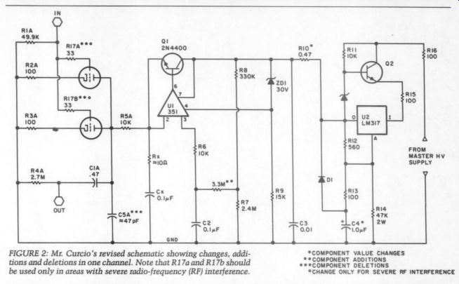
FIGURE 2: Mr. Curcio's revised schematic showing changes, addi tions and deletions in one channel. Note that R17a and R17b should be used only in areas with severe radio-frequency (RF) interference.
CHANGE ONLY FOR SEVERE RF INTERFERENCE
Also, how would these systems compare with the Williamson 40/40 (TAA 4/79) p- 5 ? I presume the 40/40 would win, given the attention it has received in TAA, but by how much? (Have you a yardstick to suggest - Ed.)
I would like to see some comparison reviews of different-class components. Of course, the Phoenix and Hafler preamps are very similar and offer comparable performance, but how do they compare with the Williamson preamp in TAA 2/71 (p. 11). I do not have a problem choosing be tween the Phoenix and the Hafler, but 1 do have a problem choosing between the home-brew (e.g., the Williamson) and a pre-packaged kit. Sonically, how do they compare? Does anyone have some useful experience in this area?
Davo L. DuPuy Lexington, VA 24450
Editor's Note:
See William Cruce's article, “The Great Preamp Shootout, ” beginning on page 19 in this issue.
CINERAMA SOUND
I enjoyed William Sommerwerck's “Ambisonics Comes of Age, Part I ” in TAA 3/84 (p. 7). Although I found the article interesting, I noted with dismay that his discussion of the history of recorded bi/stereo/quad did not include the work of the Cinerama staff.
Most of us who remember the presentations and marveled at the visual portion of the Cinerama films were also impressed with the audio portion.
Granted, nine channels seems like overkill today, and most of us would be broke trying to emulate their mode of recording. Still, there must be a place in Mr. Sommerwerck's overview for the people who gave us sonic thrills with the Cinerama process of sound.
Eucene C. WaLLs Scottsdale, AZ 85257
Mr. Sommerwerck replies:
Mea culpa! I well remember the drawings in Popular Science showing the disposition of the speakers in Cinerama. Unfortunately, my article had to be limited to the highlights of surround-recording history. I suppose I ignored Cinerama because it did not represent any fundamental change over what RCA had done for Disney. For me, the really significant part of Cinerama's sound was its use of magnetic tracks. Note, too, that the article also ignores Dolby MP, as well as Kintek's work with QS and stereo/surround synthesis.
An in-depth history of movie sound would make a fascinating (and long overdue) article for the JAES. I am not qualified to write it, but perhaps Mr. Walls or another TAA reader is. In any case, I appreciate the feedback.
AMBISONIC HARDWARE HUNT
I ENJOYED BILL SOMMERWERCK'S series on Ambisonics (TAA 3/84, 4/84, 5/84).
Please make an effort to publish more specifics on hardware, including de tailed record and playback circuits. I would guess that a large number of TAA readers would be interested in an Old Colony offering that could play existing UHJ format recordings as well as extract some ambience information from stereo recordings.
With respect to Mr. Sommerwerck's suggestion to build SoundField mikes, Digi-Key ( PO Box 126, Thief River Falls, MN 56701) offers Panasonic omni capsules that cost $1 to $2 (Catalog No. 846).
MARK SHULTS Madison, WI 53711
The Editor replies:
We would welcome any input on hardware specifics, along with feedback on Mr. Shults's suggested Old Colony offering. For information on Minim de coders, the only decoders currently available in the US, see Mr. Sommerwerck's report in TAA 1/85 (p. 56).
THANKS FOR SOMMERWERCK SERIES
I HAVE TO say THAT I found “Ambisonics Comes of Age ” to be an excellent series. It is amazing how clear Mr. Sommerwerck is on the subject. I learned a lot. Thank you, Mr. Sommerwerck. And thank you, TAA, for spreading his words.
Dick Marsh Livermore, CA 94550
ALPS ANSWER In TAA 5/84 (p. 58), Cary Murphy re quested information on an Alps stepped attenuator. Star-Tronics ( PO Box 683, McMinnville, OR 97128) has an Alps 100k step attenuator listed in its catalog (No. Y118) for $3 each or four for $10. The minimum order is $4.
Leonard C. Pochor Ontario, CA 91762
In reference to Cary Murphy's letter, please note that besides Old Colony (whose only Alps pot value is of little use to tube-o-philes), the following firms do make Alps and Noble pots available to hobbyists in small quantities: Precision Audio Supply, PO Box 96, Downey, CA 90242; GSI Audio, 576 Nepperhan Ave., Yonkers, NY 10701.
ANDY Fuchs GSI Audio Yonkers, NY 10701
LOUD AND CLEAR
WHERE CAN I FIND a loudness circuit that will work in the Last PAS preamp or in formation on how to design either an active or passive circuit? By active, I mean variable loudness as on Yamaha equipment. I remember an active de sign in a back issue of TAA, but as I remember, it worked at the preamp's high-level output. It seems a waste to build a tube preamp and feed its output through an IC.
DAN WiLCZEK Auburn, NY 13021
-------------------
Also see:
Departments and Regular Columns (Jan 1985)
Noise in hi-fi audio gear (part 1)