I HAVE used the Heath IG-1275 LIN/LOG sweep generator for a couple of years. About the only com plaint I have had is a nagging concern over what frequency it is really generating. Of course, I can use the counter, via a tee connector, but that means tying up the counter most of the time, which is a nuisance. So I decided to devise a simple external digital counter, which would be more or less permanently attached to the generator (Fig. 1).
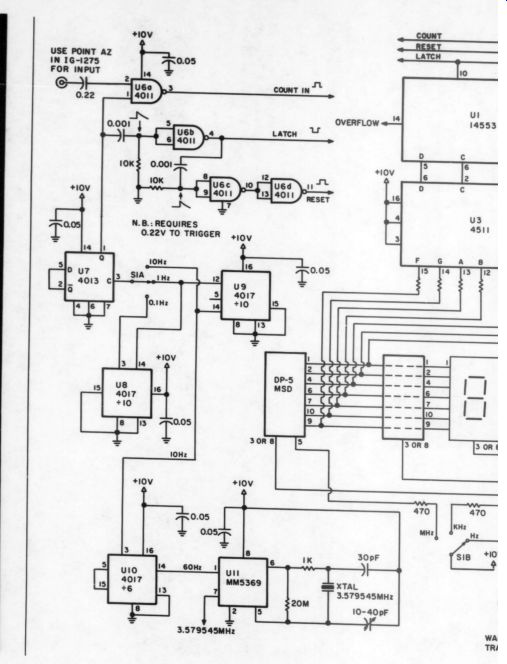
I checked the Archer-Engineers Notebook II by Forest M. Mims ( 1982 Radio Shack, pp. 34-35) and found a collection of circuits that would do the job. I also found a crystal-controlled time base and dividers on page 37. I wanted to be able to display frequency down to 1Hz and up to the approximately 3MHz of my generator. I accomplished this by using the three elements of a 4017 arranged so that I could divide the 60Hz output of the MM 5639 crystal controlled IC down to 10Hz, 1Hz and 0.1Hz (Figs. 2 and 3). You can choose the desired output with a panel mounted rotary switch.
About the only decisions you must make when connecting the counter to the generator are whether or not to hard-wire them together and what pick-off to select in the IG-1275. 1 opted for a plug-in solution and implemented this by adding a BNC connector to the rear panel of the generator (Fig. 4). The pick-off point took a little thought because I did not want to impair the generator's performance. Also, the 4017 triggers on a 0.22V sine wave out to my equipment's 5-MHz limit. I finally chose point AZ for the signal pick-off (Fig. 5). Attaching the counter in no way degraded the signal as viewed on a scope and a harmonic distortion analyzer.
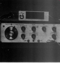
FIGURE 1: The author's plug-in counter is mounted on top of the Heath
IG-1275 sweep generator.
------------------
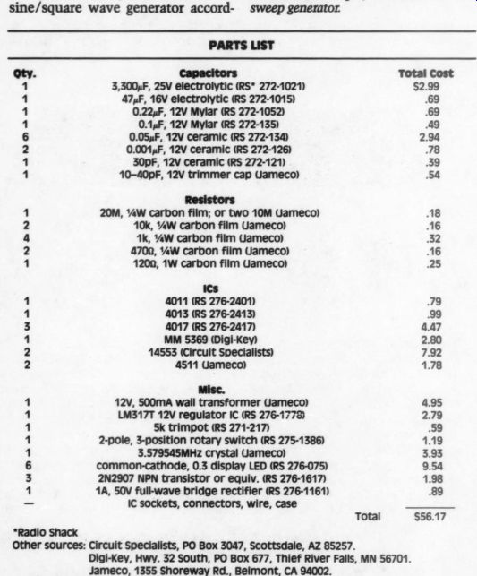
Parts List
Capacitors
3,300 uF, 25V electrolytic (RS 272-1021) :
47 uF, 16V electrolytic (RS 272-1015) 69
0.22uF, 12V Mylar (RS 272-1052) 69
0.14F, 12V Mylar (RS 272-135) 49
0.05uF, 12V ceramic (RS 272-134)
0.001 uF, 12V ceramic (RS 272-126) 78
30pF, 12V ceramic (RS 272-121) 39 10-40pF, 12V trimmer cap (Jameco) 54 294 20M, W carbon film; or two 10M (Jameco) A8 10k, 0.25 W carbon film (Jameco) 16 1k, 0.25W carbon film (Jameco) 32 4700, W carbon film (Jameco) 16 1200, 1W carbon film (Jameco) 25 4011 (RS 276-2401) 79 4013 (RS 276-2413) 99 4017 (RS 276-2417) MM 5369 (Digi-Key) 14553 (Circuit Specialists) 4511 (Jameco)
Misc.
*Radio Shack 12v, S500mA wall transformer Jameco) LM317T 12V regulator IC (RS 276-1778) 5k trimpot (RS 271-217) .59 2-pole, 3-position rotary switch (RS 275-1386) 3.579545MHz crystal (Jameco) common-cathode, 0.3 display LED (RS 276-075) 2N2907 NPN transistor or equiv. (RS 276-1617) 1A, 50v full-wave bridge rectifier (RS 276-1161) 89 IC sockets, connectors, wire, case 4.47 2.80 7.92 1.78 4.95 2.79 1.19 3.93 9.54 1.98 Total $56.17
Other sources:
Circuit Specialists, PO Box 3047, Scottsdale, AZ 85257.
Digi-Key, Hwy. 32 South, PO Box 677, Thief River Falls, MN 56701.
Jameco, 1355 Shoreway Rd., Belmont, CA 94002.
-------------
---------------
-----------
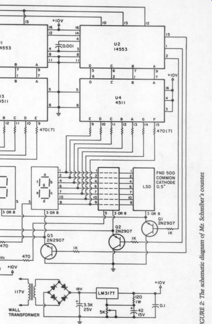
------------ Fig. 2
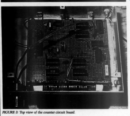
FIGURE 3: Top view of the counter circuit board.
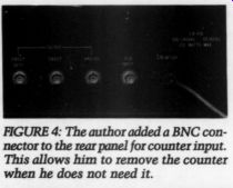
FIGURE 4: The author added a BNC connector to the rear panel for counter
input. This allows him to remove the counter when he does not need it.
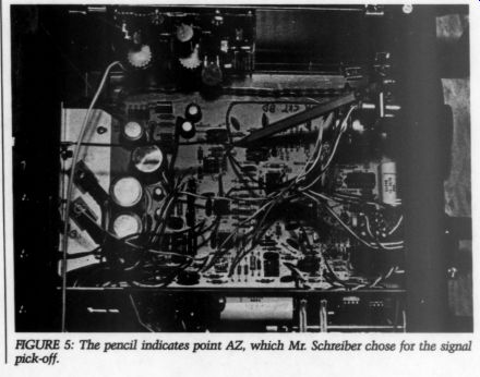
FIGURE 5: The pencil indicates point AZ, which Mr. Schreiber chose for the signal pick-off.
If you rebuilt your Heath IG-18 sine/square wave generator according to Morrey's Super Oscillator (TAA 4/75, p. 3), this counter will indicate the exact frequency instead of the approximation that results from manipulating the decade switches.
Again, it is important to select a pick-off point that is not affected by the attenuators and will not distort the signal. Point F on Morrey's schematic works fine. I added a BNC connector to the rear panel for convenience in connecting the counter.
You can also use the device as a general-purpose counter as long as you meet its input requirements. My test equipment only goes to 5SMHz, so I have not been able to discover the upper frequency limits.
I realize there are simpler, more elegant ways to build counters, but this one is relatively cheap and works fine. The total cost is less than $60 with all new parts, and a well stocked junk box can substantially reduce the price. By the way, the box is made of double-sided circuit-board material soldered together.
-------------------
Also see:
Noise in hi-fi audio gear (part 1)