Depts
- Intro
- EDITORIAL: Listening Virtues
- AUDIO AIDS By Stephen Nitikman, R. Chapula and Willard L. Ramsay
- CLASSIC CIRCUITRY Grommes Hi-Fidelity Model 207A Preamp
- KIT REPORTS The Fujitech A-1033 Integrated Amp
- BOOK REVIEWS
- JUST LOOKING
- CORRECTIONS
- LETTERS
Intro
AA, Contributing editor Erno Borbely takes us to a new plateau in pre-amp design this time with the first half of his two-part construction project. His survey of design choices is illuminating and should give us a basis for fine discussions in forthcoming issues.
Norman Crowhurst's article was sent to me some time ago by a Canadian reader who strongly urged me to reprint it. My reasons for doing so are set out in my editorial below. I thank Mr. Crowhurst for his extensive contributions to audio design and for his exposition of these issues, even though illustrated by examples from tube technology. He poses questions we are only now beginning to answer.
Dick Marsh has significantly contributed to the issues of feed back in amplification by his fine preamp and pre-preamp published in TAA 3/80 and 1/82 as well as his article in 3/85. This time Dick suggests design upgrades for a whole range of commercial power amplifiers in “Pooge 3”.
John Curl and Walt Jung team up to report work on characterizing capacitor effects. As so often happens the idea for such a test apparently occurred to several people at the same time. One researcher at Analog Devices has used the technique to compare resistor performance. I hope many of you will try the test and share your findings.
Pat Amer's report on a tube amp/ preamp (see below) and we have three fine audio aids (see below).
Next time: you'll see Erno Borbely's Preamp, Part 2, Roy Trumbull's Stereo TV report, Gary Galo's turntable speed control and a whole range of new riches due out to start off the 1986 series.
Editorial
LISTENING'S VIRTUES is time we follow Martin Colloms' 3/85 article with Norman Crowhurst's “Some Defects in Feedback Amplifiers.”
My purpose is to document yet again the fact that our performance tests for amplifying devices are grossly inadequate. Crowhurst's text is 28 years old.
His questions remain, however, largely unanswered. Some 1500 listening tests, both single and double blind, are the basis for Martin Colloms' article in 3/85, even though we did not include a bibliography. Some of you assumed-- opinions were based on subjective listening one.
His article and the Cruce article in 2/85 have produced lots of correspondence, some of which appears this time and raises yet again the controversy which began in these pages some five years ago.
The polarization between those dubbed Golden Ears or Meter Readers is unfortunate.
Both groups are, too often, asking the wrong question, namely ‘who is right?' And too many are doing what we are tempted to do when we are angry: calling each other names.
That will never improve any audio gear.
Isolating and defining the significant factors in signal processing quality is the task before us. My prejudice leads me to predict amateurs will do the job. The audio manufacturers have done very little original research but are willing to capitalize on any buzz words that someone coins in an AES paper, or even in the “underground ” publications some manufacturers profess to despise. Feedback (negative and positive) damping factor, TIM and film capacitors are all ideas which public relations min representing manufacturers seem quite willing to seize, researched or not, and make use of as selling points. And company managements will follow a suggestion that better quality coupling capacitors sound better without doing any homework: single or double blind. And they do so with an attitude that if this brand of “chicken soup ” will persuade the customer to buy the product, put it in.
A very large proportion of graduate engineers I have talked to over the years subscribe to the thesis that the relative quality of electronic parts does not make any very significant difference in sound quality. Yet I have never seen any objective proof for that assumption. From the practical, economic viewpoint of the manufacturer, the choice is understandable. But the dogmatism with which some engineers flatly assert the 'truth' of the unproven assumption is highly suspect. Some agnosticism among engineers on a few subjects would not only be more becoming to their professionalism, but would improve the climate for productive discussion.
Since we cannot expect the manufacturers to do their homework (many are even letting the Japanese do it for them) if it is to be done at all, it will be done by academics or amateurs.
As an example, outstanding work has been done already in the loudspeaker field by A.N. Thiele, Richard Small and Siegfried Linkwitz: two university teachers and a designer of microwave systems for Hewlett Packard.
In this issue two professionals give us a de vice for a closer look at capacitor behavior-but their work is a personal investment in improving sound quality--an amateur investment--since it was done mostly for love and a small amount of money.
We need more work of this sort if the theses arising out of our collective listening experiences are to be tested scientifically. What are the significant, un-quantified variables? We can waste a lot of time if one crowd of people is shouting “we hear differences, ” and the other is responding “no you don't. ” I do not doubt that some currently suggested remedies for bad sound will ultimately be classified as snake oil. But some factors are causing the differences and we need to know what those are. Our time will be better spent seriously exploring one of them to a conclusion, rather than running tests to prove some guru cannot hear, or dreaming up ever more esoteric untested possibilities.
-E.T.D.
Audio Aids
POWER AMP SWITCH ONE OFTEN-NEGLECTED point in constructing a preamplifier is consideration of the preamp’s power switch capabilities. Be cause a preamp often switches on its companion power amp, the switch must be rated to handle the power amp load safely.
This brings two problems to mind.
First, panel cosmetics might not allow you to use a bulky, high-current switch.
A very small power switch might be preferable for a low-profile preamp. Second, in the interest of compatibility, a properly designed preamp should be able to operate any consumer power amp on the market today. This is not an easy ...
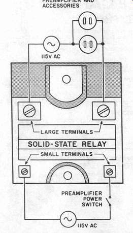
FIGURE 1: Using a solid-state relay allows your preamp switch to handle
the power amp load. OUTLETS TO POWER AMPLIFIER, PREAMPLIFIER AND ACCESSORIES
... task because amplifiers with output capabilities of 200W/channel or more are readily available. One possible solution is to use a standard high-current relay connected to the preamp power switch, whose contacts control the load.
I think my solution is much more elegant.
Using a solid-state relay in the preamp (Fig. 1) provides several attractive benefits. Several manufacturers, including Potter and Brumfield, International Rectifier and Teccor offer such relays.
Besides incorporating triac switching, these block units contain radio-frequency interference (RFI) suppression, isolation, zero voltage switching, and a load of less than 6mA to the input circuit. They control loads of up to 40A.
I use International's Crydom TA1210 for 10A loads and TA1225 for 25A loads in the same way that I would use a standard SPST AC relay.
With negligible load at the input, virtually any switch rated at 117V and a suitable solid-state relay are capable of handling any power amp. The only real drawback to these electronic relays is their relatively high price. Listings in my catalog show the TA1210 selling for $24.36 Canadian. Perhaps the price is lower in the US. (International Rectifier's main office is located at 233G Kansas St., El Segundo, CA 90245. Contact them for price information.) Nevertheless, if your preamp is something special, a solid-state relay is probably well worth the investment. I use one in my modified Marsh preamp, and it switches on a Pass class-A amplifier without any difficulty.
Alternatively, you may construct an inexpensive solid-state relay using RCA's low-cost zero-voltage switch ICs in the circuit shown in Fig. 2. Be sure to heatsink the triac adequately in this circuit.
STEPHEN NITIKMAN; Don Mills, Ontario M3B 2P9
HIGH-END PHASE ALIGNMENT
This IDEA occurred to me while I was designing a delay filter for a telephone test set. As you know, the second-order Butterworth filter is perhaps the most popular crossover configuration of all time. Countless commercial and home brew loudspeakers use this workhorse topology. This design does, however, have some significant defects.
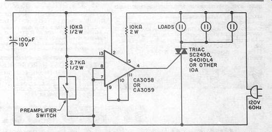
FIGURE 2: Constructing an inexpensive solid-state relay with this circuit
is an alternative to investing in a ready-made device.
If the tweeter is hooked up in phase with the woofer, the output at the crossover frequency is cancelled. […] has been to reverse the polarity of suck-out, but it causes a 3dB bump in the response at the crossover frequency.
[…] this by adjusting component values, thereby yielding a second-order Linkwitz-Riley filter, the tweeter output is still in reverse polarity. This is the problem I am addressing here.
The circuit in Fig 1. is a first-order, all pass filter. Its gain is unity for all frequencies. Its output, however, is in […] with then […] and rotates 180 degrees as the input frequency is increased until it is out of phase with the input at high frequencies. (The input impedance of this circuit changes over frequency, so be sure to drive it from a low-impedance source.) Now, let's take one of these circuits, set the f. to the same frequency as that of the loudspeaker and hook it up before the power amp feeding that loudspeaker.
The net result is this: at low frequencies, the loudspeaker is in phase with the in put. At the crossover frequency, the speaker is 180 degrees out of phase with Choose a value for C.
Then R = 221.0
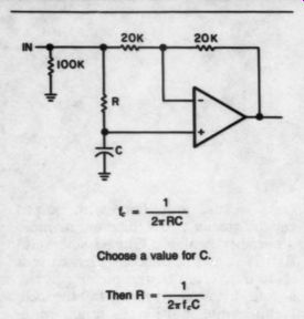
FIGURE 1: This first-order, all-pass filter keeps the output in phase
with the in put over a greater portion of the audio spectrum.
the input. At higher frequencies, the output is once again in phase with the input. Therefore, the output is in phase with the input over a greater portion of the audio spectrum than it is without the all-pass filter in the circuit.
Designing a filter to fit your speakers is an easy task. Most manufacturers re port crossover frequencies in their published data. Use the formula in Fig. 1 to set the all-pass filter's 'crossover' frequency to the same value. If you have a three or four-way system, just cascade filters, one for each crossover frequency.
Evanston, IL 60202
SHACK SINKS RADIO SHACK'S COPPER micro-clips make ideal heatsinks for the installation or removal of heat-sensitive components on circuit boards and are a must for polystyrene caps. The jaws are small enough to allow you to attach three clips to a TO-92 transistor. This allows very little heat to get by to the body of the device, thereby ensuring no dam age. A package of ten clips costs less than $2.
Willard L. RAMSAY; Newcastle, NB E1V 2P1, Canada
Classic Ckts
-----46/47
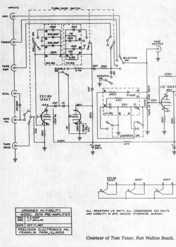
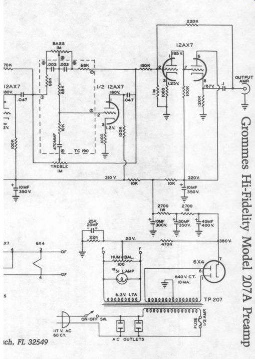
ALL RESISTORS 1/2 WATT, ALL CONDENSERS 4C2 VOLTS AND CAPACITY IN MFD UNLESS OTHERWISE MARKED.
Kits Report
THE FUJITECH A-1033 INTEGRATED TUBE AMP Reviewed by Patrick J. Amer I HAVE Always BEEN a confirmed solid-state man, but the Fujitech A-1033 integrated tube amp kit is making a convert of me.
I have built and listened to a number of very good tube preamps and amps, but I have always come back to solid state for clarity, cleanness and the absence of that warm, beguiling, but not quite faithful “tube ” sound. The A-1033, imported by Monarchy Engineering ( Box 5517, S. San Francisco, CA 94080), exhibits the detail, the last dying reverberation and the musicality of good solid-state equipment. This is a winner, at a bargain price of $449.
The designers must have felt they had a winner, as the A-1033's front panel bears the following legend: 'This model is designed under full command of perfect knowledge about vacuum state technology.’ Eat your hearts out, Conrad and both Johnsons! Maybe some thing was lost in the translation- something was sure lost in some of the assembly instructions.
Description:
The A-1033 is actually a full-function preamplifier and a 15W (or 30W) amplifier in one chassis, with a common power supply. The signal portions of the preamplifier and amplifier are not connected; you use an external jumper to connect preamp out and amp in to operate as a unit.
The preamp section has a volume control, a balance control with a center de tent, a mono/stereo switch, and de tented bass and treble controls, with turnover frequencies of 300Hz and 3kHz. The phono stage amplification is not sufficient to accept a low-output, moving-coil cartridge (in my case, a Dynavector 23R) without separate pre preamplification or unacceptable hum.
The A-1033 has no defeat switch for the tone controls, but it does have a headphone jack. It has input jacks for phono, auxiliary, tuner and two tape decks, with tape-monitoring capability.
An excellent seesaw switch operates smoothly to select phono, tuner or auxiliary input, and signal lights on the control panel indicate the input selected.
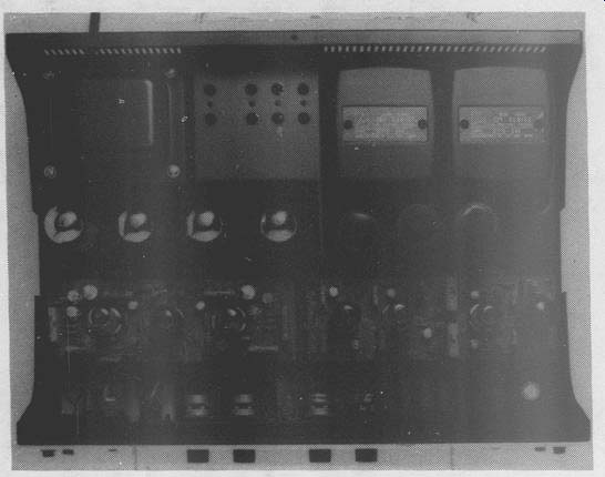
PHOTO 1: An inside view of the A-1033 taken from the top.
Two AC outlets are included, one switched and one unswitched. The tube complement for the preamp section is four 12AX7s, and one half of each tube is used in each channel.
The amplifier section has no controls.
Its tube complement is one 6AQ8 at the input, two 12AU7s as drivers and four 6CA7/EL34s at the output stage, which will help warm your listening room on a cold winter night. You may hard-wire the output tubes for pentode or triode operation. The former yields a 30W out put, while the latter produces a 15W output. I built mine in triode mode, advertised as the mode for “Class-A like performance. ” I later converted to pentode mode for listening tests, then went back to triode. This conversion involves changing two resistors and four capacitors on the circuit board; changing one connection between each output tube socket and the output transformers; and readjusting the bias and DC balance. It took me about an hour and a half to do.
The amplifier contains two large output transformers and an even larger power transformer, and the assembled unit weighs about 42 pounds.
In the preamplifier, the phono section is a two-stage voltage amplifier with degenerative feedback in the first stage and the RIAA equalization in an overall feedback loop. The high-level stage uses two straight voltage amplifier tube stages as input and output buffers to the tone controls. The amplifier has a simple voltage-gain input stage feeding through a resistive inverter to the driver stage, which consists of two sections of a 12AU7. The amplifier section has one overall feedback loop, but no feedback within stages.
Jim Boak describes the A-1033 as a classic tube design from the late 1950s and early 1960s. The power supply is soft and unregulated, there is very limited use of feedback, and the overall design is simple. In this, he observes, the A-1033 is unlike any tube audio circuit design made in the US in the past 10 or 15 years. It is effective not because of the tightly controlled and complex error correction design, but because of elegant execution, classic design principles and the use of high-quality components. Mr. Boak was amazed that this approach could produce such superb sound reproduction, and he says that its success has made him reexamine his own design principle.
Layout of the A-1033 is shown in Fig. 1. Across the top of the picture, which is the back of the unit, you can see the power transformer, the cover over the power supply choke and the AC convenience outlets, and the two output trans formers. In the next row are the four 6CA7 output tubes and to their right, the three power supply can capacitors.
Below and to the front of the output tubes is the amplifier circuit board, with three tubes mounted on it, and to its right is the preamplifier circuit board, with its four 12AX7s. In front of these circuit boards is a long, narrow board on which the control pots and switches are mounted. A small circuit board containing the smaller power supply circuit components is mounted from the bottom under the choke. The rest of the chassis is accessible from the underside, and all the wiring is done from that side.
Preparing for Assembly
Assembly took me about 30 hours, stretched over a period of a couple of months. This is less than half the time I needed to assemble the Fujitech A-502 solid-state preamplifier (TAA 4/83, p.36). The assembly manual, with copious diagrams and illustrations, is writ ten entirely in Japanese. The kit comes with a 32-page translation, supposedly in English, of some (but not all) of the manual. The principal difficulty you will encounter is with the inadequacies and failures of the translation.
My description of the assembly process is intended as a supplement to the assembly manual and the English translation. With this guide, you should have no qualms about tackling the kit. I will try to point out every case in which the translation needs correction or additional explanation.
At the outset, you must disassemble the chassis, which is partially assembled for transportation. Here the translation fails to list all the screws you must remove. A comparison with the Japanese text makes this evident, even if you (like me) cannot read a word of Japanese. This is typical of the entire translation. I suggest that you compare every sentence in the English translation with its Japanese counterpart. In the event of discrepancy, follow the Japanese instructions. The English translation almost always gives you enough help to do this. (In one case, the English instructions are missing, and if you do not catch the deletion, the unit will have no AC power cord. While the accompanying instructions clarifies what you must do.) You should also use the parts lists in the Japanese manual. They not only pro vide an indispensable guide when you open and inventory each of the eight bags of components, but they also give, for nearly every part, a universal identi […] name. This is often helpful when you must verify or correct an instruction in the English translation.
You will also find it helpful to learn the Japanese characters for the names of colors. You can learn the characters as you sort resistors, using the international color code and […] ing the identified colors with the Japanese characters (un-translated) in the parts list. Then practice on the parts list of the many colors of hookup wire. This will enable you to verify the colors of the wires during the wiring procedure. It might seem like a small point, but it is disconcerting to find the English instructions asking you to connect a yellow wire from the head phone jack when the only wires previously connected to the jack are gray, green and black.
Assembly
The kit contains four circuit boards for the preamp, amp, front panel and smaller power supply components. (The instructions say that the board for the front panel controls is “to accommodate the parts/components for the functions relating to functions. ”) I spent the first eight or ten hours stuffing the circuit boards. Layout is clean, and the instructions are clear, but you might need a magnifying glass to check your soldering connections.
After you have stuffed the boards, pre wire the preamp and amp circuit boards.
This is helpful because the boards are somewhat difficult to get at when mounted in the chassis. The page of instructions on wire […] tion is untranslated, so you will have to do the best you can with the pictures. The kit includes six dud colors of heat shrink tubing, and the instructions counsel that 'to use the heat-shrinkable tube, the wax flame and lighter are effective instead of the soldering iron.
However, prevent from possible burning of the tube itself.’ The wiring is straightforward, but the instructions contain two errors that are difficult to correct when they later be come apparent. Wire 21 on CB-A1033B should be 41cm long, not 14, and wire 4 on the headphone jack should be yellow, not black. In a departure from the wiring techniques used in Dynaco kits or in the Fujitech solid-state kits, wires are inserted from the foil side of the board, not the component side, and are soldered on the foil side. This is clumsy, and it takes a little practice to leave enough bare wire on the insertion side so that you do not burn the insulation and can make a good connection. I got the knack of it after a few tries and did not end up with any bad connections.
Once the pre-wiring is complete, you can turn to chassis subassembly. On a subpanel, mount the power switch, headphone jack and circuit board on which the remaining front panel controls (remember-the functions relating to functions) have been mounted. Then mount the subpanel on the front panel.
It took a little bending and wiggling to get everything to line up-the problem was the headphone jack-but eventual ly it all fit quite nicely. Assembling the rear panel was no problem, but wiring the phono jacks was very close and tight work. In a clear translation error, the instructions throughout this section call for shielding capacitor leads and jumpers with heat-shrink tubing instead of insulation tubing, which is specified in the Japanese instructions.
The next step is chassis assembly.
There are three multistage capacitors.
Only the 47uF x3 550V cap is to be wrapped in shield paper, not all three, as the instructions seem to imply. The remainder of the instructions are clear enough, if you rely primarily on the diagrams in the manual. Guide the wires attached to the preamp and amp circuit boards through the subchassis, as you will attach them from the underside.
The assembled chassis weighs more than 40 pounds, so be careful.
Wiring the chassis is next. The dia grams in the manual are very good, but some of the wiring is in very tight spots, and you must watch the soldering iron to avoid burning nearby wire insulation.
Instruction 5 on page 34 of the manual, wiring procedure 2, should call for the green wire from 5a, 6a of CB-A1033A, and instruction 16 on page 36 of the manual calls for the brown wire from CB-A1033A.
Wiring the power transformer is tricky. The instructions are especially obscure here, and you might have to work it out with the aid of the schematic, which gives the color coding of the primary but not the secondaries, and a study of the power supply circuit board layout. My task was complicated by the fact that the shorter brown leads (which provide the power for the front panel signal lights) were mounted at the opposite end of the transformer from that indicated in the manual and diagrams.
Note that on page 39 of the manual, but not in the translation, you are instructed to connect the AC power cord. When you wire the output tube sockets for the pentode or triode configuration, be sure you are consistent with the choice you made when stuffing the amp circuit board.
-------------

Output Power Triode: 15W + Distortion Total Harmonic 15W (40, 80), 11W + 11W (160)
0.15% (8Q, 1kHz, 10W)
0.4% (80, 1kHz, rated output)
Rated IM 1.2% (82, 50Hz to 10kHz, rated output) 1.2% (80, rated output) 60Hz:7kHz = 4:1 Frequency Response Input Sensitivity phono-2.2mV others-190mV main in -0.8V phono-50 k-ohm others-90 k-ohm Input Impedance main in-200 k-ohm phono-better than 72dB others-better than 92dB Signal-to-Noise Ratio (IHF A weighted, input short circuited) Damping Factor 30Hz to 30kHz (within - 1dB, 80, 1W) UL: 9 (80, 1kHz) Triode: 10 (80, 1kHz) Tone Control Additional Features NF type (turnover points-low, 300Hz; high, 3kHz) tape selector (source, tape 1, tape 2) mode switch (stereo, mono)
Dimensions headphone jack (82, 0.3W max) 450(W) by 158(H) by 325(D) mm (172%, by 6742 by 121%, inches)
--------------------------
The Fujitech manual and translation contain an elaborate and careful check out procedure, which provides voltages for about 45 checkpoints. Voltages with in +20 percent at these points seem to be sufficient. You set DC bias and balance by adjusting variable resistors in each channel with a standard voltmeter.
You can adjust these quite precisely. If you have access to a signal generator and a distortion meter, you can adjust the AC balance as well.
After checking that the preamp and amp function properly, complete the assembly by attaching the front panel, control knobs, bottom plate and feet, and cover. The input and output tubes of the preamp section and the input tube of the amp have metal shields, which are grounded to the circuit boards. The in put tube of the preamp is also fitted with a little rubber jacket, which slips over the metal shield, to prevent possible noise caused by ambient light. This is just one indication of the care taken in designing this unit. The front panel signal lights are shielded from the rear to keep the light from shining into the cabinet and out the top. The components and parts, both electronic and mechanical, are of the highest quality, and the finished product is satisfyingly solid.
I have gone into substantial detail in describing the assembly and my problems with the translation to help-not discourage-those of you who wish to undertake this project. The kit is well designed, and the problems with the translation guide are an annoyance (and 2 source of innocent merriment), not a serious impediment. My own A-1033 functioned perfectly the first time and has continued to function without problems. I have not noticed a turn-on or turn-off transient, and hum is minimal.
Listening Tests
The A-1033 is at once one amplifier and two quite different-sounding amplifiers.
Let me first report on the preamplifier section. I performed all listening tests on my present system, which consists of a Dynavector 23R cartridge, mounted on an SME3009I1 arm on a Kenwood KD500 turntable, and my IMF TLS5011 speakers, biamplified through a Jung type crossover. The woofers are driven by a POOGed Hafler 500, and the amplifier section of the A-1033 was tested, in the triode and pentode modes, as a midrange and tweeter driver only.
For the preamplifier section, the reference preamps were the Fujitech A-502 and the Conrad-Johnson PV-3, but because of the recent extended comparisons chronicled in “The Great Pre amp Shootout ” (TAA 2/85, p. 19), the A-1033 has been measured against all the preamps discussed in that article.
Bill Cruce listened to the A-1033, and I believe I am correctly reporting his views as well.
The A-1033 preamp has a clean, smooth sound. It does not seem to have the characteristic ripe warmth I have come to associate with tube equipment (and regard as a distortion, although a pleasant one), but the slight hardness and dryness characteristic of even very good solid-state equipment is absent.
The A-1033 is smoother and warmer than the Fujitech A-502, a preamp I like very much. This smoothness is accompanied by great detail. Separation of instruments is superb, and reproduction of the small details that make for realism and musicality-instrumental placement, hall reverberation, depth of sonic image-is excellent. In this respect, the A-1033 is at least the equal of the A-502 preamplifier.
The A-1033 audibly outclasses the parison, too bright and shrill and does not provide quite the separation and detail of the A-1033. If you refer back to the extended comparisons in ‘The Great Preamp Shootout,' you will see that the A-1033 preamp belongs at the highest level. Overall, it is superior to the Fujitech A-502, the Conrad-Johnson PV-3 and all the preamps rated equal to or below those two. It deserves close comparison with the Conrad-Johnson PV-5 (a comparison that, I am sorry to report, we did not make) and other near state-of-the-art high-end (and high priced) gear. For less than one-third the price of a Conrad-Johnson PV-5, you get a comparable preamp-and an amplifier for free! what the ad calls the “ultra-linear ” pentode mode has twice the power (30W versus 15W) of the amp in the triode […] A-1033 when sold in assembled form, and that manual states the output power it30W. I gather, then, chat only […] the amplifier in triode mode. Other indications in the assembly manual imply that Fujitech assumes that most builders will choose the pentode mode for its greater output power.
The pentode mode amplifier is […]. It dose net have good separation, […] another, when compared to the solid state Fujitech A-501, a very good amplifier. With the pentode A-1033, vocal and instrumental entrances and exits do not […] dissociated from their accompanying sibilant or aspirate entrance sounds.
This indicates some nonlinearity. In addition, the chords just do not seem to tune properly. I soon tired of listening to the A-1033 in this mode.
The A-1033 in the triode mode is another story altogether. Here is clean, detailed, tightly damped sound reproduction without dryness. In 'The Rose,’ from Amanda McBroom in words […] warm a : not nasal, and the image is immediate and present. On the Hammerklavier Sonata (Pollini, DG2530 869), the piano is highly articulated, with no smear or dryness. There is superb balance, with the vocal or instrumental entrance sounds fitting with realistic effect into the continuing sound. Finally, the chords tune, as the reproduction of the o overtones and harmonic fundamentals is correct and undistorted. I think the Fujitech A-501 is a great amplifier in the Class A mode, but I have come to prefer the A-1033 in the triode mode.
The drawback of the triode mode is the 15W power output. This will simply not be enough to drive most full-range speakers; even the fine-quality mini speakers now available usually require much more power. I recommend biamping. The A-1033 functions superbly in my system as a midrange and tweeter amplifier. With a crossover at 375Hz, 1 have not been bothered by clipping, and with a Hafler DH-500, I am not going to run out of power in the bass.
Once again, the A-1033 is good enough to cause designers to rethink their assumptions. As Jim Boak ob served, no designer of tube gear in the past 15 or 20 years has used a triode out put stage because of the limitations of power. Their efforts have been devoted to controlling the inherent nonlinearities of the pentode mode. The designers of the A-1033 have taken a different tack and have combined the inherent linearity of the triode with very fine output transformers in a simple amplifier circuit. The result is audible. The amplifier does not have to work to overcome its problems; it simply reproduces the sound with linearity, correctly and directly. Every serious student of tube design should study it.
For non-theorists who want to listen to good music reproduced well and who enjoy the task of assembly, I cannot recommend this kit highly enough. It brings out the music in my records and makes listening a joy. Maybe, after all, it was 'designed under full command of perfect knowledge about vacuum state technology.’
Manufacturer's comments:
This is an accurate and interesting review, and we wish to thank Mr. Amer for putting the kit together and writing the review.
The translation from the Japanese manual was copied verbatim from the manuscript written by the export staff at Luxman Corp., the factory that sup plied this kit. Understandably, they were not technically oriented enough to take up the task, and we apologize for the small mistakes and discrepancies in the translation. Hence, we do not recommend this kit to first-time kit builders. To avoid further confusion, we will supply the translation in exactly the same manner as furnished to the reviewer.
The page of instructions on wire preparation was translated, but it probably was omitted in the copy sent to the reviewer.
There is an owner's manual, written in clear English, that comes with the factory-wired version of this kit, designated as the LX33. This manual ex plains all the controls and AC-balance adjustments. We will now include it with the kit.
We have a limited quantity of this kit in stock and have no plans to import fur ther quantities. I suggest that potential customers who want to buy this kit call us at (415) 873-3055 (ask for Miss Tomiko) to check availability and the freight charge before they send in their orders.
C.C. Poon Monarchy Engineering
ABOUT THE AUTHOR: Pat Amer is a lawyer in Cleveland, Ohio, where he has practiced law since graduating from the NYU School of Law in 1963. He has been a member of the Cleveland Orchestra Chorus for 12 years and is a frequent contributor to TAA.
Book Reviews
IC VOLTAGE REGULATOR SOURCEBOOK
Reviewed by James Boak In THE course of my work as an engineer, I am called upon to design, specify and repair power supplies on a regular basis.
These may be as simple as a step-down transformer or as complex as an NBS traceable calibration standard, but they have one thing in common: they are at the heart of all modern electronic design and implementation. No other portion of an electronic subsystem affects performance as directly as the power supply. Therefore, a understanding of the present state of design is essential for anyone involved in modern electronic hardware.
Despite the importance of the power supply to overall design performance, it is not treated in great depth in most Rarely does a single reference contain all the basic regulator design concepts and also all the most modern realizations of those concepts. This is what Vaughn Martin has done in his book, IC Voltage Sourcebook With Experiments (Tab Books, 1983, No. 1557; softbound, 256 pp-, $10.95).
The structure of the book is ideal for a college-level course in power supply design. Each chapter provides theory, design examples based on the theory, formulas for doing additional design work, and an experiment or two calculated to give the reader a thorough grasp of the material. The author does not talk down to the reader, but he also does not assume a great deal of electronics or mathematical background.
Mr. Martin starts out in chapter 1 with the basics: what is AC, what is DC, what is a transformer, a rectifier and a filter, and why would anyone want such devices in an electronic circuit? Basic (but often assumed) characteristics of transformer operation, such as manipulation of flux by use of secondary windings, voltage phasing and center-tap con figurations, are discussed in detail with copious illustrations and charts. In this […], as throughout the book, the provides data sheets on the major components mentioned in the text to assist the reader in obtaining parts.
The author points out that while bi polar power devices are now the most commonly used components in the field, the advent of rugged, reliable MOS power devices will certainly result in their use in most new designs. He discusses the numerous advantages of VMOS power devices (thermal stability, inherent safe operation into a short circuit, very fast […] times, high gain) in some detail, along with a few caveats in using these devices.
In every aspect of power supply design, the author gives the reader both sides of an issue. He discusses trade-offs in cost, performance and physical properties (size, weight and heat) of various design choices, leaving the final choice up to the designer.
Chapter 2 is a first-rate discussion of modern IC voltage regulator design, which provides some insights into the heart of these devices. Some of this material was new to me; the rest was a refreshing, well-written review that will be enlightening to many readers. Many of the important design trade-offs are brought to light here, including the physics of why certain problems exist and why designers have solved them as they have. The author provides several experiments, which highlight heat sensitivity of basic semiconductors, how to compensate for this sensitivity and how to build a simple emitter-follower regulator.
This discussion evolves into linear voltage regulator design in chapter 3. It centers on the popular three and four terminal linear IC regulators and how they are used. Mr. Martin starts out with a simple model for how such regulators operate, then provides a few examples of how to extend their voltage or current capability. He goes on to pre sent a number of circuits using the LM317 programmable […] which is one of Walt Jung's favorites because of its low output impedance.
Chapter 4 contains a detailed description of the pros and cons of switching power supply design. Although switchers are very efficient, they are usually considered unsuitable for audio use because of their large high-frequency ripple and poor high-frequency regulation. This section is interesting reading, but I do not recommend using a switching design in audio equipment.
Chapter 5 covers the LM723 precision regulator, one of the more popular IC regulators, especially in commercial linear design packages. Because of its importance in so many areas, the author devotes an entire chapter to the basic design of the 723 and the various circuits you can build from it. You can under stand virtually any 723-based design using this chapter and a little imagination.
I found chapter 6 very entertaining.
Anyone addicted to flashy electronics will love it. It is devoted to several clever and innovative circuits for monitoring power supply health and output voltage.
My favorite is a method of using LEDs and the binary output of an IC analog to-digital converter to provide the appropriate signal to a bar-display LED.
This diode-selector type circuit is familiar to those of us who followed computer hardware design back when diode matrices were used to perform actual logic functions, but it has been out of fashion for a long time, except in keyboard scan matrices. The circuit takes advantage of IC bar LEDs to pro vide a state-of-the-art bar-graph readout, similar to those found on LED volume unit (VU) meters and analog equalizer displays. Incidentally, this circuit could easily be adapted to provide frequency spectrum type bar-graph displays.
The author also goes into more sophisticated ICs, such as the AM6300 power control subsystem. This IC pro vides not only high-performance regulation, but also a wide variety of monitoring and remote shutdown capabilities, with TTL level flags to indicate system health and status to a display or computer input. The AM6300 is much like an LM723 in its basic layout.
Chapter 7 includes a number of design examples of a digital nature that show how you can reduce power consumption by using a variety of techniques for load shedding and remote shutdown. This chapter is interesting reading, but does not really apply to audio equipment design.
Chapter 8 is near and dear to my heart, as it presents in a beautifully clear fashion the thermal considerations inherent in power supply design and how to determine the correct component and heatsink size for a given design. The author gives a basic primer on electrical thermal analog, then provides tables and diagrams for everything from home brew heatsinks to a variety of commercial units. Mr. Martin extends the analysis to forced-air cooling, which is more and more common in home equipment. Finally, he includes a fascinating section on thermoelectric devices, which “pump ” heat when an electrical input is provided. Some of these devices are so powerful that they can cool to 77°K, the temperature of liquid nitro gen. Some devices can go from ambient to 80°K in only one second.
The author also covers devices such as the heat pipe, which is used in the Fujitech power amp heatsink (TAA 3/83, p. 52). Heat pipes come in all shapes and sizes, and they can be bent and cemented to heatsinks to pull heat away from centrally mounted components to external areas. To draw heat away from congested areas, very small, flat heat pipes can become part of the circuit board assembly.
The author closes by discussing a variety of products for detecting thermal gradients and absolute temperatures, most by change of color. These include liquid-crystal type indicators. The comprehensive appendix includes data sheets for many of the components discussed, as well as a thorough and up-to date bibliography.
All in all, the book is a tightly focused and well-planned work, which gives the novice a challenging road into power supply design and the experienced builder a handy, interesting reference that is a real pleasure to read.
---------------------
Why Your Magazine Doesn't Arrive
If you move and do not send us your new address in advance, Audio Amateur is sent to your old address. Audio Amateur is a quarterly and may arrive after the Postal Service's six-month time limit on forwarding instructions has expired.
If this happens, the Postal Service sends us a notice saying, in effect, they have forgotten where you live, along with a bill for 25¢ to pay for this information. Mean while, they have trashed your Audio Amateur.
Since we have already paid for your destroyed copy, paid postage to attempt to deliver it to you and put a holding code in your computer record saying that we have no idea where you are, and further since we routinely act on the assumption that Murphy is overactive in most offices of the Postal Service, we send a first-class letter to your old address to determine whether in fact you have actually moved. We do this because from time to time some clerk mistakenly supposes a subscriber has moved when he or she has not. Then we write a nasty letter to the postmaster suggesting the clerk is a vandal of sorts and how about paying for the magazine? So far, not one has sent any postage or even a repentant letter.
So please inform us early when you move. Peel off your label, put it on a post card, write in your new address and send it to us. We cannot afford to send you a duplicate, unfortunately. If your copy becomes a Postal Service casualty, the replacement copy will cost $4.00.
Letters and Feedback
CORRECTION: COLLOMS ARTICLE
Contributing Editor, Jon Curl, has called to our attention a misprint in Martin Colloms' ’The Sound of Amplifiers' (TAA 3/85). On page 12, column 3, first full paragraph, the output inductor referred to has a range of 2 to 4uH not 20 to 40uH as stated.
CORRECTION: THE DANIEL PREAMP
I Have A couple of questions concerning J.J. Curcio's Daniel preamp (TAA 2/85, p- 7). First, the stuffing guide for the amplifier/regulator board (p. 12) shows IC2 placed with the tab side toward the heatsink end of the board, yet the photos on page 13 show IC2 with the tab side away from the heatsink end of the board.
Which is correct? My second question concerns the B + voltage. How did Mr. Curcio make his choice? It seems low compared to that in Brian Clark's designs.
I am looking forward to building the preamp and would appreciate assistance with my questions.
R. H., Victorville, CA 92392
Mr. Curcio replies:
The correct orientation of IC2 is shown in the photos, with the body facing toward Q1. There is another discrepancy between the photos and stuffing guide in the orientation of Q1. In this case, the stuffing guide illustrates the correct pin out of the specified MJE340. (The photo shows the prototype using a TIP50 in the Q1 position, which has a mirror-image pin-out of the MJE340.) The choice of the operating supply voltage (B+) is a result of many considerations. Primarily, I considered the 6DJ8 maximum voltage rating and the selected plate resistor, bias current, gain, noise and output impedance requirements. In the Daniel design, the regulators are driven by a single bias/ reference source, so I also considered the fact that the same B+ would be available to both the cascode and cascade stages.
I hope that I have answered Mr.
Haysley's questions and that he enjoys constructing and listening to Daniel.
CORRECTION: SULZER SUPPLY
Those BUILDING MICHAEL SULZER'S power sup ply regulators should be aware that the circuit diagram* in both the original article (TAA 2/80) and the “Regulators Revisited ” article (TAA 1/81) show the tantalum capacitor (C11) in the negative regulator installed with reversed polarity.
I assume Mr. Sulzer used nonpolarized capacitors. (He did. -Ed.) if you are using polarized types, it is mandatory that you observe the correct polarity; other wise, a very noisy and unstable regulator, not to mention possible damage to the capacitor, will result.
I have been using these regulators with commercial DC power supplies as pre-regulators for some time now. I have experienced no problems and find the circuit and rail voltages to be rock stable How about Old Colony supplying a revised printed-circuit card with a provision […] current version?
C. E. Ulrich; Kalamazoo, MI 49009
*Note: The regulator will produce better results with non-polar capacitors in place of tantalums. If you use tantalums, do note that the stuffing guides are in error: C4 in the positive supply is reversed, as is C12 in the negative supply. The curved line in the capacitor symbol is normally the negative terminal.
-Ed.
DANIEL DISTORTION PRODUCTS
I HAVE calculated the distortion products generated by J.J. Curcio's preamp circuit topology (TAA 2/85, p. 7) using information from Vacuum Tube Amplifiers (Dover, 1965, p. 428).
The resultant fractional change of gain is as follows:
---------
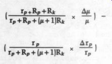
... where Ry is the cathode resistor, R,, is the plate resistor (same as R; ), R_p, is the anode internal resistance, R is the amplification factor, Au is the change in ux as a result of changing the anode current, and Ar, is the change in r, as a result of changing the anode current. In practice, Ar, is negative, so the two terms add together.
On page 470 of the Dover book, equation 102 suggests that distortion is %s of the fractional change of gain.
Assuming that the cartridge has a 5mV output at mid frequencies, say 1kHz, and 50mV at 20kHz (obviously this is dependent on the cartridge and the disk being played), the distortion of the cascode stage's lower tube anode is 0.03 percent for a 100mV output at 20kHz (gain is 6dB, R_load is approximately 1.1k, and I4 is approximately 3mA) and 0.003 percent for a 10mV output at 1kHz. For the top tube anode alone, the distortion is 0.014 per cent for a 2V output at 20kHz (gain is 31dB overall, R;04p is approximately 20k, and Ry is approximately 1.1k) and 0.0014 percent for a 200mV output at 1kHz. All these voltages are peak to peak.
As Christopher Paul observes in TAA 2/85 (p. 51), the distortion of the cascode stage's first section is relatively high because of the low value of its effective load resistance. This distortion is in creased further when the tube is run in such a way as to put the operating point at a high rate of change of both yx and r,, (anode internal resistance). Should the operating point be shifted to a lower rate of change (by running the tube at a higher current), the distortion products can be significantly reduced.
There is a point beyond which the rate of change of x and r, drops significantly.
For the 6DJ8, this is approximately 10mA per anode. That is to say, if R121 is 180k (still keeping the current through the cascode dependent on the bottom tube rather than the top) and the anode sup ply voltage is 350V, then I, is approximately equal to 6mA, at which point the distortion products for the lower tube anode become 0.01 percent for a 100mV output at 20kHz and 0.001 percent for a 10mV output at 1kHz. The distortion products for the top tube anode alone are 0.006 percent for a 2V output at 20kHz and 0.0006 percent for a 200mV output at 1kHz. As before, these are peak-to-peak voltages.
Similar considerations apply to other tubes in the circuit that are run at an anode current of approximately 4mA. At 350V, the tubes run at approximately 6mA. The effect of this is to reduce distortion products by a factor of approximately 2.
By raising the supply voltage, the tubes can run at a more linear part of their characteristic. Because the circuit topology is not changed, comparisons are justified. Unfortunately, I do not have a version of the Daniel preamp and so can not comment on the perceived nature of the changes. The changes themselves are relatively easy to implement, as they affect the power supply board and the wattage of R125 and R133. I realize that any circuit's sound is made of many different factors, and distortion is just one of them.
Perhaps Mr. Curcio could assess the impact of increasing the supply voltage.
A. Nehan London, England E18 2HE Mr. Curcio replies:
As Mr. Nehan notes, much of the p and I, modulation can be minimized by operating the circuitry at a higher static current, which can be accomplished by increasing the supply voltage. This was a question of great deliberation in the circuit design. In keeping with the single regulator reference/supply circuit (in the form of the LM317T floating regulator), I had to choose a compromise Vc operating point that could supply both a cascode and cascade circuit topology from the same level and at the same time not exceed the maximum ratings of the designated 6D]J8s in the cascade circuit.
The RCA tube manual is quite vague in specifying maximum values, stating that the maximum “plate supply voltage ” is 130V (design center values). This data, even when interpreted with the aid of RCA's terminology explanations, can be interpreted in two ways: the Ve. (B+) sup ply can be no greater than 130V (which I and others have clearly exceeded), or the plate voltage (Vp) should not exceed 130V.
I chose the latter interpretation.
Therefore, in operating the circuit at a Vee of 350V (and assuming an I, of 6mA per valve), the static plate voltage of the cascade stages will be approximately 110V. This operational point is still within a sufficient margin of safety, and I envision no problems in this mode. I do not at this time have the Daniel prototype at my disposal, so I am not in a position to confirm its effect on the sonics. I will, however, take this opportunity to suggest that your contribution extend beyond the mathematical into the audible, and I pro pose that you assemble a Daniel preamp upon which you can evaluate many of your suggestions.
DANIEL FEEDBACK
I HAVE A FEW questions and observations on J.J. Curcio's Daniel preamp (TAA 2/85, p. 7).
First, most regulators seem to require a high-value (greater than 10uF) capacitor from their output to ground to cur tail oscillations. I noted that Mr. Curcio's regulators (IC101 and Q101, among others) do not have such capacitors, which would be fitted from their emitters to ground. I wonder why he does not require such capacitors, and I presume that I would obtain no benefit from adding them.
Second, I noted that the collectors of these regulators are returned to a resistor rather than to a V,.. As the PSRR (power supply rejection ratio) of these devices is not infinite, surely the changing cur rent through the valves modulates the power supply voltage seen by the ICs, thus affecting their output. Would it not be preferable, at least in theory, to return the regulators' collectors directly to V.
I accept that the impact of the resistors is likely to be very small, approximately -90dB down at 10kHz.
Third, the data sheets suggest (and this fact is confirmed by my personal experience) that decoupling the adjustment pin of an LM317 with a 1 to 10xF capacitor reduces, by a factor of 20dB or so, the noise on the output pin, and I noted that Mr. Curcio has used such a capacitor on IC104. IC2, however, is without this type of capacitor, unless C8 performs that function, and I wonder why R10 was included, other than, perhaps, as turn-off surge protection.
Similarly, I wonder why R11 is shown in series with C9. I would be grateful for a short explanation of the purpose of these two resistors.
Finally, my amplifier is a Nelson Pass design that is connected to my preamp via four meter cables. The output impedance of V103 is (R, + uRx) in parallel
[...]
is practicable, with his design philosophy. (I see that low output i is priority 3 in his design considerations.) I imagine that I am not the only one with these requirements. What a tiresome lot we readers are!
A. Nenan London, England E18 2HE
I found J.J. Curcio's preamp intriguing and somewhat confusing: it took me half an hour to figure out the master power supply schematic. After rereading the article, several questions remain, and I hope Mr. Curcio can answer them.
gain.
for low-output moving coils, but seems to be rather high for line-level sources, which generally put out 0.5 to 2.0V RMS, whereas most amplifiers need 1 to 2V RME for full output. Thus a gain of 0 to 10dB or so would appear to be better suited and would allow you to use the volume control in the upper part of its range, where tracking between channels should be better. This would also work well with moving-magnet or high output moving-coil cartridges, which higher in voltage output than typical low-output moving coils.
Perhaps Mr. Curcio could alter native component values for a lower gain output stage.
I also have some questions about some of the parts values. Mr. Curcio made the somewhat enigmatic comment that his choice of RIAA equalization values 'will no doubt spark controversy.’ When I compared his values with calculated sold using the Lipshitz article on RIAA networks […] Volume 27, Number 6, June 1979), 1 found significant discrepancies.
Specifically, leaving C111=3300pF, R122 =663k0, R123=96.4k0 and C112-C114 combined should add up to 1132pF, assuming that the output impedance of V101 is zero and the input impedance of the next stage is infinite.
Taking into account the non-zero out put impedance of the first stage and the capacitance of the second phono stage, I think R122 should be slightly lower than calculated and the combination of 56 The Audio Amateur C112-C114 should also be slightly lower. I also think the capacitors could be polystyrene, which are available in 2.5 percent tolerances, rather than polypropylene, which are usually available only in 10 percent tolerances.
An additional question arises from his use of a 0.47uF output cap for the high level section. This seems to be a bit small, as he also states that the circuit can drive an input impedance of 20k, which combined with the capacitor gives a -- 3dB point of 17Hz. 1 think a capacitor […] be better. Inciden […] , as long as I am on the subject, what is the output impedance of the high-level stage? This would be a useful piece of information for anyone contemplating using long output cables.
Finally, I noted the use of carbon resistors in the signal path (e.g., R114, 127, 128 and 130) and wonder why they are used instead of metal film resistors.
On a more general subject, TAA has published several brief notes on suppression of turn-on and turn-off thumps, and it seems to me that any thoroughly engineered preamp (or amp) should include such suppression. Muting switches are inadequate because they do not protect against sudden power failure, nor do they protect against Murphy's law, which says that someone, sometime is going to forget to use the switch or leave it in the wrong position. Interestingly, one designer has suggested that such turn-on and turn-off noises are indications of DC instability in a circuit or power supply. He claims that his designs are free of such instabilities and there fore thump-free. I would be interested in Mr. Curcio's (or anyone else's) comments on this subject.
James Lin West Haven, CT 06516
Mr. Curcio replies:
a suitable the readers who have written to express an interest in Daniel. Since many of these questions are repetitive, I will at tempt to answer those that are most recurrent.
1. The regulator. The output capacitor employed in many of the high voltage regulators I have measured and auditioned is necessary to reduce the circuit's tendency toward oscillation. My measurements have shown that al though static stability may be achieved to transient loading is oscillatory. I have come to the conclusion that this behavior has major sonic implications.
I have included the R103/C102/C103 network surrounding each slave to en sure static and dynamic stability. As a result, in this design and in the pre preamp circuit (TAA 5/84, p. 7), you will note the absence of an output capacitor requirement. I think the minor modulation of the PSRR is acceptable in exchange for this stability. Returning the collector of the series pass transistors to the V.. point would virtually eliminate this modulation, but I have not had the opportunity to test the response of this configuration to transient loading and therefore cannot testify to its stability. (The prototype is not currently at my disposal, but stay tuned.) Please note that in the pre-preamp circuit, this filter circuitry provides both the controlled modulation of the PSRR and stability insurance. In the preamp circuit, however, this network serves only to ensure stability and actually sacrifices PSRR modulation. The dual purpose scheme was not successful in the multi-slave design.
Regarding the master regulator, full credit for the design belongs to Michael Maida of National Semiconductor. My circuit is virtually identical (with minor alterations) to that published in the 1982 National Semiconductor Voltage Regulator Handbook (p. 7-34). I also used it in my pre-preamp circuit and noted it in the references there. Its operation, fully explained in that article, is as Mr. Nehan surmises.
2. Output impedance. The output impedance of the phono and high-level stages is, as Mr. Nehan has calculated, approximately 5k ohm. I acknowledge that this might present a problem to those using low input impedance (20k) power amplifiers. Since I am a valve devotee, my empathy is limited, but that is not the point. When and where possible, I suggest that you attempt to increase the input impedance of the associated power amplifier. Many times, the input impedance is determined by a dominant loading resistor rather than the circuit itself. In those circumstances where this is not the case or is otherwise impossible, you may take advantage of the dual paralleled triodes in this design and with minimal effort, modify the circuit to the design illustrated in Fig. 1.
As mentioned in the article, I have little affection for the single supply cathode follower, and with a little extra effort (in circuit trace surgery and additional component location problems), some of you may wish to use the circuit topology suggested by Christopher Paul in TAA 1/85, p- 51. The component values necessary for a bias current of 10mA at a V.. of 250V...
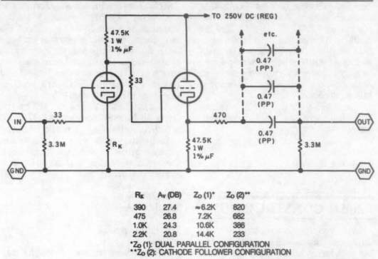
FIGURE 1: This power supply modification for the Daniel preamp will increase
the input impedance.
...are shown in Fig. 2. I have made a prototype of this circuit and have measured a Z_ow of 350 ohm with a gain of 29dB (com pared to the 5k ohm/27dB of the original design). Measurements for different values of Rx are shown in the table accompanying Fig. 2. One note of caution: neither Mr. Paul nor I have auditioned this circuit in the amplification chain and will not, at this time, endorse its sonic performance.
3. High-level gain. I chose the gain of the published high-level circuit to complement the phono stage's lower than conventional gain and ultimately to result in a unit with moving-coil capacity employing minimal signal processing (gain blocks). Should Mr. Lin's reason for lowering the gain be a change in potentiometer tracking, I suggest replacing this pot with a higher quality unit. (Try the 100k Alps units from Old Colony, PO Box 243, Peter borough, NH 03458). I have indicated several possible gain-reduction biasing arrangements in the table accompanying Fig. 1. Note that in selecting this method of gain reduction, it becomes necessary to use the cathode follower to maintain an acceptably low Z_ou.
4. RIAA. Virtually every preamp article in TAA has elicited some sort of response concerning the RIAA components. Assuming this article would not break tradition, I submitted my remarks to absolve myself from any deliberate wrongdoing in this regard. I calculated the published values with regard to the loading of the cascode's first stage, the network loading of the following stage and the realization of a network from standard component values. The resultant prototype (constructed from random 10 percent capacitors) deviated no more than 0.2dB from the “standard ” RIAA curve (Fig. 3).
For those who demand higher precision, I suggest hand-selecting the capacitors rather than changing to another dielectric. If you wish to calculate your own network, the Zou: of the first stage is 18.6 k-ohm .
5. Output R/C network. Many of you recognize that resistors, as well as capacitors, contribute to the final sonic result. In this application, I have used the sonic fingerprint of carbon resistors to compensate for an upper-midrange glare I find objectionable in the 6DJ8/WonderCap combination. I am sure you realize this is purely subjective, and you may wish to experiment with the effect. I suspect, but have not yet confirmed, that the resistors might sup press the overshoot and ringing resulting from pulse-like inputs.
The value of the output coupling capacitor was the result of the philosophy expounded in the pre-preamp article, in which I expressed my reservations concerning large-value (greater than 1uF) coupling capacitors. Specifically, I find that they impart an un natural heaviness on the audio signal being processed. In those circumstances requiring a larger value, you can minimize this effect by building the minimum value necessary with paralleled combinations of smaller values.
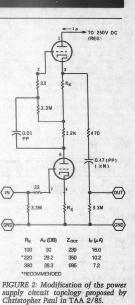
FIGURE 2: Modification of the power supply circuit topology proposed by Christopher Paul in TAA 2/85.
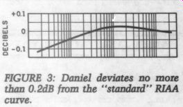
FIGURE 3: Daniel deviates no more than 0.2dB from the “standard ” RIAA curve.
For example, should you require minimally 2.0uF, parallel four 0.47 units.
6. Turn on/off output muting. I agree completely with Mr. Lin. Initially, I had planned on “completing ” the design with auto muting, but time proved to be my master. I recommend that those of you who are so inclined build the functionally equivalent circuit suggested by Mr. Nitikman in the Audio Aids section of TAA 1/84 (p. 39).
7. Corrections and omissions. The Motorola optocoupler shown in the text and parts list was incorrectly specified as an MOC4030. The correct device is MOC3040. If you have trouble this device, you may substitute the Motorola MOC3030 or MOC3031, which has a slightly lower but still acceptable AC voltage rating.
Circuit Specialists ( PO Box 3047, Scotts dale, AZ 85257) stocks the MOC3031.
Please be careful with substitutions, as these are zero voltage crossing devices.
In addition, a number of readers have had difficulty obtaining the Midex relay specified. You may substitute almost any four-pole, 5A (contact rating) relay with a 110V AC coil. Be sensible here and avoid motor starters.
TUBE TESTER WANTED
I need some tips for tube testing. I have all tube equipment: ARC SP6A and SP10 preamps; a pair of MC 275s (MacIntosh Tube God Mods); a Marantz 10B tuner; and a Counterpoint S2A head amp. It is very difficult to find decent tube testers today; most parts stores do not even carry them. I think it would be more practical for me to have my own. I hope someone can recommend a device that suits my needs and is reasonably priced.
I would consider a more […] model if I could find one secondhand.
Nick DeSterano; Paramus, NJ 07652
Try Fair Radio Sales, PO Box 1105, Lima, OH 45802.
They have used military tube testers for $100 or so.-Ed.
AMBISONIC ACCOLADES
Thank you very much for Bill Sommerwerck's series on Ambisonics (TAA 3/84, 4/84, 5/84). 1 have been making B format Ambisonic tapes for the past year and a half and am now assembling a planar decode system. I must qualify as a fanatic: I actually bought a Soundfield , which, by the way, is about $3,000 less than Mr. Sommerwerck states in his article.
Judging from articles in TAA and Stereophile, as well as in the British press, a growing number of people are seeing (and hearing) the advantages of the Ambisonic system. As J. Gordon Holt put it in a recent issue of Stereophile, you eventually reach the point where it is unacceptable to have all the sound emerge from at most one quarter of the acoustic space.
As you probably know, IMF Electronics was going to begin importing the Minim magazine.
[…] you Sully, and you do it very well.
Ruby CHALUPA; Evanston, IL 60202
SMD CONSTRUCTION
A new construction technique using surface-mounted devices (SMDs) is gaining popularity in the electronics com munity because it offers far more parts per square inch and thus lower product cost. SMDs are very tiny, and just about any electrical component can be had in an SMD package. The new pocket stereos, and I am sure the new Sony Diskman, owe their size to SMDs. For an example of SMDs, I refer you to the Cincinnati Microwave ad in recent automobile magazines. The new Passport radar detector uses SMDs, and the company points this out in the ad with good photos and descriptions.
SMDs have no leads and are held to the board by a small drop of glue prior to soldering. They are very tiny (about 3/8 inch square), and putting SMDs on both sides of double-sided boards results in a thinner overall assembly than “standard ” techniques. In addition, they do not require you to drill lead holes. The big drawback is that they are impossible to put into mass production without special automated equipment, as they are difficult to solder by hand.
My question is this: how do they com pare sonically? If they sound better, should we switch to SMDs in future projects, or are they too costly, hard to find and difficult to use? Can you get metal film SMD resistors or polystyrene SMD capacitors? Do the lack of leads and shorter foil traces contribute to better sound versus otherwise identical leaded components? Perhaps TAA could do a comparison.
For instance, you could take a tried and true TAA project, such as the William son preamp or the Pass power amp, and construct an identical version on a new, smaller board using SMDs wherever possible. Then invite several outside observers to do double-blind comparisons and report their findings. You could possibly build several units using SMDs from various manufacturers to determine whether there are sonic differences between SMD types (as I am sure there must be, given past findings with leaded components). If not you, then perhaps one of the audio societies might take this on as a club project and report the results here. Are you interested, Mr. Carlstrom? As a side note, I am confused by the letter on MOSFET tests (TAA 3/85, p. 55). Are you saying that the returned Hitachi MOSFETs were okay, but the wrong voltmeter was used to check them? Or were they bad, and this is a further clarification?
Rick Downer; Seattle, WA 98103
The Editor replies:
We do not have the staff to do the sort of basic research Mr. Downer suggests.
Readers with access to a supply of SMDs are welcome to submit results of double blind or subjective tests. I have yet to see any individual components available in SMD form and would be very surprised to find any very high quality caps or resistors in that form. I also cannot imagine retail mail-order vendors that sell to individuals stocking such items for hand assembly.
As for Mr. Downer's question about the MOSFETs, they were fine. The voltmeter's leads were unspecified and gave misleading results. If you use an ohmmeter to test MOSFETs, use one with a low-ohms capability or check the voltage polarity on the voltmeter leads.
TAPE-DECK TECHNOLOGY
I would LIKE TO see an article on updated tape-deck electronics, particularly concerning the playback mode. I have a solid-state Sony tape deck, which would not require much updating. I also have a Webcor unit with tube electronics, however, which would require quite a few changes. All that would be needed for playback would be the electronics for the heads to the auxiliary input to my system's preamp.
Robert B. JENSEN; Reading, PA 19601
The Editor replies:
See Daniel Meyer's “A Super Op Amp Preamp ” in TAA 1/72 for a circuit that configures for tape heads and works well.
AD
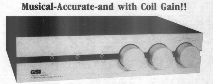
Musical-Accurate-and with Coil Gain!! GSI quite proudly presents the Stp preamp. Featuring a computer optimized high current tube audio circuit, advanced 7-stage regulated and active-buffered power supply, metal-films, custom non-inductive wire wound plate-load resistors, polypropylene audio caps, glass epoxy board, .5dB RIAA accuracy, milled aluminum faceplate, all steel cabinet, gold input and out put jacks, external phono load jacks. Unit has automatic turn on/off mute, 5 year transferable warranty.
Max Output: 65V; Line Gain: 34dB; Phono Gain: 40dB; S/N ref 10mV, -88dB; Frequency Response: 20k + 400pF, load =.3dB, 3Hz to 250K; Tubes: (2) 6DJ8, (2) 12AX7, (1) 12AT7; Retail: $1095.
Dealers include: Esoteric Sound, Stony Brook, NY; The Audio Dr., Buffalo, MO; Audio Classics, Oklahoma City, OK; D.K. Smith Audio, Pittsburgh, PA; AudioVision, Lexington, MA; Crosbys, Hobbs, NM; RSN Assoc., High Point, NC.
Just Looking
Audio-Technica's first compact disk player, the AT-CD10, features triple laser tracking, double-resolution digital filtering, […] random […] and a multifunction indicator. The heart of the AT-CD10 is its two large-scale integrated (LSI) circuits, which do the work of many complex IC chips and discrete components. As a result, the player offers a number of user conveniences and compactness at a moderate price.
Through its triple-beam laser tracking, the AT-CDI10 is said to offer high tracking precision that eliminates distortion caused by pickup of spurious data. A double-resolution digital filter uses a sampling rate of 88.2kHz, twice the rate of conventional players. This filtering design incorporates a “de-glitcher ” sample-and-hold circuit and a simplified, low-angle analog filter that cuts phase shift, noise and distortion.
The AT-CDI10 allows the user to pro gram, for playback, nine randomly selected tracks from the disk and also features an independent stereophone volume control, making it usable as a stand-alone CD stereo system.
Information is available from Audio Technica, 1221 Commerce Drive, Stow, OH 44224.
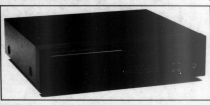
The NEC AV-300E is a four-channel power amplifier (30W by four channels or 60W by two channels) that simultaneously serves as a control center for sophisticated audio/video systems. In addition to its integrated power amplifications, the AV-300E provides full Analog Systems has announced its new series of + 22V JFET op amps. A single op amp, the MA-333, and a dual op amp, e MA336, are both available in 8-pin metal can (-CH) or 8-pin plastic DIP (-CP) packaging. The quad MA-374-CP comes in a 14-pin plastic DIP.
These op amps feature the highest operating voltage rating available, low noise, low distortion and unity gain stability. All are tested before shipping and have guaranteed noise specifications. They have standard pin-outs for retrofitting existing equipment and upgrading production boards without any change in circuit-board layout.
For more details, contact Analog Systems, PO Box 35879, Tucson, AZ 85740.
... video switching (four video inputs/out puts in addition to one monitor output) and audio and video signal processing.
Most important among these facilities is the AV-300E's three types of surround effects: Dolby surround for Dolby surround or stereo encoded video software; hall surround for movie theater effects especially suitable for mono software; matrix surround to produce special effects from conventional stereo softening, especially suitable for action-type programming.
In addition to these surround effects, the AV-300E can create simulated stereo from mono signals and can eliminate tape hiss from poorly recorded programs via its high filter. Picture quality can be improved with the AV-300E three position image enhancer. The unit also features a 20-function wireless remote control, which provides for adjustment of the surround effect, volume, balance and even VCR tape function with NEC or suitably equipped machines.
Write to NEC Home Electronics, 1401 Estes Ave., Elk Grove Village, IL 60007, for details.
The TIA-3012A is the second generation of Tandberg's TIA-3012 integrated amplifier. The new unit employs rugged, fast MOSFET output devices operating in conjunction with a high current power supply with zero feedback to provide a power output of 100W/ channel into 8Q from 20Hz to 20kHz with less than 0.02 percent distortion.
The current potential of each channel is 30A, ensuring against current limiting.
Special features retained from the earlier model include the use of selected, discrete components (instead of ICs) in all active circuits, full protection against overload damage without the use of cur rent-limiting circuits, and a dedicated digital disk input that operates without signal-path capacitors and with a signal overload headroom of more than 20V.
In addition, the new TIA-3012A has an enhanced power supply and output circuitry for a capacity of 30A per channel; separate stabilized current supplies for the small-signal and output stages; redesigned low-impedance tone control circuits; newly developed polycarbonate signal-path capacitors whose dielectric characteristics eliminate any trace of “signal-memory ” smear; and a re vamped circuit-board design. A number of subtle circuit design improvements, such as the elimination of frequency corrective feedback capacitors, contribute to the enhanced performance and musicality of the TIA-3012A.
Further details are available from Tandberg of America, Labriola Court, PO Box 58, Armonk, NY 10504.
Four low-loss interconnect audio/video cables and two connectors for joining cables or adapting them to associated equipment have been added to the Signet product line. All cables feature a Litz wire conductor, which reduces high-frequency losses by enlarging the conductive area. The conductor, made of 55 strands of 0.12mm oxygen-free copper (OFC), is covered with a heavy foam dielectric layer. This, in turn, is doubly shielded by conductive polypropylene and braided copper. The shielding prevents pickup of hum and stray radio-frequency (RF) energy. A highly flexible outer jacket protects the inner structure.
The VK412 three-piece audio/video cable set includes a pair of 5mm diameter audio cables and a single 8.5mm diameter video cable, all terminated in RCA-type connectors. The cable's primary function is to connect the outputs of a stereo VCR to the inputs of a stereo audio system and the video input on a video monitor or TV.
Two Signet VK411 video cables are also available. Both are terminated in gold-plated quick-disconnect male F type connectors. Completing the line of interconnect products are two gold plated connectors, the VK422, used to join two quick-disconnect male F connectors, and the VK421, which joins two RCA male plugs.
For additional information, contact Signet, 4701 Hudson Drive, Stow, OH 44224.
----
Also see:
PREEMINENT PHONO PREAMP, By John H. Roberts
UPDATING PULSE MODULATION, By Norman Crowhurst