UPDATING PULSE MODULATION
In 1966, I was issued a patent for a form of pulse modulation that promised to revolutionize audio, and perhaps other fields as well. As with highly-efficient carburetors that have been squelched, however, my development was stopped cold. My circuit used germanium transistors because silicon types were still too expensive.
The test results, however, were phenomenal if not unbelievable.
Advantages I had two memorable demonstrations. In the first, a small unit, run from ten C-size rechargeable cells, supplied sound to a noisy sporting event where no electric power was available. It operated all day, recharged overnight, then performed another day's work. One onlooker suspected I was using a concealed supply from the nearest electrical outlet.
In the other demonstration, I showed the same unit to a police department. I installed the unit under the dash where it provided both siren and voice power. We cruised along a coastal highway to a point where a straight stretch, with a dip in the middle, extended about two miles.
As we entered one end, we saw a cyclist enter at the other, riding with “no hands. ” I picked up the mike and said, “Hands on the handlebars, there.” About ten seconds later--the time it took for the sound to travel that far--the boy grabbed his handlebars.
The cop looked at me and smiled.
Voice units on police cars had difficulty reaching 100 feet, much less 10,000 feet. Even at 100 feet, intelligibility wasn't good, so I knew I had something valuable.
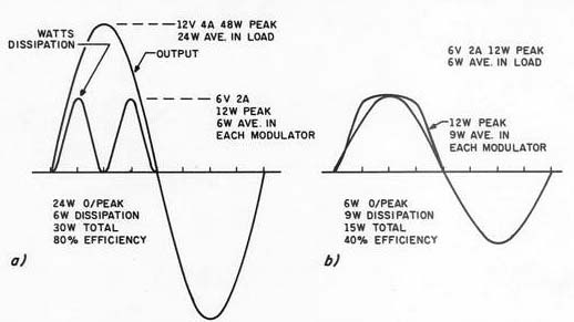
FIGURE 1: Deriving the efficiency of an output circuit using Class B.
1a shows a sine wave of maximum amplitude, while 1b is at half-amplitude
(6dB below maximum).
Stone-walled
The invention, however, never bore fruit. Several companies, after reading about the patent, inquired about put ting it into production. For some reason, however, none of the inquiries materialized. Emergency vehicle voice systems are only slightly better than when I tested my unit 20 years ago. In fact, high-power audio, in any application, is very inefficient. Let's see why.
Basis For Efficiency
In tube days, the most efficient audio power output in general use was called Class B. Now, solid-state parts are used instead. Figure 1 shows why Class B's efficiency is so limited. A sine wave representative of a full out put is shown in Fig. 1a.
At peak, let's say the load receives 48W from a combination of 12V at 4A. (I use these convenient figures by way of example.) The power magnitude does not alter the proportions.
On a sine wave, 48W peak power will be an average power of 24W.
For each half-wave, the modulator device-be it tube or solid-state-will dissipate the most power at half voltage and half-current. 6V at 2A will give a peak output device dissipation of 12W, or 6W average, for each half-wave. The other output device, handling the other half-wave, will also dissipate an average of 6W during its half-wave.
The total output stage dissipation is 6W, split in time between the two tubes, solid-state devices, or what ever. So, to get 24W output, the out put stage must dissipate a further 6W, requiring a total of 30W from the supply. This would be an 80% efficiency at maximum output. Remember, these numbers are purely hypothetical. Actual output stages may not do as well.
As any audiophile knows, audio doesn't consist of a constant, maximum output sine wave. Fig. 1b shows what happens to a half-amplitude sine wave with half-voltage at half-current in the output load. This is 6dB below maximum. At this level, 6V at 2A makes 12W peak, a 6W average.
Maximum output stage dissipation now occurs at maximum voltage and current in the load because this is half of the available maximum. Under this condition, the output stage dissipation averages % of its maximum, so each output tube or solid-state device dissipates an average of 9W during its operative half-cycle. The complete stage dissipates IW. 6W output with 9W dissipation represents an efficiency of only 40%. Maximum output stage dissipation occurs at this level, but the efficiency be comes still lower at lower levels.
More than 20 years ago, several engineers, including myself, realized pulse width modulation could achieve higher efficiency. In this form, the output stages, be they tubes or solid state, would spend most of their time either on or off.
In pulse width modulation, the transition from off to on, and vice versa, is very fast. The required inter mediate fluctuations of audio frequency are accommodated by varying the relative duration of 'on' and “off ” times at this ultrasonic frequency. The switching frequency is easily filtered out (as are radio frequencies in radio reception) in the feed to the output load.
When the device is “on,” its volt age drop is close to zero and its cur rent is high. When it is 'off,' the full supply voltage is across it, but it carries no current. Both states represent zero power. In the extremely short time during which it switches from off to on, and vice versa, maximum dissipation occurs the instant voltage and current are each half-way.
That occupies only a fraction of a microsecond, at intervals of several microseconds. Clearly, at maximum output, such a device can far exceed Class B's 80% maximum. It can achieve this efficiency whatever the momentary audio level.
At any level throughout either a maximum waveform or at lesser ...
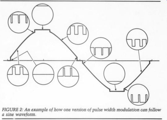
Fig 2
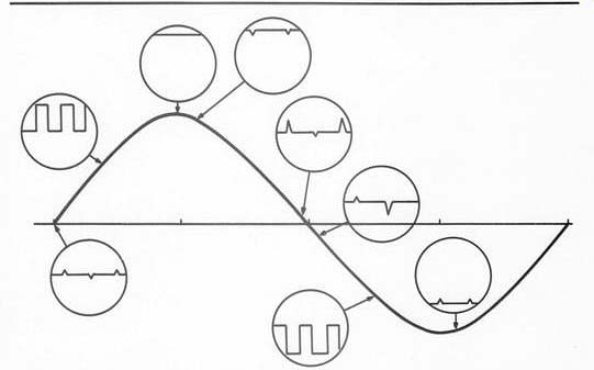
FIGURE 3: The author's pulse modulation improvement earned him a patent
in 1966.
... magnitudes, the output stages operate as switches: they are always either “on” or “off.” Nearly all the energy at all levels goes into the output load. The measured efficiency of those prototypes from 20 years ago was well over 95%.
That is why ten C-sized batteries could provide such apparently enormous power all day without going flat. A Class B circuit, meanwhile, would have flattened the battery in a few minutes.
Overcoming A Flaw
Simple pulse width modulation has a disadvantage that is particularly ob noxious on audio (illustrated in Fig. 2). Because it switches so rapidly, it either switches or it doesn't. At one point, a discontinuity appears in the reproduced waveform. At both zero crossover points, and approaching maximum in either direction, there is a “step ” where pulses suddenly start or stop.
My patent circumvented this flaw by introducing pulse amplitude modulation at lower levels, whether on a big or small waveform. This removed the obnoxious feature, as shown in Fig. 3. In the quiescent state, the circuit adjusted itself until tiny spikes alternated on either side of the center line. The spikes' frequency is ultrasonic, so they can't be heard.
For the moment, accept my word that this can be done. Soon, I'll explain how my patented circuit works, and how you can “translate ” it to use solid-state chip technology. First, let's continue to see how my patent overcame the flaw.
Low level signals, or the crossover points on bigger waveforms, were handled by increasing the size of the spike on one side and reducing them on the other until the side where they increased reached full height. Then, width modulation took over until maximum power was delivered to the load.
Carefully think through this process again if you didn't follow the idea the first time.
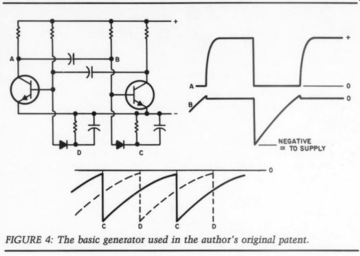
FIGURE 4: The basic generator used in the author's original patent.
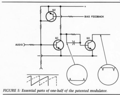
FIGURE 5: Essential parts of one-half of the patented modulator.
Original Circuit
How can this work? My original patent used a multivibrator to generate the control or switching frequency (Fig. 4). In those days, such things as op amps or flip-flops were in their in fancy and very expensive, so it was cheaper to use older technology.
At each collector, such a multi vibrator generates an approximate square wave. At each base, it generates waveform B. Using a diode and capacitor with a discharge resistor produces interlaced sawteeth, represented at C and D. Now, look at one side of a push-pull type output stage (Fig. 5). Three sources feed transistor Q1's base: bias current from the top (to keep it fully conducting until switched off), the sawtooth current from below, and a current from the left representing the audio waveform.
Q2 provides feedback to automatically control Q1 bias so that, in its quiescent condition, it will produce the requisite-sized spikes. Q1 is on all the time, but produces tiny spikes in quiescence. When it amplifies its half of the audio waveform, those spikes grow to full amplitude and then spread in width modulation. Q3 merely inverts the signal at Q2's collector. Q3 is, therefore, normally ‘off’ except for the spikes or the modulated audio for its half of the waveform.
These were the guts of the successful circuit I designed more than 20 years ago. Today, germanium transistors are all but obsolete, and nobody uses discrete silicons if they can avoid it. Therefore, we need to update this idea, using less expensive devices.
Modern “Translation”
The type of multivibrator I used is no longer available, but you can use any opamp--plenty of types are available--as a multivibrator. The advantage of an opamp is it simultaneously produces square and triangular waveforms (Fig. 6). The triangular waveform normally appears at the multivibrator op amp's negative or inverted input.
To stabilize this triangular wave form, which appears at a very high impedance point, the other opamp acts as a “follower” to provide the same voltage waveform at very low impedance. Use a couple of capacitors and suitable biasing (which I'll come back to) to “separate” the same waveform into two duplicate shapes so the voltage at the bottom of one is nearly the same as the voltage at the top of the other.
Feed these triangular waveforms to further op-amps (not shown) at one input of each while feeding audio to the other. These op amps can then perform the same switching function shown in Fig. 5. Before you get started, however, you need to know whether you can adequately control the output from the generator op-amp.
Which Is Best?
In op amp technology, we encounter slew rate, a value we didn't have in tube technology. It is roughly equivalent to high-frequency cutoff, but it has rather different dimensions (Fig. 7). Slew rate controls the time taken by an op amp to switch from off to on at maximum speed, or vice versa.
For example, if you use a 741 op amp (a work-horse), it has a comparatively slow slew rate. Figure 8 shows what will happen if you use a 741 at the kind of frequency we need. The slew rate is so slow, it will take half a cycle to go up, and the other half to go down. What was a square wave in Fig. 6 becomes triangular, while what was triangular in Fig. 6 looks more like a sine wave.
Can you use a 741 or equivalent? Let's consider two factors. In the circuit in Fig. 6, the tri wave exhibits slight curvature of the “sides.” A 741 operating at its slew rate has the advantage of straighter sides, but it has a negative aspect, too.
Slew rate may not be the same going “up” and coming 'down.' More importantly, when the two slew rates meet, the height of the output wave reduces to eliminate the horizontal parts--which were the top and bottom of the square wave--because each action does not last long enough for the slew rate to accomplish a complete transition before it reverses direction again.
Using an op amp with a slew rate of many volts per microsecond enables you to use the circuit in Fig. 6, which will produce a more reliable waveform.
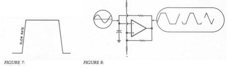
FIGURE 7: The meaning of slew rate, with reference to a square wave output.
FIGURE 8: When an op amp, such as the 741, has an excessively long slew rate, the tops and bottoms of the square disappear, and what was a square wave becomes triangular.
In coming issues, I will explain how to use this waveform for the completion of our project. Maybe you'll want to start working on it by yourself. It's a fascinating study.
Where Now?
As with any project such as this, being successful depends on knowing what you are doing. That's why this article is moving slowly and carefully. If you decide to pick up the ball from here and carry it further, please let me know how you fare. I'd like to know if you encounter difficulties, or if you are successful. Address your correspondence to PO Box 63, Dallas, OR 97338.
In Part II, Mr. Crowhurst will explain how to make an updated pulse modulated amplifier.
ABOUT THE AUTHOR: Born in England, Norman Crowhurst graduated from London University as an electronic engineer in 1935. He was chief engineer of Tannoy for many years, and held two part time professorships with London University before World War II. In 1953, Mr. Crowhurst emigrated to America where his career flourished. He earned awards in engineering, publishing and education, and has several patents in his name. In 1967, he retired from engineering but has kept his interest in audio. Having seen the American industry fall behind, he is now seeking to reactivate his career.
----
Also see:
DECCA RECORDS MONTREAL'S PETRUSHKA, By The Editor
PREEMINENT PHONO PREAMP, By John H. Roberts