POOGE-3
THIS ARTICLE ON POOGE-3 shows how improving common-mode and power-supply rejection can improve the audible performance of your amplifier. I have used concepts on which a vastly more refined commercial amplifier (Moraga Series 935/936, 962) was based. Instead of just telling you what I think you ought to do and how you should do it, I will also describe the basic philosophy behind the procedure.
Retrospective
Several articles previously published in TAA and Audio (see references) have presented refinements for applications-oriented designers, DIY audiophiles and audio enthusiasts in general. Among these are articles on capacitors, preamplifiers, servo and direct-coupled amplifiers, power supplies, pre-preamps, grounding and low-Z wiring.
Although some of the information presented in these articles had been explored in relation to fields such as computers, communications electronics, precision measurements and metallurgy, its significance for audio was not known, appreciated or under stood. Applying these concepts to audio generated much discussion and criticism. Since that time, however, manufacturers have used these principles in new products and updates of equipment already on the market.
Most have been parts and power supply upgrades, which have generally received favorable reviews.
Until the latter part of the 1970s, audio components and systems were not of sufficient quality for listeners to recognize, with any certainty, many of the details that careful listeners now hear. No wonder “simplistic ” notions such as double-blind listening tests were hailed as the definitive indicator of sound reproduction quality.
By 1975, I had developed some criteria concerning amplifier design and construction, and I later published some of these thoughts in TAA 3/80 ( “A Passively Equalized Phono Pre-amp,” p. 18) in the hope that audio designers would consider more than frequency response, total harmonic distortion (THD) and signal-to-noise (S/N) ratio. At that point, audio seemed very much like the auto industry: it continued to turn out the same old stuff year after year with very few substantive changes and an emphasis on cosmetics. I used a preamp as an example in the 3/80 article, but have since upgraded my phono and auxiliary/line amplifier.
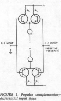
FIGURE 1: Popular complementary differential input stage.
Symmetry of Thought & Design
As with most subjects, there is a symmetry to audio design. The tendency is to modify or refine what you already have, but this limits the possibility of a better solution. If you think of an idea symmetrically--i.e., in its mirror-image or opposite state--the possibilities for advancement are much greater because you are able to consider everything be tween the extremes.
For example, if you learn that certain types of capacitors have non ideal characteristics that can be audible, the tendency is to find a more ideal type and substitute it. You refine the original design. The sym metrical approach would be to consider what would happen if you had no capacitor at all. This would force you to think of how you could make such a design work. Perhaps you could use a direct-coupled design (the best solution) or add direct-coupled/ servo circuitry to reduce drift and offset. With this approach, you can end up with a better, less expensive product than if you had refined the original idea.
Another example is power supplies. Some nice things, such as improved channel separation and better imaging, happen to the sound with added supply capacitance. Normally, our solution would be to build bigger capacitor storage banks. This gets ridiculously out of physical and monetary sight, so you might resort to electronic capacitance multipliers.
From there, it is a short step to the ultra-regulated supply, and the evolution continues.
It became clear to me that the power supply must approach the same level of sophistication as the amplifier, with diminishing returns.
The symmetrical approach was to design an amplifier that was immune to the effects of the non-ideal supply interface interactions.
Power Supply/ Amplifier Interactions
I have since found that the amplifying stage and its power source interact in certain ways. I discussed some overview of power supplies (TAA 3/83, p. 16).
Still, it is not recognized that you can reduce stage-to stage and channel-to-channel power supply effects in two basic ways First, [… ] immune to the effects of […] linearities.
In that case, a regulated supply is not (or at least is less) needed. I concentrated on how to improve the amp ckts to give it greater immunity to power supply problems.
For the lowest distortion potential, all amplifiers should be developed from balanced, symmetrical topologies. The best topologies are of the differential family, which consists of three basic amplifier types: push-pull, For the past decade, a popular vari […] differential input stage (Fig. > 8 serious shortcoming of this that the input circuit is not developed in any product with which I am familiar, except the JC-2 (1972).
John Curl not only used FETs, but also a complementary-differential in put stage in push-pull operation.
Without doing so, the upper pair could go off at a different slope than the lower pair (although matching devices reduces this problem). Just one resistor between the FET sources biases and dynamically balances both differential pairs.
Another popular topology is shown in Fig. 2a. This single-ended circuit is still used today (ARGH!). It is shown as a solid-state circuit, but many tube designs (especially pre amps) use it or a variation of it. I arranged it (Fig. 2b) with a complementary mirror image of itself to make it symmetrical (push-pull). One important limitation in tube designs is that there is no electrical complement to the tube. The dotted line in Fig 2b […] amp I used in my RIAA phono preamp. With only 15dB of overall negative feedback, the THD at 20kHz was 0.005 percent. I had to increase the output to 22V (p-p) just to be able to get off the test equipment residual of 0.0018 percent. At normal output levels (1 to 2V RMS), I could not measure the THD. Square-wave rise time was faster than my 0.05usec (50nsec) generator. How could this circuit be the weak link in my pre amp, and by what test was it weak? As usual, listening tests led me to further inquiry, where a straight-wire bypass clearly indicated some masking of inner detail.
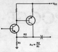
FIGURE 2a: The compound complementary
amplifier is still a popular topology.
Cascoding to the Rescue
It was not until I had gone off on a power-supply/amplifier interaction tangent that I came back to the line amp (and later the power amp) with some fresh thoughts. Earlier, I had tried a suggestion that I improve the bias method by using constant-current sources. I could not hear any improvement. After much thought about amplifier/supply interaction (TAA 3/83, p. 16), I tried cascoding the input transistors and heard a very noticeable improvement.
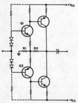
FIGURE 2b: The author's arrangement of the compound complementary amplifier
for symmetrical, or push-pull, operation. The dotted line indicates the
original bias method used for the prototype in his passive RIAA phono preamp.
I believe that the input stage of any amplifier must be a very linear, open loop design because this is where error-correction occurs. Cascoding In amplifiers that do not rely on poking negative feedback, this is an important technique. An additional benefit of cascoding is the reduction of distortion caused by gain variations with changing emitter-collector voltage.
The composite characteristic of a cascode stage is very linear. Because voltage variations across the transistor do not cause significant gain variations, the cascode stage can handle even large voltage swings with very low distortion. Practically speaking, each transistor in the cascode configuration does not have to hold off the full supply voltage. This allows greater freedom in transistor selection, especially in high-voltage (power) amplifiers. You may use lower voltage units, such as dual monolithic devices, for their superior matched characteristics. This is about as far as the textbooks go with the use of cascoding. If your design uses a lot of negative feedback, band width is high, and THD is low, you need not cascode. This is why cascoding has been seldom or selectively used.
Cascoding helps improve linearity by reducing distortion caused by the Miller “early voltage ” effect and ex tends the stage bandwidth. One benefit that is usually overlooked, even by those using cascoding for linearity and bandwidth reasons, is its improvement in common-mode rejection (CMR). CMR is important because variations of the power supply voltages can have the same apparent effect as a common-mode signal. The common-mode rejection ratio (CMRR) of the balanced or sym metric amplifier is zero. A nonzero CMRR is caused by asymmetry or imbalance in the elements that make up the amplifier. Research has shown that CMRR is limited by the open circuit voltage gain and fractional imbalance of these elements.
One advantage of the differential family is its tolerance of input common-mode voltage. For best rejection characteristics, the impedances seen by each transistor of the differential input must be the same, and their load impedances must also be equal.
For high frequencies, the differential stage loads can be trimmed for C imbalance. You may also apply a neutralization technique to the differential amplifiers to improve CMR and extend bandwidth.
By adding the cascode circuit (Fig. 3) to an amplifier of the popular complementary-differential input variety, I hoped to improve the common mode rejection, power-supply rejection and linearity of the error-correcting input stage. I was not concerned with increasing amplifier bandwidth or reducing the amplifier's already-low THD. I have found the improvement in overall performance to be greater and less expensive than with the use of regulated power supplies.
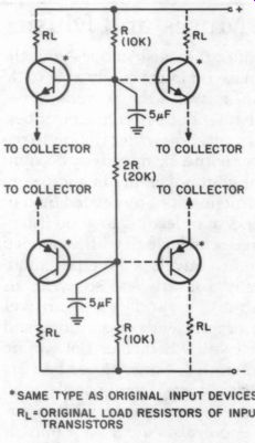
FIGURE 3: Mr. Marsh uses this arrangement to cascode the input stage.
With the added (dotted line) circuitry, this circuit may be used with any
complementary-differential input stage.
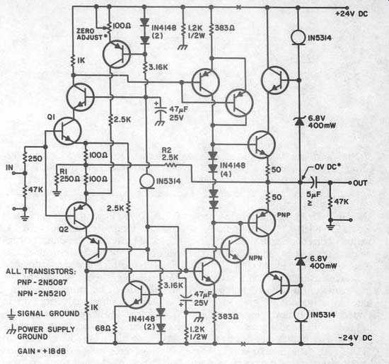
FIGURE 4: The author improved the CMRR and PSRR of his auxiliary/line
amplifier by adding cascoded input and output stages.
ALL TRANSISTORS:
PNP - 2N5087
NPN-2N5210
Circuit Mods
I have used the circuit in Fig. 3 with the David Hafler series of power amplifiers, but the same concepts apply to all amplifiers. If you own one of the Hafler amplifiers, simply lift the existing collector leads from the circuit board holes and add the cascode transistor collector leads to the holes. Then tie the cascode transistor bases together and attach them to the voltage divider resistors (10k and 20k junction). Tie the cascode emitters to each respective collector of the removed original input transistor.
Figure 4 shows the complete cascoded line amplifier circuit. I added the emitter-follower output stage for lower output impedance. This output stage is also cascoded. You may use the commonly available transistors shown (2N5210 and 2N5087). Optimally, you should try matching the devices using the method shown in TAA 1/82 (p. 7). If you own a digital multimeter, you may use it for the meter in the matching circuit. If you are not up to matching the devices yourself, use the MPQ6100 transistor array (if you can find it). It has two matched pairs of complementary devices per package (a 16-pin dual in line package). The current sources are 1N5314 (4.7mA). Otherwise, you can use a regular FET and resistor as shown in Fig. 5. Erno Borbely's article in TAA 5/83 (p. A various current source methods including the use of the LM334 him National Semiconductor).
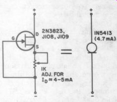
FIGURE 5: In Mr. Marsh's view, a suitable alternative to the 1N5314 constant
current diode is to make one from a FET and an adjust or select resistor
to establish an Ip approximately equal to 4 to 5mA.
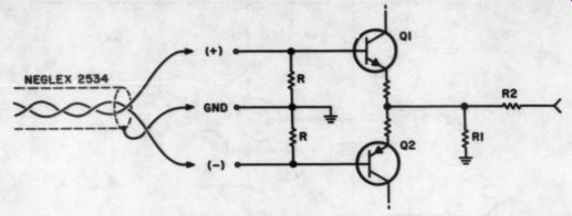
FIGURE 5b
Besides using metal film resistors (not carbon film), quality polypropylene capacitors (e.g., the Reliable Caps MF series) proper grounding techniques and a good supply (if you regulate it, a Sulzer supply from TAA 2/80, p. 8, is a good bet), the layout is not critical. Of course, if you need more drive current, you may substitute a TO-5 or a TO-220 device in the output stage and reduce its emitter resistors by the appropriate amount (perhaps to 10 to 200).
You may use the amplifier with any source requiring a moderate gain level increase. It will accept single ended or balanced sources (Fig. 6). By increasing R1, you can make an X1 isolation or buffer amp. Increasing R2 will increase gain. You may also change other values to alter various parameters. The values shown will, […].
I made the following traditional measurements without selecting or (R1 AC bypassed) is 40dB, and the open-loop bandwidth at -1dB is 150kHz. The open-loop harmonics are second and third, --82dB and - 85dB, respectively. These levels of harmonics translate into a THD of about 0.0007 percent for an X10 amplifier. You should, however, expect typical THD figures of 0.005 percent at 1 to 2V RMS due to device variations. Not too shabby for a low-feed back design. The closed-loop band gg is - 1dB at 560kHz. The S/N -85dB, unweighted, referred to 0dBm (0.775V), with a gain of 18dB and the input terminated with 1k.
The idle current is 4mA per device. For the lowest noise, this is a bit too high for these devices.
Nevertheless, the noise is quite low and the slew rate quite high.
With the additional attention to CMRR and PSRR (power-supply rejection ratio) characteristics, a versatile gain block is provided that not only measures well, but also sounds good. You might use the circuit in compact disk players, tape recorders, tuners, mixing consoles, filters and, of course, preamp auxiliary/ line amplifiers.
Unfortunately, advertising plays a major role in audio equipment design and popularity. My all-time favorite advertising myth, which has become accepted truth, is that the simpler the amplifier circuit is, the better. Advertisements also emphasize THD, IMD (intermodulation dist.), frequency response, S/N and damping factor, but these figures do not completely explain the audible differences. You must take into account other amplifier factors that are not generally stated in the specifications, but that have a significant effect on audio quality. You must consider two parameters in particular-PSRR and CMRR. Cascoding improves both at very little . I look forward to considerable improvement in these areas in future audio design.
ABOUT THE AUTHOR: Richard Marsh has been listening to music and building his own audio equipment since he was a child. Since then he has covered a broad range of audio activities. His recent interest in passive components culminated in a new capacitor design for which a patent is Mr. Marsh is employed at the University of California at Berkeley's Lawrence Liver more National Laboratory as a senior technical coordinator for fusion energy systems.
REFERENCES
1. Hollander, Chuck and Walt Jung, “Modifying the Marantz 7C or St. Pooge and the DRIAAGON, ” TAA 1/81, p. 20.
2. Jung, Walt and Dave White, PAT-5/WJ-1A: A PAT-5 WJ-1 Update, ” 3/79, p. 24.
3. Jung, Walter G. and Richard Marsh, “Picking Capacitors, ” Audio, February 1980, p- 52; March 1980, p. 50.
4. Jung, Walt and Dick Marsh, “POOGE-2” TAA 4/81, p. 7.
5. Marsh, Richard N., “Capacitor Fidelity ” TAA 4/77, p. 46.
6. Marsh, Richard N., 'A Passively Equalized Phono Preamp, ” TAA 3/80, p. 18.
7. Marsh, R.N., 'Dielectric Absorption in Capacitors,' TAA 4/80, p. 31.
8. Marsh, R.N., “A Pre-Preamp for Moving Coil Cartridges,” TAA 1/82, p. 7.
9. Marsh, R.N., “Power Up: An Overview of Power Supply Considerations,” "TAA 3/83, p- 16."
----------------
Muses and Music
Since the music moves you, the muse is almost surely able to do so as well-the writer's muse, that is. Put pen to paper or better yet, typewriter ribbon to pa per with a clear, orderly account of your adventure in audio construction, or any related field of endeavor leading to good listening. Send it along with a stamped return envelope. We pay modestly for articles, so write us about it and we'll answer promptly with suggestions and tell you whether or not we are interested. Some of our best articles come from people who have never before written for periodicals. And if your muse is as silent as a tomb, don't let that stop you. Write anyway and let's see what develops. We have a nice sheet of suggestions for authors which we will send to nearly anybody who asks for it.
------------------------
BY R.N.Marsh.
----
Also see:
PREEMINENT PHONO PREAMP, By John H. Roberts