TRUE THREE-CHANNEL FOR STEREO
AT ONE TIME OR ANOTHER, most of you have probably toyed with the idea of having more than two sound channels in your home stereo system. For anyone who has enjoyed the multichannel sound systems in some large theaters, the effects and dimensionality are hard to forget. Yet early attempts at more than two channels (such as quadraphonic sound) were failures. System incompatibility and recording abuses drove the idea into its grave.
Recently, however, while sorting through some old schematics, I found a circuit (Fig. 1) based on some work I had done on algebraic matrix systems. This seemed to be a more viable alternative to the early multi channel systems.
In the past, when a sum (or ‘center channel') output was provided on amplifiers and receivers, the circuit inside consisted of a few resistors that combined the two stereo channels in to a simple mixed output. Such a system provided only stereo-to-monophonic conversion. The resulting signal, if used with the normal left and right channels, would be about as expected-stereo reduced almost to mono. Nonetheless, the possibility of arranging the two normal loudspeaker systems differently (more widely spaced), with a true center channel providing only the center in formation, is quite intriguing.
Dolby multichannel theater sound systems most commonly consist of a standard two-channel optical pick up system and a true derived center channel behind the middle of the screen. Anyone who has been to a Dolby-equipped theater can vouch for the effectiveness of this approach.
The Dolby system uses a derived and delayed rear channel as well, which is also taken from the two original film sound track channels.
Although a complete Dolby system is extremely complex in design and execution (up to six channels are derived by it), the circuit in Fig. 1 can provide some of the same functions with a standard home system.
The Circuit
Figure 1 shows how the system works. Using a number of op amps, the original two stereo channels, (+left, +center) and (+ right, + center), as well as some of the opposite channel signals (out of phase) can be algebraically added using their inverting and noninverting functions.
Beside each active circuit in the dia gram, an equation indicates the function of that stage. Note that at the outputs (A-D), only the signal due that channel appears. There is no longer any mixing.
If you are interested in experimenting with the circuit, here are some suggestions. You can determine how many op amps you need by buying them in circuits with two or four in each package (dual or quad op amps).
Use a high-quality circuit such as the Texas Instruments TL series or the National Semiconductor LF series.
All the resistors in the circuit are the same-10k, 1/8 or 1/4W. Although Fig. 1 does not include a power sup ply, you can build one easily. Circuit layout is not critical; the gain is very low, so oscillation should not be a problem. Once the circuit is completed, only one or two additional amplifiers and speakers are required.
Most stereophonic recordings have a great deal of signal common to the two channels, so be sure not to skimp on the extra amplifiers and loud speakers.
I have not shown any input or out put level controls in the drawing.
Although the circuit was originally intended for use between a preamplifier and a power amplifier, if such a connection point is not available, you may use the tape monitor circuit of a receiver or amplifier. You may then add simple circuit board potentiometers for level control as needed. If you use the tape monitor circuit, out put levels might be too low to drive a basic power amplifier directly.
----
PARTS LIST
14 opamps (dual or quad )
48 resistors, 10 k-ohm, 1/4W, 5 % or better 6 circuit board pots, 10k, 0.25W (optional)
Misc.: wire, input and output jacks, IC sockets (optional), power supply
The Outputs
The circuit has four outputs. A and D are the left and right channels, respectively; B is the true derived center channel; and C, referred to as the difference channel, is an output providing the general ambience information. C would normally be used as an output for a rear speaker.
For those of you who have combination stereo/video systems, this circuit can partially decode some of the extra channels from a Dolby stereo phonic movie sound track, with very pleasing results.
For additional information about multichannel design, consult the following sources:
Quadraphony, an anthology from the Audio Engineering Society (60 E. 42nd Street, New York, NY 10017), 1975; Reginald Williamson's 'Ambience, Blumlein and the Super Quadpod,’ TAA 1/77, p. 14; 2/77, p. 69; E.T. Dell's and JI. Goldberg's “The Quadpod, ” TAA 1/71, p. 3; 2/71, p. 8; 3/71, p. 8 4/71, p 7
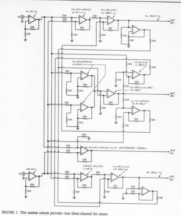
Fig. 1
SPECS:
Input Z *. > 100k-ohm
Output Z: < 2k
Power supply requirements:
Frequency response (not limited by circuit design): > 100kHz
Distortion*:
0.05% THD
*Depends on op amp used.
------------------
ABOUT THE AUTHOR
Mr. William R. Hoffman has held various engineering positions, with a number of different manufacturing companies and other businesses during his professional career. In addition, he is teaching college level courses in both electrical and electronics technology and engineering. He is a freelance writer, writing on many subjects including: transducer design, electronics circuits, and architectural acoustics. His credits appear in Speaker Builder, Modem Electronics, and the Journal of the Audio Engineering Society as well as Audio Amateur. Mr. Hoffman is a member of the AES, and the Acoustical Society of America.
----------------
Also see: