Depts and Regular columns
- Intro
- Editorial
- RECORDINGS In My Opinion by Don Spangler
- AUDIO AIDS By J.J. Curcio, Benjamin Poehland and Willard L. Ramsay
- KIT REPORTS The Hafler Tuner DH-330 By Walt Jung; Merrill Mods for the AR Turntable By David W. Davenport; The IR 2200 Stereo Image Expander, By James T. Frane
- CLASSIC CIRCUITRY -- Grommes Model 207A Preamp
- SHOWCASE The SP450 Tube Preamp, By Jerry Saunders
- JUST LOOKING
- LETTERS (with CORRECTIONS)
Intro
Gary Galo starts this first 1986 issue with an idea that's been on his back burner for awhile but comes to a full boil on (here). His design not only lowers line voltage distortion in turntable motors, but also controls speed precisely, a boon for those who need to adjust off-speed disks or who have perfect pitch problems.
Are you toying with the idea of buying stereo TV? Roy Trumbull of San Francisco's KRON-TV helps us decide whether stereo TV is for everyone, where technology is and what it lacks, on (here).
Contributing Editor Erno Borbely completes his preamplifier (spelled with two “i's,” unlike our 4/85 cover) with Part II of his article, which many of you have been anxiously awaiting. We look forward to your comments and appreciate your enthusiasm.
True three-channel sound for stereo/video systems is an idea William Hoffman has been trying to reproduce simply since hearing Dolby multi-channel systems in large theaters.
James Boyk who is a concert pianist and teaches physics favors us with a guest editorial on (below), which offers some fresh perspectives on microphone placement and other issues at the technology/aesthetics interface.
Next time: We begin a series on fundamentals of vacuum tubes by Bob Mcintyre, author L.B. Dalzell designs and builds a state relay for safe power control, Bern hard Muller offers a precise gain of ten amplifier, Dan Coyle modifies the Hafler DH-100 preamp and Karl Lang constructs a compact 20 watt class A MOSFET power amplifier.
-----------------
We regret the confusion and inconvenience caused sub scribers by errors and omissions which occurred in our circulation department during June to December 1985. The department is now operating smoothly again. If you are still experiencing difficulty with your orders, please document your problem and payments fully and we will rectify it promptly.
-The Publisher
--------------
EDITORIAL
On Both Sides of the Microphone
As a pianist I'm normally in front of the microphone; but as producer of my own concert records, I work on the other side, too. Often I'm asked how I approach this double role; and what follows is an attempt to sketch an answer integrating the views of both sides.
To me, as to many people, music is most importantly a language of the emotions. I want to record not mere sound but a communication in that language. This implies someone to communicate with: an audience. And it implies a reciprocal exchange which is specific to the occasion.
We can say that performer and audience are in a communicative loop, a feedback loop. The audience hears the music; the artist hears his sound in the hall and the audience's response. If the room is reverberant, intuitively the artist plays slower for clarity. If it is “dry, ” a quicker tempo maintains the flow. A bright or dull hall calls for the player to make appropriate changes of tonal balance. If listeners fidget-the artist knows by the quality of their breathing and all the little noises restless people make-their attention may be recaptured by shaping melodic lines more lucidly or making the dynamics more extreme: louds louder and softs softer. If the audience is deeply responsive, the performer may be inspired to reach interpretive heights. In these moments, the artist transcends more than just notes. He forgets about the music itself, and experiences only the emotion changing and flowing through him.
Such an exalted state is rare. But for me at least, the chances of even an ordinarily good performance, without an audience, are nil. So the producer's first responsibility, I believe, is to create a favorable occasion by bringing together an audience ready to listen and a per former ready to play. Then the goal should be simply to record accurately the succeeding acoustic event.
The recording must be accurate because any inaccuracies will occur outside the performance feedback loop, so the artist cannot correct for them. If electronic reverberation is added, for example, then the tempo will make no sense; for we have seen how the artist adjusts tempo to the hall's reverberation. If the tonal balance is changed by “equalization,” then the artist's ear for sonority will seem defective. If “compression” is used to make the louds softer and the softs louder, the recording is technically easier to make; but then one of the prime carriers of musical emotion is thrown away.
All such changes interfere with the delicate relations of sound and sense; so the first imperative is: Leave it Alone! And leave the continuity alone, too. Every time a wrong note is corrected, the flow of emotion is at risk.
Since most recordings have dozens of splices, it's no wonder that the note-perfect playing rarely adds up to convincing performance.
After “leaving it alone, ” and before attempting to satisfy what we might call “esthetic man ” in the listener, we must satisfy “evolutionary man, ” who as both predator and prey wants to know where a noise 1s coming from, instinctively turning his head toward any sound of interest. But virtually no modem recordings allow you to locate the instruments this way; nor do you get any sense that they even had a stable location in the recording hall. These problems come from the use of spaced micro phones; something like having one ear at the piano and the other in the balcony.
The solution has been known for over 50 years, since stereo was invented by Alan Blumlein. Use just two microphones in the same spot, one immediately above the other and aimed in a different direction. This gives superb stereo, such as most people have never heard. And as a bonus, it avoids yet another weakness of spaced mikes, namely the smearing of instrumental attacks, the noises which begin all musical notes. Crucial to identifying each instrument, these are altered for expressive purposes by the artist. When microphones are spaced, the attacks arrive at the two (or more) mikes at different times. To the listener's ear, and depending on the exact distance between the microphones, each attack will be either ac-tually multiplied or at least broaden ed in duration. Even the lesser effect is enough to make a piano sound like a giant guitar; and no matter what the instrument, this approach homogenizes the performer's expressive variety. Coincident mikes don't have this problem for the simple reason that there is no time delay between them.
Attacks will be caught better yet by “ribbon” type microphones. Compared to the almost universal “condenser, ” these have lighter diaphragms more responsive to quick changes and fine detail in the sound.
They also preserve tone quality more independently of the angle from which the sound comes. This matters because the music arrives at the microphones from a variety of positions, and the mikes must treat these evenhandedly to avoid a peculiar sort of equalization dependent on location. Whether because of these virtues or others, ribbons capture such things as the harmonic development of a sustained piano tone, or a certain “adamant ” quality in piano attack I've heard.
So far I have described three major differences between most recordings and my own approach: recording with audience, miking with a coincident pair, and using ribbons. If I were magically given three wishes for improving the world's recordings, I would wish for everyone to adopt these practices. or so I would have said a few years ago. But now that digital recording is so widespread, I would ask for a fourth wish.
The producer who has followed the path I've indicated so far might well feel sanguine about his recording. He has the performance going well, he's picking it up beautifully with coincident ribbons, and he can retreat finally to his own den, the control room, where the sound heard through the monitor speakers is truly remarkable. At last, he has a high quality electrical signal to be recorded on tape, cut on a master lacquer, and pressed in vinyl. From here on, it should be a straightforward process.
He now finds to his dismay that the artist can give a good performance much more reliably than the producer can make a good recording of it. Tapes, lacquer discs, vinyl pressings-all have their effects on the sound and thus on the musical emotion. One vinyl makes a finished record which sounds very close to the master tape, while another, made on the same press, has muddy attacks, compressed dynamics, and altered tonal balance. Use the better of the two vinyls but change the press itself, and again you have an unacceptable record. Musical dynamics, attacks, articulation-all are vulnerable. Tem po survives best; but if reverberation is lost from the signal anywhere in the long recording chain, then the tempo, though factually correct, will be nonsense just as much as when reverberation is intentionally added.
In this morass of equipment and processes, my own choices of analog recording, tube electronics, ribbon mikes, and all the rest, are dictated not by ideology nor a desire to be different, but by my perception of what best serves the music. Getting on the digital bandwagon, producing com pact discs from digital master tapes, would be cheaper and quicker than the process I use. But to me digital sound is anti-musical; and “Thou shalt not follow a multitude to do evil.” Bertrand Russell said of a friend that he would not follow a multitude even to do good. I trust that that does not apply to me or the other producers around the world who share at least some of my views. In this particular case, the multitude, I believe, would be better off following us.
For information on Mr. Boyk's recordings see below.
-------------
James Boyk's Albums & Where to Find Them
The Performance Recordings series now includes five records, all recorded with audience, using coincident crossed-figure-eight miking, and direct to the two-channel master tape from which the master disc was cut with no compression, no limiting, no bass blend, and no equalization (apart from RIAA). Album PR-2 used a condenser microphone; the others use a variety of ribbons. Albums PR-3, PR-4 and PR-5 are All-Tube Analog recordings.
PR-5: BEETHOVEN “Pathetique ” Sonata, Opus 13 BEETHOVEN Bagatelles, Opus 33
DEBUSSY Reflections in the Water
STRAVINSKY Sonata (1924)
SCHOENBERG Six Little Piano Pieces, Opus 19 RAVEL Sonatina
PROKOFIEV Sixth Piano Sonata
SCHUMANN Scenes from childhood
CHOPIN Fantasy in F Minor, Opus 49
SCARLATTI Three Sonatas
BEETHOVEN Sonata No. 32 in C Minor, Opus 111
Many stores in the USA and the UK stock these Performance Recordings albums. If they are not in stock, the buyer will be happy to order them from the distributor. You can obtain them direct. In the USA and Canada, each album is $15.98 postpaid from Harmonia Mundi, USA, 3364 So. Robertson Blvd., Los Angeles, CA 90034. In the UK, each is 19.50 postpaid from Sheffield Lab ( Europe) Ltd., Suite 1, 30 Upper High St. Thame, Oxon OX9 3EX, England.
From Other Countries, write direct to Performance Recordings, 2135 Holmby Ave., Los Angeles, CA 90025-5915, USA.
------------------
ADs:
BRIGAR ELECTRONICS for INDUSTRY
Warehouse and Offices 7-9 Alice Street, Binghamton, N.Y. 13904
Phone: (607)-723-3111
Wire and Cable Sale
WIRE BELOW MFG COST Alpha* Belden* Brand Rex* C&M* Phalo* and More
*PVC Hook-UP Wire
*Multi Conductor Cable
*Electrical
*Coax Cable
*Teflon
*Tefzel
*Kynar
*Flat Ribbon Cable
-----------------
CRAMOLIN How many times have you “fixed ” equipment by rocking a printed circuit card in its edge connector? Have you ever taken an eraser to gold plating? These methods don't get at the heart of the oxide contamination problem.
CRAMOLIN does. CRAMOLIN is a product carefully formulated to insure good and lasting electrical contact in electronic equipment of all types.
CRAMOLIN pays for itself in reduced down time. It takes very little CRAMOLIN to protect every wiping contact even in a large system. If you've ever spent hours tracking down an open ground in a connector CRAMOLIN belongs in your toolbox. The kit comes with instructions for use, two gram containers (red for old contacts and blue for new contacts), applicator brush and lint free cloth. Each $18.00 Postpaid USA. Canada add $1.50 postage and $.50 for each additional item. Foreign add
$3.00 and $1.00 for each additional item. Please remit in US funds.
Discount: $25-$75 =10 %
$75 and up =15 %
------------
Audio Amateur Loudspeaker Projects
Twenty-five articles on Contents Loudspeaker The LC/H Q Mark 1, Part 1 by Peter J. Baxandall construction projects The LC/H Q Mark I, Part 2 by Peter J. Baxandall An Electrostatic Speaker System, Part 1 by David P. Hermeyer appearing in An Electrostatic Speaker System, Part 2 by David P. Hermeyer Audio Amateur Reduce Speaker Distortion by Tuning a Pipe by Nelson Pass: A Transmission Line Speaker by J. Theodore Jastak Magazine How to Photograph Sound by Edward H. Parker 1970-1979 An Electrostatic Speaker Amplifier, Mark II, by David P. Hermeyer A Jolly Transmission Line Giant by J. Theodore Jastak A High-Efficiency Mid- and High-Range Horn by James Nicholson Back to the Wall by Alan Watling A Proven Transmission Line Loudspeaker by B. J. Webb Speaker Evaluation: Ear or Machine? Part 1 by Roger H. Russell Speaker Evaluation: Ear or Machine? Part 2 by Roger H. Russell In Defense of the Ear by James S. Upton The Compact Tower by Lynn B. Neal The Sanders Electrostatic Speaker, Part 1 by Roger R. Sanders The Sanders Electrostatic Speaker, Part 2 by Roger R. Sanders Design and Build a High Efficiency Speaker System by Michael Lampton, Robert Bouyer and William Bouyer The Folded and Stapled Bass Horn by Neil Davis An Amateur's Version of the Heil Air Motion Transformer by Neil Davis A High Efficiency Electrostatic Loudspeaker System, Part 1 by David P. Hermeyer A High Efficiency Electrostatic Loudspeaker System, Part 2: by David P. Hermeyer The Big Bass Box by David Ruether The Little Big Horn by C. R. B. Lister
RECORDINGS
IN MY OPINION
by Don Spangler
I usually START my reviews with some notes on improvements I have made in my playback system. This is what “audiophilism ” is all about. During the past few months, I have modified my Jung preamp with a LIPS power supply module from Musical Concepts (1060 Fifth Plaza, Florissant, MO 63031). This is essentially the same as the Sulzer supply. My previous supply was a surplus potted module manufactured by Burr Brown. The result of the modification is better-defined sound. The bass is more detailed and less tubby, with more fundamental, and the sound is generally more relaxed and less compressed.
As I reported in my last column (TAA 5/84, p. 50), Monster Cable was kind enough to send me an Alpha II cartridge to review. After breaking in the Alpha II for many hours, I assembled a panel of the best ears I know, and we com pared the Alpha II to the Alpha I. Both are excellent cartridges, the best we have heard. The Alpha II has a very detailed sound, but the Alpha I seems more musical and has a somewhat broader sound stage. Both do an excellent job with massed strings, with the Alpha I slightly favored, probably because it is a bit duller. With both units, the sound stage is incredible, and imaging is excellent.
Komnet Har Sun Vila. Storkyrkans Choir.
Gustaf Sjokvist, director. Arrangements by Bengt Berg. Proprius 7853 ! This is another outstanding record from Proprius of Sweden and the recording genius of Bertil Alving. Alving has a remarkable technique of recording the great space and vaulted ceilings of a large cathedral, conveying a rich conscious ness of ambient space. In these religious songs, the choir is accompanied by an organ, guitar, flute and bass. The arrangements are easy and unsophisticated, and the blend makes for pleasant listening. Bengt Berg, the arranger, is also the organist.
If I knew Swedish or had a friend who could translate, I would tell you more about this recording. I wish Audio Source, the importer, would encourage Proprius to use an English album cover.
I am familiar with only two of the songs:
I know the title song as a Christmas carol, and I recognize “Nar videlar det brod ” ('Let Us Break Bread Together on Our Knees ”). Aside from the translation problem, however, this record is pure pleasure.
Sir John Alot Of. John Renbourn, guitar.
Lost Lake Arts, Division of Windham Hill LL-0084.2 This record was originally released in 1968 by Transatlantic Records as Sir, John Alot of Merrie Englandes. The new release is excellent. John Renbourn is backed up at times by finger cymbals, African drums, glockenspiel, flute, recorder and bass viol. Side 1 contains music in the tradition of the often melancholy 'Merrie England’ ballads, while side 2 offers jazz, mostly blues with its pulled strings. The contrast of the two makes the record very interesting and enjoyable.
Apparently, this record was multi miked in separate rooms. The instruments on each cut are in different positions and are closely miked. Normally, this bothers me, but it seems to work quite well here.
Walton: Facade. Strauss: Till Eulenspigel. Scriabin: Waltz in a Flat. Nielsen: Serenatain Vano. Chicago Pro Musica.
Reference Recording RR-16.3 The chamber music ensemble known as Chicago Pro Musica is composed of principal players from the Chicago Sym phony Orchestra. The ensemble was re corded in Chicago's Medinah Temple, whose fabled acoustics are evident in many outstanding recordings of the Chicago Symphony Orchestra. The scoring is also first class, demonstrating many combinations of instruments.
The recording engineer, Professor Keith Johnson, has given audiophiles a landmark recording. Once again, his miking technique provides a good sense of space and superb imaging, with never a doubt as to where the instruments are located in depth or width. The percussion is behind the rest of the orchestra, where it belongs. My favorite cut is “Till Eulenspigel ” because the arrangement depicts the merry pranks well. The violin is true, with just the right amount of gut. The recorded sound of the bass violin is the best I have heard, as it pro vides a solid, realistic, gruff sound. The clarinet, which on other recordings is often mutilated to an unintelligible sound, comes through clearly here.
Overall, this record rates a 10 on a scale of 1 to 10.
Rimsky-Korsakov. Scheherazade.
Chicago Symphony Orchestra. Fritz Reiner, conductor. RCA ARP1-4427.2 This RCA release on the Red Seal.5 Series has been remastered at half speed from a legendary 1960 recording in Orchestra Hall. The master was plated by Europadisk and pressed by Teldec.
This 25-year-old recording is a gem.
First, there can be no doubt about the quality of the Chicago Symphony sound of this period. Fritz Reiner was at his best, and his interpretation is superb.
Further, the recording engineer produced an outstanding tape that has now been remastered with more advanced techniques. This record will bring you to Symphony Hall with all the grandeur of a top-notch orchestra and one of the better conductors of all time. The strings are real, the sound stage is commend able, the dynamic range is extended, and the sound is full.
Mozart: Serenade #11 in E-flat Major for Wind Octet. Grieg: Four Lyric Pieces Transcribed for Wind Octet. The Chicago Symphony Winds. Sheffield Direct Disk LAB22.4 Doug Sax and Lincoln Mayorga have teamed up to produce this direct-disk recording of an ensemble of eight wood wind artists from the Chicago Sym phony. Sax used a single-point stereo microphone with the usual Sheffield tube electronics. The clarity is remark able, and the recording is relaxed and natural. The Grieg arrangement is the product of the first bassoonist, Willard Elliot, who did the arrangement. This is a “must ” recording for all woodwind lovers.
Respighi. Church Windows. Pacific Symphony. Keith Clark, conductor.
Reference Recording RR-15.3 Reference Recordings has succeeded in recording this old chestnut in all its splendor, putting the enormous dynamic range of the score on a phonograph record. With this range, who needs digital? When the giant tam-tam is hit, the sound will knock you out of your seat. Although the very soft passages tax a tape recorder's ability and the transfer to vinyl in terms of the bottom of the dynamic range, Reference meets this challenge admirably. In addition, the high levels show no sign of strain.
This is predominantly a distantly miked recording, but the tam-tam was more closely miked. The recording, which was made in a Santa Ana, California, high school, has a good sense of space. Unfortunately, the organ passage seems not to blend acoustically with the rest of the recording, as it is more spacious. To my ear, it seems that the room's acoustics worked against the recording to produce a slightly muddled sound. Maybe closer miking would have helped. The instruments are just not as detailed in character and sound stage as I would prefer. There is ample depth perception, however, and overall, this is still a dynamite recording. It will be very difficult for many playback systems to reproduce it without strain.
I purchased a Magnavox (Philips) 2040 compact disk (CD) player several months ago as an experiment. At $260.00 how could I go wrong. When it arrived I played two disks I had bought and was not overly dissatisfied with what I heard, but it was nothing great.
Just so-so.
I decided to modify the analog section of the 2040. I replaced the interstage electrolytics with polycarbonate film caps, which improved the sound. Next I changed the resistors to Corning and the dual opamps to TL072's (both available from Old Colony).
My experience indicated the bi-FET TLO72s sounded better than any bi-polar op amp. I followed these changes with a separate + 15V power supply (Old Colony) from the analog section and better interconnected wire (Apature). Now the sound was much better on some disks.
I have been negative about digital sound in the past, but my experiment indicated to me that given a well record ed disk and a player, such as my modified Magnavox, the sound can be quite respectable. Compact disk sound tends to be harsh, but many phono records are harsh too. It does not lack stereo image or depth perception, and the dynamic range is spectacular. So, as an about face, I am reviewing some of the outstanding CDs I have run across.
The compact disk and phono record reviews that follow were mostly found at the summer Consumer Electronics Show in Chicago.
Beethoven, Wellington's Victory. Liszt:
The Battle of the Huns and Hungarian March of the Assault. Cincinnati Symphony Orchestra, Eric Kunzel Conductor. Telarc CD, CD-80079.5
“ Wellington's Victory” is a show piece with curiosity. The cannons and muskets will show off your system.
However, it is the ' Battle of the Huns' “ I want to rave about. Mind you this is a CD, but this take is one of the best recordings I have heard. The massed strings and horns are life-like, the horns are not overly raspy and the strings re main silky and smooth, even at high volume.
The CD has great depth and a well placed sound stage. The dynamic range of this great symphonic poem by Liszt is awesome. If compact disks could be worn out I would have destroyed this one. Telarc seems to be doing a respect able job producing their disks. They have some of the best.
Windham Hill Records Sampler '84.
Windham Hill WD-1035 (CD).5 “Sampler '84 ” is great Windham Hill
jazz from their many artists like Hedges, Isham, Winston and Shadowfix. This disk is wonderful listening. Some of the jazz is pensive, like “Thanksgiving ” by George Winston, and some is dynamic like the cut with Mark Isham. All cuts are complete.
After a tense day at work I find this disk a great way to relax. It is not too gentle-just right.
Test Record 1, Depth of Image, Opus 3 CD7900, CD.5 This sampler compact disk is every bit as good as the well-known analog record by the same name. However, dynamic range is much improved with the CD format. I suggest that you purchase both analog and digital versions, and com pare. I believe you will choose the com pact disk version.
For those not familiar with Opus 3, they are a Swedish company dedicated to the best possible recordings of folk, jazz and classical music. All of the instruments are acoustical. No electron ics.
In this disk Opus 3 demonstrate their ability to capture depth in a recording.
I assure you that few recordings have greater depth. Each cut has an excellent account of the notes you should be able to hear. The disk has a very natural and accurate sound. I think you will enjoy the placement of instruments.
Stravinsky. L'Histoire du Soldat, Rimiky-Korsakov, Capriccio Espagnol.
Chicago Pro Musica. Reference Recordings RR-17.6 Again Keith Johnson has returned to the wonderful acoustics of Medinah Temple, and again, recorded the Chicago Pro Musica ensemble. It has great detail and a feeling of space. The ensemble is alive before you in a hall of first rate acoustics. Every instrument is without any noticeable color. Even the dynamics are admirable. A very rare record.
I must confess that “L'Histoire du Soldat ” (The Soldier's Tale) is not a favorite of mine. The acrid dissonances are often more than I want to hear.
However, it contains some wonderful rhythms-march, waltz, tango, ragtime and chorale. It was composed for a chamber orchestra, so the Chicago Pro Musica is about the right size.
The 'Capriccio Espagnol' is a favorite of many. It is a symphonic suite, a masterpiece of orchestration. Native melodic figures and dances call forth a Spanish setting. The arrangement, for only nine instruments, retains the form of the original score. I found it quite interesting.
James Welch, Discovery. James Welch, organist. Wilson Audio W8419, phono record. ” Few compare with Dave Wilson's ability to capture the sound of an organ in a church setting. Dave has brought us many excellent recordings and this is no exception. The organ is a Schoenstein and the church is St. Mark's Episcopal of Los Olivos, California. The organ was built by a San Francisco firm, with modest specifications. But the sound that Dave captures is full-bodied with a wonderful feeling of the space in the church. When the organ swell shades are closed it has an antiphonal effect.
The music ranges from the 1700s (Bach) to the present (Longhurst). “The Toccata, ” from Widor's fifth symphony, is a favorite of many, this writer included, and is as vigorous as it should be. James Welch, the organist, interprets this widely varying program in a competent manner. Organ buffs need this record.
Stravinsky, Firebird Suite. Debussy, Afternoon of a Faun. Los Angeles Philharmonic Orchestra, Eric Leinsdorf conductor. Sheffield, LAB24. Direct disk. This was the white label Consumer Electronics Show preview record. It has been some time since Sheffield has had a classical white label at CES. Again they have recorded this major orchestra and conductor. It was recorded April 29, 1985 with their single point microphone and vacuum tube topography. The sonics are excellent with the clean clear natural sound for which Sheffield is noted.
The perspective of this recording is noteworthy. It is not from a front row seat, but back maybe ten rows. The important issue is that Doug Sax and James Boyk, engineers, do not lose any detail from this perspective, as is so often the case. The recording has an unusual amount of depth from front or back. It is definitely a recording with which you can close your eyes while listening, and picture the whole breath and width of the symphony orchestra. My only com plaint is rather noisy surfaces, but CDs may have ruined me in this regard.
The “Firebird” on this recording is a suite of music from the ballet by Stravinsky in 1910. This predates the more popular version of 1919. I was not aware of the 1910 version, which the composer arranged in the same year the ballet was first produced.
The dreamy “Afternoon of a Faun ” is well interpreted. This sensuous sym phonic poem is considered by many musicologists as one of the first realizations of “impressionism. ” The tonal colors suggested in this rendition are in tangible and vague, just as the composer intended.
Ric Swanson, Urban Surrender. American Gramophone Records AB-600. An excellent release from the “Fresh Air ” people. This music, written by keyboard/percussion player Ric Swanson, is in an easy going electronic jazz style. The instruments are keyboards, saxophone, guitar, bass, piano and percussion. I don't generally prefer multi miked and mixed recordings, but this one certainly deserves an audience. The interplay of the many sounds and instruments on this platter is both enter taining and pleasing. The music is not intended to be a block-buster, and it isn't. Expect a sound that gratifies and stimulates your senses.
Edward Parmentier, Early Italian Harpsichord Music (1520-1670). Edward Parmentier, Harpsichordist. Wild Boar WLBR 8001. Phono Record. Peter Sutheim of Earthworks is the recording engineer for this analog disk made with a coincident pair of figure eight ribbon microphones with no compression or equalization. If you think a condenser mike is required for good fidelity, listen to this recording.
I have used ribbon microphones for years and they are capable of excellent sound. They tend to have a more “serene ” sound than many condenser mikes, and are an excellent choice for harpsichord music. The figure pattern gives a marvelous ambience to this recording.
The harpsichord is a Jerome Proger copy of an original made in Sicily in 1697 by Grimaldi. The sound is rich with the complex overtone structure typical of an Italian instrument.
The recording is made at a higher than normal sound level for a harpsichord. I suggest you turn down the sound level to better match the voice of a harpsichord. This will also reduce some noticeable tape recorder hiss, and result in a very believable harpsichord sound.
Edward Parmentier, is an active and accomplished recitalist on the University of Michigan faculty.
SOURCES
1. AudioSource, 1185 Chess Drive, Foster City, CA 94404.
2. Local dealer.
3. Reference Recordings, Box 77225X, San Francisco, CA 94107.
4. Sheffield Lab Inc., PO Box 5332, Santa Barbara, CA 93108.
5. Local Dealer
6. Reference Recordings, PO Box 77225X, San Francisco, CA. 94107
7. Wilson Audio, 655 Louise Avenue, Novato, CA 94947
8. Sheffield Lab PO Box 5332, Santa Barbara, CA. 93108
9. American Gramophone, 9130 Norman Bridge Road, Omaha, NE 68152
10. Earworks, 5146 Almaden Drive, Los Angeles, CA. 90042
---------------
Why Your Magazine Doesn't Arrive
If you move and do not send us your new address in advance, AA is sent to your old address. AA is a quarterly and may arrive after the Postal Service's six-month time limit on forwarding instructions has expired. If this happens, the Postal Service sends us a notice saying, in effect, they have forgotten where you now live, along with a bill for 25¢ to pay for this information. Meanwhile, they have trashed your Audio Amateur.
Since we have already paid for your destroyed copy, paid postage to at tempt to deliver it to you and put a holding code in your computer record saying that we have no idea where you are, and further since we routinely act on the assumption that Murphy is overactive within most offices of the Postal Service, we send a first-class letter to your old address to determine whether you have, in fact, moved. We do this because from time to time some clerk mistakenly supposes a subscriber has moved and he or she has not. Then we write a nasty letter to the postmaster suggesting the clerk is a vandal of sorts and how about paying for the magazine? So far, not one has sent any postage or even a repentant letter. Replies usually range from form to frowning to foaming.
So please inform us early when you move. Peel off your label, put it on a post card, write in your new address and send it to us. We cannot afford to send you a duplicate, unfortunately. If your copy becomes a Postal Service casualty, the replacement copy will cost $4.
---------------------------
KIT REPORTS
THE HAFLER DH-330: A HIGH-TECH TUNER
Reviewed by Walt Jung
IT Has ALWAYS BEEN somewhat of a mystery to me that audio hobbyists have given the world of FM stereo short shrift. Rarely is it even discussed at all, with the predominant focus being on amps, pre amps and disk/tape sources. When FM is mentioned, quite often it is in a derogatory sense. Perhaps this is because some people have never explored the potential of FM broadcasting.
FM has a lot to offer audio enthusiasts, not only in program diversity, but also in audio quality. If you are lucky enough to be within range of one or more National Public Radio (NPR) sta tions, that is half the battle (the source).
I have been a regular FM listener for years and have been experimenting with FM circuitry since the days of the Heath FM-3. Until recently, my FM tuner was a (much-modified) Heath AJ-15, which served quite well.
I was, therefore, intrigued to learn about the Hafler DH-330. It sounded interesting-a frequency-synthesized, crystal-stabilized tuner with an on-board microprocessor for tuning and control.
I wondered whether the microprocessor was a “gimmick ” (storing call letters for display when tuned) or whether it was used to improve reception quality. I finally decided to take the plunge and try my first new tuner in many years.
My son Mark, a veteran kit builder (with two computers and several scratch and kit preamps, as well as power amps behind him), sailed through the kit in a few hours. He found few problems, and the unit worked when he first turned it on. The only snag of any con sequence was a pair of front panel circuit cards that were not snapped apart before shipping, thus preventing their installation. Fortunately, they were pre scored so he rectified this easily.
All in all, the DH-330 assembly process resembles that of other Hafler kits:
you do not have to stuff circuit cards at all. You do the overall mechanical assembly and wire up the already assembled, aligned and tested cards. Hafler does all the critical adjustments, which is no mean feat when you consider that this is a state-of-the-art tuner in terms of performance. This alignment includes not only the radio-frequency (RF) front end, but also the intermediate-frequency (IF) amp/detector and the phase-locked loop (PLL) stereo decoder.
The DH-330 is available in a wired version, but I do not think anyone who has soldered an electronic assembly should have trouble wiring the kit. The list prices are $385 for the kit and $460 for the wired version from the David Hafler Company, 5910 Crescent Blvd., Pennsauken, NJ 01809.
The Layout A front panel layout of the DH-330 is shown in Fig. 1. As you can see, it has no conventional tuning knob, as tuning is entirely electronic.
The large rectangular window at the left includes the four-digit frequency tuning display (center), a vertical bar type LED signal strength display with log characteristics (left), and two single LEDs for stereo and 50kHz indications (right). The stereo LED's function is obvious, while the 50kHz LED indicates a mistune (in the US). You might use this if you wanted to detune a difficult station slightly to improve reception. In foreign countries that use 50kHz channel spacing, this LED will normally indicate correct tuning.
The five rectangular memory push buttons across the top middle of the panel are used to recall five preset channels for immediate-access tuning. You can select a given channel by pressing the appropriate button (1-5) or scan all five in sequence with the scan button (right of the presets). The store button stores a station on one of the preset but tons. You just tune the channel, then press “store ” and preset number.
Since all DH-330 tuning is via frequency synthesis and is referenced to a master 4MHz crystal, “old-fashioned ” mistuning cannot occur. Should you wish to tune in another (non-preset) station, you (momentarily) press the auto tuning button on the lower tuning row.
This will cause the tuner to scan up the dial, stopping on each listenable channel. The tuning process is muted between stations, and the muting effectively quiets tuning transients.
After tuning in a station during a scan, the DH-330 will disable the muting and wait for five seconds on each channel.
Should you wish to listen to a certain station, you simply press the halt but ton. This also locks the station in memory. The station tuned in when you turn off the unit will reappear when you turn it back on. If you decide to continue the scan process, another press of the auto button will restart it immediately.
The muting sensitivity is adjustable (muting is controllable from the two left-most push buttons on the right) and can be set to receive only the stronger stations or all tunable stations.
As you might imagine, manual tuning of the entire dial from 88.1 to 107.9MHz is necessarily slow, particularly if you have the sensitivity on high, have an outside antenna and are blessed with a lot of stations. You can speed it up by holding down the auto button, which causes the DH-330 to shift gears and speed up the tuning. The tuner will stop on the next available station only after you release the button.
While this works about as well as I sup pose it can, it is still not as direct as going right to a given frequency.
The DH-330 has no direct-access tuning method except for the five preset: mentioned above. Many of you might consider this too few, and I have occasionally wanted more. Given the relatively low front panel height, however, a keyboard for direct-access tuning would probably be stylistically incompatible, and it would have clearly labeled the tuner a “techno-product ” (some thing Hafler might not have wanted). In any event, the scan tuning does work quite smoothly, and it is reversible.
Overscan beyond 108MHz wraps continuously around to below 88MHz, and the unit will even tune channel 6 TV audio for you.
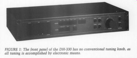
Fig. 1
The remaining push buttons on the right of the quad array select 'mute off'
KIT REPORTS (still active while tuning, however), “auto-stereo ” and “auto-filter. ” The last is quite novel and allows some compensation for the 23dB noise disadvantage of stereo versus mono. This will be most a t when receiving a weak and noisy stereo signal. In such cases, the DH-330 brings a special circuit, the noise detector, into play. It applies a control signal to a high-frequency noise reduction circuit, reducing both the noise and the high-frequency separation of a noisy signal. In practice, you will lose some high-end stereo effect with this filter active on a weak signal, but you will also lose a lot of the noise. This can be a real blessing and make receiving a distant station in stereo tolerable.
The circuit is smart enough to vary noise reduction automatically and correctly, so you may leave it on continuously without loss on clean signals.
The DH-330 has a large, smoothly operating output level control at the right.
It controls the front panel stereo head phone output and the conventional rear panel RCA-type phono connectors. The power switch at the extreme right completes the control complement.
Block Diagram
The circuitry represented in the DH-330 block diagram (Fig. 2) is contained on two large circuit boards and several smaller boards.
The FM signal entering the DH-330 is connected through a 30 0-ohm input or a 75 ohm coaxial jack and is passed internally to the varactor-tuned front-end sub-assembly. This stage accomplishes the RF amplification and down conversion, and it produces output at a standard 10.7MHz IF. A sample of the local oscillator is also fed to the PLL synthesizer.
Following the front end, two discrete transistor stages of IF gain with four ceramic bandpass filters precede the IF limiter/detector stage. This stage is accomplished with a single Hitachi HA11225 IC. The HA11225 is apparently a close cousin of the standard CA3089 IC and features very high performance specs. It is capable of an 84dB signal-to noise (S/N) ratio and a typical detector distortion of 0.03 percent. It also pro vides a logarithmic signal strength out put, used in the DH-330 to drive the LED bar indicator and the front-end automatic gain control (AGC). The detector is a double-tuned quadrature type, with adjustable damping for lowest distortion.
Following the IF detector, the wide band audio-frequency (AF) signal is split, with one path to the IF noise detector and the other to a PLL multiplex decoder IC made up of a Hitachi HA12016 IC.
The noise detector monitors the IF noise level at an ultrasonic frequency. When this noise is high, it enables HF noise reduction.
The multiplex decoder IC is similar to standard MC1310 and LM 1800 series de vices, but it is not identical in pin-out or function. Like the HA11225 vis-a-vis its related devices, the HA12016 features improved performance, with a typical S/N of 88dB quoted and a low distortion of 0.01 percent, plus the utility of low impedance output buffers. A pair of LC low-pass filters, which virtually eliminate all spurious outputs, follow the decoder stage. The stereo audio signal is then buffered again by a dual 741 op amp, and after passing through the muting relay, it is fed to the outside world.
The power supplies for the DH-330 are derived from a single back panel transformer and produce regulated out puts of +/- 12V, +27V and +5V.
Construction
The DH-330 is constructed with standard commercial-grade components and manufacturing techniques. The circuit cards are epoxy glass laminate with double-sided traces and plated-through holes. Although components are easily accessible, the manual recommends
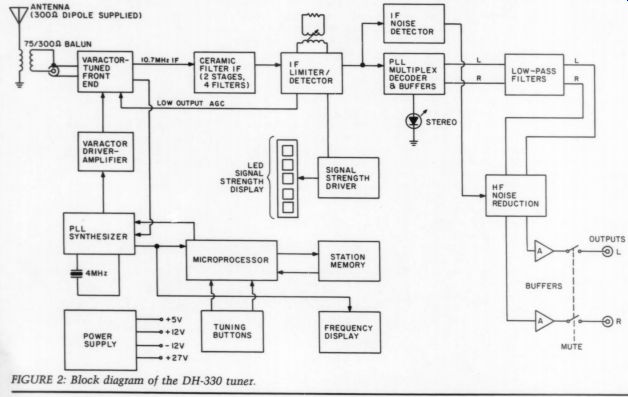
FIGURE 2: Block diagram of the DH-330 tuner.
that you do not service the unit yourself, particularly when alignment adjustments are required. Kit units have a one year warranty, while factory-built units have a three-year warranty.
In some instances, the types of components used suggest that cost was the primary selection criterion. For example, the FM IF, detector and audio sections use many low-voltage electrolytic capacitors and carbon film resistors. The output buffer amp is a 1458 (dual 741) op amp, which has long since been surpassed in performance by many FET units (e.g., the TL072 and the LF353) at little or no cost penalty. (I have suggested to Hafler that they use a plug-in, pin-for-pin dual op amp from a recently introduced high-performance FET family as a possible replacement for the 1458.) The +12V power supplies are regulated by LM317 (positive) and 79L12 (negative) IC regulators. The 79L12 has a moderately low output impedance and is lightly loaded by the DH-330's circuits. I would prefer regulators with lower overall broadband impedance characteristics and perhaps better bypassing at the loads, as most of the circuitry supplied is at the extreme end of the tuner.
These changes might have little effect on overall measured performance, and I do not mean to suggest that the DH-330 fails to meet any spec set down for it. Rather, my suggestions reflect my own approach to similar circuitry.
Performance
Evaluation of a high-quality FM tuner in today's environment of many stations, strong as well as weak and separated by a minimum of 200kHz, requires some thought. Many fine tuners and receivers have evolved as FM has grown, so I will focus on the characteristics of what I would call the “best ” units as opposed to just the “better ” ones.
Raw sensitivity alone is no longer a key indicator of quality. A good tuner must be sensitive, but it must also be free of front-end overload and be able to separate weak signals from strong ones, even when 200kHz apart. Under such conditions, it should be able to deliver a clean, listenable stereo signal. The DH-330 can do this. In fact, I have never seen a hint of overload, even with my outside directional antenna (in a suburban Baltimore location). For instance, it can separate the superbly programmed WITF at 89.5MHz 60 miles to the north from a strong local station at 89.7MHz (WCVT). I do have a directional antenna, but I have seen tuners that would not even detect the presence of the weaker signal in such a case, let alone make it listenable in stereo. My tuner also receives stations that are more equal in terms of signal strength when they are 200kHz apart. For example, it receives WHEFC at 91.1MHz clearly, with WETA to the south at 90.9MHz.
----------------
Specifications
Usable Sensitivity:
50dB Quieting Sensitivity:
Total Harmonic Distortion:
11.3dBf mono, 17.2dBf; stereo, 37.2dBf @ 1kHz, 100 % modulation-mono, 0.1 %; stereo, 0.18 % Capture Ratio:
Alternate Channel Selectivity:
Stereo Separation:
Signal-to-Noise Ratio:
Dimensions:
Net Weight:
Shipping Weight:
1.5dB 60dB 1kHz, 45dB; 10kHz, 35dB mono, 72dB; stereo, 68dB 17 ” W by 3 ”H by 8 1/4 ”D
9 lbs.
11.5 lbs.
-----------------
Alas, there are situations where even a super tuner cannot bail out a desired top-rate signal due to oversights in channel assignments. The FCC's spacing for channels co-occupied does not accurate ly follow the capabilities of modern super tuners. For instance, Philadelphia (100 miles to the north) and Washington (60 miles to the south) have several co channels. I am not close to either, so my reception of these co-channels is mediocre to fair, even with my directional antenna directly on the one I want to hear (the other falls to the back). For example, WETA has sufficient signal at my location, but co-channel WUHY in Philly is always lurking in the back ground. As a result, stereo from WETA is usually accompanied by ample swish and gurgling. This is frustrating, but it is no fault of the tuner.
With an unfettered and clean signal, the sound from the DH-330 can be a real reward. If you are near a metropolitan area with one or more NPR stations that pay attention to the quality of their own signal, you can be so rewarded. In the Baltimore area, we have WBJC, the radio station of the Community College of Baltimore, at 91.5MHz and 50kW.
WBJC has been on the air for many years, starting as a 250-watter at 88.1MHz from a 100-foot tower. Things have improved since then, and Frank Zeiler, WBJC's chief engineer, recently described a host of signal path and pro gram improvements to me. Among them are the use of minimal on-air signal processing, with virtually a straight-line path to the remote transmitter through the present studio transmitter link (STL). The bottom line is that WBJC's signal produces clean sound with a wide dynamic range.
The phono preamp used at WBJC is a nice unit from Straight Wire Audio (SWA), which just happens to have part of its roots in an earlier TAA preamp mod and AES RIAA talk (by yours truly).
Bill Sacks of SWA also believes in the minimal-processing school of thought (in case you missed the name!) and uses high-quality parts. WBJC is involved with live digital recordings of the Baltimore Symphony, using a Sony PCM-1 and SL0420 Beta-format VCR. Interested readers can contact Frank Zeiler at (301) 396-0404 or Bill Sacks at (703) 522-7780.
I certainly recognize that quality FM broadcast sound is not unique to my locale and that there are many more innovative operations. This comes not only from a listener's perspective, but also from talking with many NPR CEs at conferences over the years. FM broad casting is not composed entirely of signals with a 10dB total dynamic range, breathing AGC and clipped, squashed audio sources. A good tuner can be an avenue to much worthwhile listening, given the proper programming and engineering attention.
Conclusions
I recommend the DH-330 tuner to any one looking for more than just another imported technological whiz-bang from the discount store. I cannot fault it in terms of pulling in stations under realistic reception conditions. The only possible caveat is that it has limited direct tuning access, so think about how much that factor means to you before buying.
I have heard some gripes that the DH 330 does not sound as “good ” as other tuners. I cannot tell you how the DH 330 will sound on your system, since we are still stuck in the stone age in terms of communicating information on this vital issue. To me, tuners do not sound alike, any more than the radio stations do. The point is, either the tuner or the station can make for dismal sound, and they both must be right for good sound.
I do not think anyone will be totally disenchanted with the DH-330's sound quality (from a good source, that is). If you think the sound could be better, you can modify the unit. (The complete schematic and parts list are available.) Do not take this as a put-down of the unit; it is long on value in many ways.
You can pay less for a tuner, even one already assembled, but it would probably not perform as well, and you might not get as much satisfaction as with one you build yourself. I hope audio amateurs will value the fact that the DH-330 is the only tuner still available as a kit.
In sum, the DH-330 is a high-performance tuner that can access a rich array of new sounds. I hope you will discover FM and enjoy it as much as I do!
David Hafler replies:
We appreciate Walt Jung's review of the Hafler DH-330 FM tuner. We do question his mild criticism of the criteria he assumed governed our selection of components. We produce commercial products, and we must compete with others.
Price is one of the competitive weapons.
Our philosophy is to make the product excellent in sonic quality and reliability. If a different component would pro duce better sound, we would use it. But we do not use premium-priced components in positions where they perhaps offer psychic satisfaction but do not improve the listening quality of our unit.
We do not think the type of design that Mr. Jung prefers for himself would necessarily make a better-sounding tuner. We do know that it would be more costly for our customers. As Mr. Jung correctly points out, however, customers who agree with his component preferences and are willing to pay the price can modify our units to their own satisfaction.
However, as a result of Walt's re marks, we are now bypassing all the capacitors in the tuner's audio path.
Referring to the power supply, we have followed the regulator manufacturer's recommendations regarding regulator bypassing. In our opinion, bypassing at the loads is adequate, and additional bypassing does not enhance performance.
We would like to mention that our DH-330 is one of the few tuners made in the United States and that it was designed by our own personnel. We are rather proud that we can successfully compete with “off-shore ” products.
Jung replies to Hafler:
I find Mr. Hafler's response an oddity, in view of the company's past position(s) on the influence of components on sound quality. One need only consult one of their brochures, for such products as the DH-160 equalizer, or the DH-100 preamp. Both tout the use of higher quality film capacitors; the DH-160 literature even goes so far as referring to listening tests and differential measurements which support the use of the higher quality parts.
A sample quote:
“Correlation has been observed between such differential measurements and listening tests, particularly in evaluating the audibility of capacitor dielectric materials. This has led directly to the selection of specialty types of considerably higher cost whenever the results so dictated. ” I don't know whether Hafler is saying above that FM tuners such as the DH-330 simply do not need any better capacitors, or that there has been a re cent reversal of the company's position in this regard. In any event, the bottom line seems confusing. For the information of the readers, a capacitor differential test technique that anyone can use to evaluate capacitors, and see for themselves, is described in the Curl Jung article in TAA 4/85, p. 22.
YOUR MAGIC NUMBER HELPS US ANSWER FASTER
ACKNOWLEDGMENTS
I thank Paul Simpson (the primary author of the DH-330) for help in preparing this article. He provided much technical information and background material and offered many useful comments and insights into the DH-330.
Thanks also to Robert Smith of O xford Audio Consultants ( Box 145, O xford, OH 45056). I built two units, one purchased from O xford Audio and the second a sample from The David Hafler Company.
SOURCES
1. Baar, L.S., “Application of the CA3089E FM-IF Subsystem, ” RCA Application Note ICAN-6257.
2. Gay, M.]., “A Monolithic Phase-Lock Loop Stereo Decoder, ” IEEE Transactions Broadcast and TV Receivers, BTR-17, August 1971.
3. Isbell, T.D. and D.S. Mishler, “LM1800 Phase Locked Loop FM Stereo Demodulator, ” National Semiconductor Application Note AN-81.
4. Kaplan, L.A. and A.L. Limberg, Integrated-Circuit Stereo Decoder Using the CA3090A Q Stereo Multiplex Demodulator,RCA Application Note ICAN-6259.
5. Manufacturers' Data Sheets: Hitachi HA12016, HA11225; RCA CA3089, CA3189;
National Semiconductor LM 1800; Motorola MC1310.
MERRILL MODS FOR THE AR TURNTABLE
Reviewed by David W. Davenport
Twenty YEARS Ago, Ed Villchur (of Acoustic Research) laid the foundation for a technology that is found today is some of the better turntables. The fact that the AR turntable of the early 1960s survived with only minor modifications through the 1970s is a testament to its design. The state of the art continued to evolve, however, and although the basic concepts remained valid, their implementation was easily surpassed. What might have been an adequate tonearm in 1964 was sorely lacking 15 years later.
After bowing out of the turntable market for several years, AR has recently rei-ntroduced the turntable with an optional integrated tonearm as the AR-XE. But what about all those thousands of older AR turntables out there? Can anything be done to save them? Merrill to the Rescue Recognizing the soundness of the basic design, as well as the weaknesses in the original AR turntable, George Merrill has developed a series of modifications that can be applied to the AR-XA or AR XB to transform it into a state-of-the-art turntable. The modifications are avail able from Underground Sound ( 2125 Central Ave., Memphis, TN 38104).
The most important of these modifications is a new subchassis made of acrylic. Merrill claims that the significant difference between the great and the merely good turntables on the market is how their structures affect what he calls “tonearm release energy. ” The best turntables absorb this energy rather than reflecting it back into the tonearm.
Many factors are involved in designing an energy sink (which he considers to be the prime purpose of the sub chassis)-the material, the unit's mass, whether or not it has a mounting board, and the size and shape of the tonearm mounting area. Merrill experimented with many materials before settling on acrylic, which he found to be better than any other for absorbing tonearm vibrations.
The subchassis is available for $93 predrilled for the arm of your choice (you supply the drilling template). You can save $8 by ordering the blank sub chassis shown in Photo 1 and drilling it yourself, but I think $8 is a small price to insure against slip-ups. Since the new subchassis is thicker than the original, the suspension screws must be longer.
Merrill includes new screws, as well as a vial of spindle oil, with each sub chassis.
Underground Sound sells a spring kit ($8) that will allow the suspension to support a variety of platter mats, record weights and heavier tonearms. The kit contains six springs (two sets) and a chart to tell you which set to use de pending on the amount of weight to be supported. Merrill suggests the sub chassis and spring kit as a starting point for modifying an AR turntable.
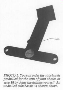
PHOTO 1: You can
order the subchassis predrilled for the arm of your choice or save
$8 by doing the drilling yourself. An undrilled subchassis is shown above.
Although the original platter is good, Underground Sound offers three improvements-balancing ($12), lead coating ($15), or new spindle installation ($25). The lead-coated outer platter rings much less than an uncoated one. The new hardened stainless steel spindle is recommended if the platter is to support more than stock weight.
The new AR-XE turntable has a higher-torque motor than was provided with the older AR-XA or AR-XB.
Underground Sound offers a high-torque replacement motor ($45), which they say will pull a ten-pound platter. The new motor has a stronger magnetic field and is not recommended if you have an unshielded cartridge because the magnetic field will induce hum. (See Andy Catanzaro's letter, “Merrill Mods Make a Difference,” in TAA 3/85, p. 51. -Ed.) In addition to the AR modifications discussed above, Merrill has a complete turntable of their own design, a new acrylic subchassis for the AR-XE and a unique platter mat ($35). I had the opportunity to review a prototype of this new mat, which is a sheet of lead bonded to a styrofoam disk. Merrill believes that lead is superior to any kind of rubber for damping record vibrations because the rubber's top layer of molecules will vibrate under any circumstances. Although the mat has definite sonic benefits (described below), it does have one shortcoming-the tendency to build up a large static charge. I have been told that the production level mat will have a drain wire connected to the lead top, which will correct this problem. It is necessary to use a clamp with this mat, as it is with any hard mat or bare metal platter.
Installing the Mods
Other than disassembly and assembly, installation involves very little work.
The new motor requires that you drill two small holes in the top plate. To pre pare your turntable to accept the new subchassis, you must cut a 2.5-by 3.5-inch L-shaped hole in the top metal plate. Merrill supplies a template to use as a guide for marking the cutout. The boss on the subchassis is large enough to allow a variety of different tonearms requiring holes in different locations.
For aesthetic reasons, I wanted as little of the subchassis showing as possible, so I trimmed the boss to be 2.5 inches square. I later learned that this was a minor mistake because Merrill purpose ly made the boss as large as possible to absorb the tonearm release energy better.
Cutting the hole in the top plate was tedious, but rather straightforward. I drilled a hole in each comer of the cut out and filed them square. Then using a hacksaw blade mounted in a handle similar to a keyhole saw, I cut out the hole. After a little touch-up filing, the job was done. If you prefer to waste your money, you can send your top plate along with $30 to Underground Sound, and they will cut the hole for you.
Reassemble the turntable and mount your new arm. Install the inner and outer platters and adjust the suspension so that the top of the subchassis is approximately even with the top of the base. Support the turntable on several stacks of books so that the base is level and you can reach the adjustment nuts.
Put a record on the platter along with whatever mat and weight you plan to use. Level the platter and check the belt to make sure it is centered on the pulley.
The only real problem I experienced while upgrading the turntable had nothing to do with the Merrill modifications. After I had finished, I discovered that the dust cover would no longer fit on the turntable. The original tonearm was rather low and short by today's standards, so the dust cover hit the counterweight and tip of the headshell on my new arm. | have not decided exactly what to do about it, but I will probably modify the cover in some way.
Merrill said that this was not unusual and that some plastic suppliers will custom make new dust covers for $40 to $80.
Photo 2 shows my AR turntable complete with the Merrill modifications.
While my turntable was disassembled, I decided to give it a facelift. I like wood, so I applied walnut veneer to the top.
The AR-XA's top plate sits on the walnut base about 0.25 inch in from the edge, so I had to fill this area with a 1/16” by 0.25 inch strip of walnut before veneering the entire top of the base.
After the contact cement dried, I applied an oil finish.
Of course, the ultimate objective of any project such as this is quality audio.
I found it hard to start the listening evaluation, though, because I was having too much fun jumping from one favorite record to the next.
Listening Evaluation
After several hours, I settled down and decided to start my evaluation by deter mining the effect of a record clamp on the sound. I tried all combinations of platters and mats, both with and with out a clamp. In each case, the result was the same: without a clamp, the bass lacked definition. When listening to a string bass, I thought it sounded as though the player was wearing cotton gloves. I used a friction-type clamp during all the listening evaluations described here.
I must confess that I entered the test with the feeling that lead-coating the outer platter was only gilding (plumbing?) the lily. Boy, was I wrong! Although the standard platter was very good, the lead-coated platter provided a much smoother, sweeter sound, akin to the sound of tubes. The character of the sound did not change, but it seemed as though a certain distortion (grundge) had been eliminated. The music was clearer, giving the illusion of better overall definition. Using the Merrill mat on the lead-coated platter resulted in no noticeable improvement, but the mat did improve the sound of the original platter to the point that it was equivalent to the bare lead-coated platter.
With a record directly on the metal surface of a platter or mat, I noticed a hardness or brittleness to the sound. The high frequencies had an edge that I wanted to eliminate. After some experimentation, I settled on a very thin car bon fiber mat. The mat, being about as thick and hard as a piece of poster board, did not compromise the advantages of the lead-coated platter. It did, however, eliminate the edge and provided the additional benefit of eliminating a slight smear in the high frequencies that the edge had masked.
I did not perform comparative listening tests between the balanced and un balanced platter or between the new hardened spindle and the original spindle. The lead-coated platter discussed above was balanced, and I used a hardened spindle throughout the testing because the new spindle extends % inch above the platter, which facilitates the use of a clamp.
I really cannot separate the effect of the Merrill modifications from the rest of the system, which includes a Linn Basik Plus LV-X arm with a Shure V15-VMR cartridge, so keep this in mind when reading my comments.
Conclusions
The Merrill-modified AR is an excellent turntable regardless of cost and is certainly the best you can buy for the price of the mods. Although you will not be disappointed with a basic modification limited to the subchassis, I think the platter options are well worth their cost.
Although the original motor might take longer getting the record up to speed and need a little help when you are using a record brush, it will turn even a heavy platter at the correct speed. I think the new motor should be considered only if you are unhappy with the original.
I do not recommend the Merrill mat because it affords no appreciable improvement over the lead-coated platter.
It might, however, be of interest to someone who owns a different brand of turntable and wants to try a hard mat.
If you are not planning on using a heavy mat or record weight, you can probably use the original springs. I do think it is a good idea to have a variety of springs on hand in case you want to add a mat or weight in the future.
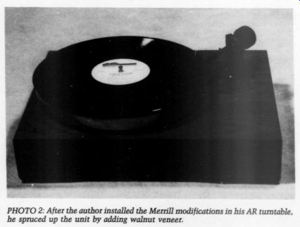
Photo 2.
THE IR2200 STEREO IMAGE EXPANDER
Reviewed by James T. Frane
Like most Audiophiles, I am always experimenting with my stereo in a quest for a more realistic “you are there' reproduction of music. In the past four or five years, I have read a few favorable, and some glowing, reports of the Sound Concepts stereo image expander.
The company's first unit was the Model IR2100, a 1.25-by-3-by-7-inch hand-held unit, which was called an 'image restoration control.’ This unit sold for about $230. It connected to the tape monitor loop of a stereo system by means of a 12-foot cable, enabling the listener to make adjustments from the listening position.
Sound Concepts has more recently marketed the Model IR2200, which is billed as a true “stereo image expander ” and is designed to be shelf mounted.
This unit (Photo 1) is available from Sound Concepts ( PO Box 135, Brook line, MA 02146) in kit form (KIR-1) for $97 or factory assembled for $169. It is 2 inches high, 7.5 inches wide and 4.5 inches deep. I have always derived pleasure from building kits, so I opted for the kit version.
Building the Kit
I ordered the kit by mail and waited an impatient three weeks for delivery. It arrived in a sturdy cardboard box and was well padded against the shocks of shipment. The instructions consisted of a photocopy of an article by Joel Cohen of Sound Concepts that had appeared in the June 1982 issue of Radio-Electronics. An additional sheet described some component substitutions made since the article had been published.
My first reaction was bewilderment at the seemingly sparse instructions in view of the apparent circuit complexity. It probably would have been clearer to an electronics engineer, but after a careful study of the article, I began sorting out the components.
My biggest stumbling block was identifying the axial lead capacitors, accurately described as resembling resistors with a different body color. These capacitors also used the same color coded bands to identify their values, only the caps were in picofarads instead of ohms. There was, however, no statement identifying the resistor body color, and this caused some confusion. It turned out that the axial lead capacitors use two gray bands instead of the resistors' silver or gold band. One axial lead capacitor resembled a diode without an arrow or band. I finally solved these mysteries with a phone call to Mr. Cohen.
I proceeded with construction by in stalling (Photo 2) one group of components at a time, then soldering and clipping the leads. Many of the foil strips on the circuit board are very close together, causing problems with unintentional solder bridges between the foil leads. As I neared completion of the kit, access for soldering became a bigger problem, even with a small pencil soldering iron.
One of the kit's better features is that it includes sockets for the integrated circuits (ICs). These sockets are soldered to the board, and you can plug the ICs into them. This eliminates the risk of heat damage to the ICs. The only adjustment required is the setting of the bucket-brigade device's bias pot. The instructions were insufficient for me to perform this task effectively. When this pot is incorrectly adjusted, the unit has no audible effect. Not knowing this at the time, I returned the unit to the factory because it was not functioning properly. Sound Concepts made the adjustment and returned the expander to me, whereupon it performed just as advertised.
The only modification I made was to enlarge the mounting holes for the in put/output phono jacks on the back of the case (Photo 3). The holes come drilled to a 0.5-inch diameter, but some of my phono plugs, because of their out side diameter, would not plug in all the way. I solved this problem by drilling the holes to a diameter of 9/16 inch.
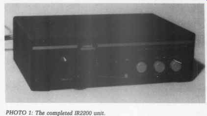
Photo 1
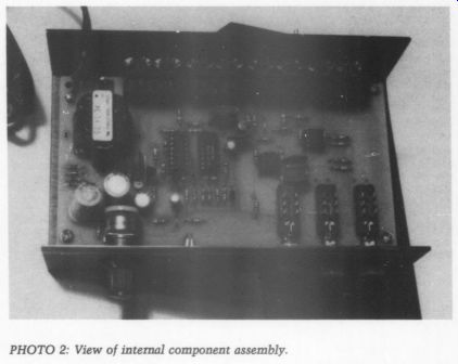
PHOTO 2: View of internal component assembly.
Unit Description
The IR2200 uses the right-minus-left difference (between the two stereo channels) to generate a compensation signal intended to add a sense of ambience to the music. This difference signal is delayed, and its frequency is contoured.
It is then added to the right channel.
Similarly, the left-minus-right difference signal is added to the left channel. With mono signals, there is no difference be tween channels, and thus the unit has no audible effect. The frequency is con toured to minimize the effect of adding the difference signals to the normal output.
The unit has a red LED to indicate that it is on. The front panel also contains three push-button switches and a variable potentiometer that adjusts the level of the compensation added. The first of the three switches (in/out) places the expander in or out of the circuit. The second switch (direct/rec) switches the tape output jacks between a direct connection to the main signal source or to the image-enhanced output. You can play back image-enhanced tapes in the latter position without the expander.
The third switch (tape/source) replaces the tape monitor switch on the receiver The unit does not have an on/off switch, but it remains cool in operation and does not draw much current. You may wish to connect it to a switched outlet on your receiver or preamp so that the expander turns on and off with the rest of your system.
The Reward
By the time I had completed the kit, sent it to the factory and received it back in proper working condition, I was very eager to hear the results of my efforts.
The unit is easily connected to the tape monitor loop of a receiver or preamp.
Sound Concepts recommends that the expander be connected last in a series where other signal processors are being used. This minimizes loss of phase integrity. The article enclosed with the kit includes a discussion of the proper location of your speakers, stating that the best results are obtained by setting each speaker at a 20-degree angle to the listener.
I was pleasantly surprised with the performance of the image expander. I expected some subtle enhancement of the stereo image, but the improvement was readily noticeable and directly related to the amount of compensation added. The best results are obtained when you take a conservative approach toward adding compensation. The image expander has some effect on the frequency response, but it is minor unless a large amount of compensation is added.
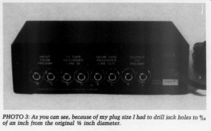
PHOTO 3: As you can see, because of my plug size I had to drill jack
holes to 9/16 - inch from the original 0.5 inch diameter.
With all stereo recordings, regardless of the source material, the expander creates a seamless image that extends at least from speaker to speaker. You might think that your system already does this; that is what I thought, too. I did not realize, however, that the image, while between the speakers, did not ex tend from one to the other. Now it does.
With some source material, the sound even appears to emanate from points beyond the confines of the speakers. I have found that with the seamless and wide image that the expander creates, the sounds almost never appear to be coming from the speakers themselves.
This effect in itself adds to the realism.
Another result of using the expander is an added sense of depth, which is sometimes startling. If, during the original performance, the drums were behind the guitar, that is where the ex pander will place them. Speakers vary in their imaging ability, as well as in their presentation of depth, but I am convinced that whatever your speakers do well, they will probably do better when the expander is properly adjusted.
Of course, recordings vary according to the amount of stereo separation between channels, but the effect of the expander can easily be varied by changing the amount of compensation added.
Many stereo system add-ons that have some effect, particularly in the addition of ambience, are enjoyable in only a small listening area, or “sweet spot, ” as it is often called. I can hear this unit's improvements distinctly from any position on a 7-foot couch facing my speakers. I can also hear them to some extent from most positions in the listening room.
As you can probably deduce, I heartily recommend the Sound Concepts IR2200 stereo image expander. If you have not built many kits, you might want to purchase the factory-built version, as the assembly instructions do re quire some previous experience. I have built many kits and still had some minor difficulties. In either case, I think you will be pleased with the results.
Classic Circuitry


ALL RESISTORS V2 WATT.AND ALL CONDENSERS 400 VOLTS UNLESS OTHERWISE MARKED.
GROMMES HI-FIDELITY MODEL 260A ENG.
A.A HART FEB.27,1958 DWG] D.J.AXELRQD
Courtesy of A.A. Hart, Chief Engineer, Precision Electronics, Inc., who designed and manufactured the Grommes line until 1972.
SHOWCASE
THE SP450 TUBE PREAMP, By Jerry Saunders
I HAVE BEEN INVOLVED in audio for 32 of my 39 years, having built my first amplifier when I was only seven. I had two reasons for building the SP450, the sixth preamp I have built from scratch. First, I had some fresh ideas concerning active circuit and power-supply design. Second, I wanted to use top-quality components, regardless of cost. Little did I know that this project would take more than three months to complete.
My preamp is as large as an ARC D76, measuring 19 by 13 inches and weighing 18 pounds. It contains no circuit boards and has point-to-point wiring through out. I used Teflon-covered, mil-spec, silver wire in the power supply and oxygen-free, copper Kimber wire for the audio internal connections. All the shielded wire is Megacable II.
The power supply includes a power transformer and choke salvaged from a Hewlett-Packard radio-frequency (RF) generator and has extensive RFI filtering before the power transformer. After high voltage rectification, the circuit branches out to three feedback regulators, which provide excellent load and line regulation. Each of these has an adjustable out put (+ 100V), which allows me to fine tune the B+ parameter. Three 24V adjustable IC regulators provide filament power for the 12 tubes. All six power sup plies use Mallory computer-grade electrolytic capacitors throughout (see photos).
For coupling capacitors, I used REL Wonder Caps, each of which is bypassed with a Siemens styroflex polypropylene. I chose Resista metal film resistors. In my opinion, these are the best resistors and capacitors available. Input and output connections are made at the rear of the preamp via Tiffany connectors.

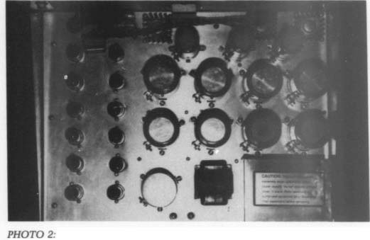
Photo 1
PHOTO 2: Top view of the unit. Notice the 12 tubes and computer-grade electrolytic capacitors. Mr. Saunders has also included test points for the power sup ply near each of the large transistors.
The volume and balance controls are stepped attenuators, and the remaining switches have low-loss gold contacts. I wanted to avoid running any wires with AC near the active circuitry, so I designed the preamp to turn off and on via a relay with a low-voltage DC coil. The relay is located under the power transformer. I used a single diode, resistor and capacitor to drop the 110V line voltage to the 24V DC needed to operate the relay.
The preamp has one phono and three auxiliary inputs. The front panel includes a rotary switch, which allows you to choose among the three auxiliary inputs, and another switch to choose between phono or whatever input is indicated by the auxiliary switch. This two-switch arrangement provides extra flexibility, while reducing possible noise known to occur in rotary switches. The remaining three front-panel switches are power on/off, stereo/mono and bypass/normal.
The last is used to “bypass ” the entire line stage, providing a little extra detail along with a subsequent loss in gain.
This switch also serves as a mute switch when used at normal listening levels
My design runs the 12 dual triodes with very large plate resistors (400k), while keeping the rail supply very high (475V). I chose this setup because triodes operate most linearly under these conditions, allowing for a very low distortion amplifier (Brian Clark, “Tubetorial Series One, Number Three,” The New Testament, January 15, 1981). The circuit uses a common-cathode, grounded grid topology. It contains two cathode followers, one after each of the two main sections. The first six tubes comprise the low-level section, where both halves of each tube are wired in parallel, providing a little extra gain and lower tube noise.
Having established freedom from noise in the phono (low-level) section, I used only one half of each dual triode in the line section. Tube life is about three years.
The sound is detailed, seamless and three-dimensional, with no real signature. No audible tube noise or hum is present at any level. Bass is firm, deep and well-defined, while highs are ex tended and clear. As for the midrange, my Quads have never sounded so good. I have compared my unit with the Bering TF10, the ARC SP-6, 8 and 10, the Super PAS, the Counterpoint, and the Mod Squad Spatial. If you could take the midrange and highs of the SP-8 and marry them to the bottom end of the Spatial, you would approach the sound of my preamp.
Why do I call my preamp the SP450? Well, the SP stands for Saunders Preamp, and 450 is very close to the number of dollars it cost me to build what I consider my finest preamp to date.

PHOTO 3: Rear view of the unit. Note the use of Tiffany jacks. Unused
inputs have shorting plugs inserted in them. The choke and power transformer
are to the

PHOTO 4.
Letters
CORRECTION:
POOGE-3 Two corrections to my “POOGE-3 ” article (SB 4/85, p. 39) are needed. First, on page 40, third column, last paragraph, the first sentence should include a comma between the name Miller and the name “early..., ” [the name Early should have been capitalized] to prevent confusing the two. Both effects con tribute to increased distortion. Second, the Fig. 6 caption was incorrect and should be ignored. It should have noted that the input could also be arranged to accept balanced inputs with the R chosen to properly terminate the line.
R.N. Marsh Livermore, CA 94550
COLLOMS CRITIQUE
I Have every issue of Audio Amateur published. While you've published some ridiculous articles in the past, you have reached a new and probably un-matchable nadir with the Colloms article in the 3/85 issue.
Based upon the article content it is inconceivable that Mr. Colloms has any idea how to conduct a test on a piece of equipment. If the article were an editorial, I might let it pass, but it has been presented to us as a critique of the state of hi-fi by an expert in the field. As such, the article should at least follow some semblance of reasoning. There is not one substantive statement in it, which contains an attempt at logical persuasion or cites a reference. Instead, the reader is asked to take on faith obvious nonsense.
The following are quotes from the article with rebuttals:
1. Regarding the successful crossover of equipment amplifier techniques into audio amplifiers- ”Many designers still believe this to be true, but few reviewers still hold this viewpoint...” A few references would be in order here, but does it matter? Unless the reviewer were an electronics expert, on what basis should his opinion of circuit design be of value?
2. Should amplifier quality remain relatively static, or should it, as I believe, continue to improve.... Without defining quality of improvement this is meaningless. Once amplifiers have sufficient power to handle the desired load at full volume, and gain no audible benefit from changes, what constitutes progress?
3. “A few years ago, well-organized testing under rigorous conditions suggested that sound quality differences be tween then-accepted “good” amplifiers were small enough to defy statistically verified identification. With hindsight, I must accept that the standards set then for the test in terms of reproduced quality were probably not high enough. What was the basis for this 'hindsight'? What were the test conditions and why aren't they still valid?
4. “...the more listening tests I have undertaken, the harder it appears to be to set up a controlled statistical test for sound quality. If amplifier differences are to be readily observed, significant differences must be present in the first place. ” This is mind boggling. Did it not occur to Mr. Colloms that the simplest answer is that there are no significant differences left. Instead Mr. Colloms claims that the tests no longer are adequate. What a pre-judgment.
5. “...all my listening ... has only rein forced my conviction that amplifiers do sound different in many important respects...Even though only a portion of my recent listening has included limited blind or double-blind testing, where this has taken place, it has strongly con firmed the results obtained from sighted testing. ” What were the test conditions? What was the equipment? Why should I take this on faith without any data?
6. “...many of the long-accepted features favorable to design and performance are not invariably associated with the most successful examples of the designer's art. ” What are these features? What was the equipment in question? On what basis was the design iconoclastic and also successful?
7. “This discussion will also be backed by many examples of proven quality established by careful auditioning and lab testing. “ There follows in the article a lot of name dropping, but not a single reference to a lab report or a listing of performance data. There is not even reference to a review article. The equipment cannot be considered “proven ” on this basis.
8. “As the state of the art is approached, however, the established rules start to break down. ” What rules? Does Mr. Colloms imply that Ohm's law does not work in top quality equipment?
9. “The recent results concerning the sound quality of copper wire with an improved crystalline structure indicates that the wire and circuit copper must also be taken into consideration. There have been claims about the values of oxygen pure copper etc., but that is all. Let Mr. Colloms produce some statistically significant data showing an audible improvement with changes in copper quality.
10. It should be possible to set up a comparison of two identical high quality amplifiers, fitted into sealed black boxes. Based on the inclusion of just two components to one box, namely a coupling capacitor and a length of wire, and their omission from the other, it should be possible to demonstrate significant sound quality differences. The assumption of two audibly identical amplifiers negates Mr. Colloms' own argument. In any case, no competent tester would consider the proposal. A single amplifier should be used with the components switched in and out of the circuit.
11. “Taking HFN/RR's (Hi Fi News & Record Review) current critical standards, suppose the power amplifier without the components scores 70 percent; recent data would indicate that the likely outcome for the other model with the extra passive components is likely to be a reduced rating, probably around the 60 percent level. Yet the amplifiers are basically identical in electrical terms.”
What critical standards? They can't be very critical if Mr. Colloms considers adding parts to a circuit does not constitute a negation of electrical equivalence. Doesn't Mr. Colloms know that science is based on the experimental method? He cannot propose a test and expect a reader to accept imaginary results as the basis for a won argument!
12. “An average amplifier contender rates at 50 percent based on past experience of perhaps 150 to 200 models. ” Does this mean that reviewers rate equipment by memory alone? Anyone who has listened to audio equipment knows that memory for sound is almost nonexistent. A reference for direct com parison must be used. Therefore, to compare the latest device to the first of 200 when both are noticeably worse than the current reference cannot be done, and a percentile rating system is a farce.
13. Mr. Colloms discusses a variety of amplifier design techniques showing that designers with conflicting advertising claims can all produce top quality equipment. I quite agree, but how does this fit in with the previous arguments of inadequate reviewing procedures. It merely reinforces the point that amplifiers have reached such high quality that no significant audible improvements are likely in the area of amplifier circuitry.
14. “...it is possible to establish a link between poor sound quality and high negative feedback.... Some of the best sounding products in their respective price categories use very low levels of negative feedback (0 to 20dB), whereas most of the worst have incredible specifications primarily based on high feedback.” This is supposed to be a logical conclusion? On what basis should the reader believe that the bad sounding amplifiers sound bad because of their negative feedback instead of some other reason like a defective power supply? I see no attempt at presenting a link between bad sound and high negative feedback.
15. 'Recently, a team of skilled listeners examined the effect of the small output inductor present in almost all transistor amplifiers. When in place as normal, a given sound quality was established and noted by the team. The inductor was then deleted and the unit re-auditioned.' This is in the nature of an apocryphal story. What were the test parameters? How long did the change over take? Did the team know whether the inductor was present or not?
16. “There is now a good body of evidence to indicate that the majority of commonly used tests and specifications are of limited value in quantifying sound quality. Despite the increasing power of laboratory test equipment, the association between measurement and sound quality seems to be on the decline rather than the ascent.” I would love to see some of this evidence, and what common test and specs are we talking about? Will it never occur to Mr. Colloms that when differences in equipment become minuscule they eventually become irrelevant and therefore can't be correlated?
17. “We are presented with the technically absurd result that a top-class analog turntable playing a top-quality disk can still sound marginally better than the compact disk (CD) equivalent.
By all the amplifier-related specifications, the CD reproducing chain is in finitely superior to the vinyl alternative, yet our ears may tell us otherwise. ” If the disk recording were identical to the vinyl, which I grant only for the sake of argument, it is blazingly clear that a more accurate reproduction of a margin al recording could sound worse than one which blends together and thus hides the small defects. Need I say more?
18. 'How can a meter or two of ordinary audio cable affect sound quality more than the insertion of a complete preamplifier line stage in a given audio chain?' As long as we are playing guessing games, let's assume that the preamp stage is a good design while the audio super cable has such high capacitance that it destabilized the amp output stage.
19. “The published specifications of an amplifier is of little value in deter mining its sound and even fails to tell us how loud it is going to be. Indeed, many aspects of established specifications may actually be harmful to the production of good sound. ” Some facts, let's have some facts not just claims! And must I throw out my sound level meter because the manufacturers are lying, or was it the laws of electronics that were overturned?
20. ...it seems that the designer's personality, taste and character matter more than his choice of technology.
Good hi-fi is more the product of an experienced craftsman than the intellectual creation of a theoretician. Unless you want Danish modern hi-fi equipment the reader would be well advised to buy from the electronics expert rather than Mr. Personality.
21. 'Both Malcolm Hawksford and John Atkinson have pointed out that speech and music are discontinuous random signals...’ If these signals were random they could convey no meaning. On the other hand, I am certainly having trouble finding the meaning of this article.
22. “During some 40 years of very ex pensive development, the transistor has not yet beaten the tube in reproducing music when judged at the highest quality level.” This is opinion not fact. We don't even know whose opinion. Mr. Colloms' opinion, someone elses?
23. In short, I ask the Editor (and any reader) would you buy a sound system from Mr. Colloms?
24. Many of the articles in TAA have been superb. Why do you publish articles like the one by Mr. Colloms?
Robert GAULT; Grosse Pointe Woods, MI, 48236
Mr. Colloms replies:
When I first began to read Robert Gault's letter, I thought it was a practical joke, but soon realized that the writer was in deadly earnest. I was however surprised at the degree of animosity that his 'destruction' of my article appeared to contain.
Nonetheless he does raise several points that need answering, but before I attempt to do so, I should like to make a few preliminary observations.
The article in question was originally printed in Hi Fi News & Record Review as part of a continuing series of subjective observations and lab tests, which have been appearing over the past decade. An academic article was not appropriate, and as it stands the content was, in my view, well supported by the bulk of my published work in both HFN/RR and Hi FI Choice. Unfortunately I had not fully appreciated the consequences of the isolated publication of the material in TAA.
I absolutely refute Robert Gault's accusations relating to poor scientific method, and his comment concerning “obvious nonsense” presented as evidence.
I explained earlier that a list of references would not have been appropriate for inclusion in HFN/RR, but this is not to say that they do not exist; rather my problem in answering Robert Gault on this point is just where to start. To date I have published over 1500 equipment reviews of which less than 15 have not been backed by comprehensive laboratory tests to a standard that usually exceeds that offered by most manufacturers. My supporting technical articles now number around 50, and I have also reviewed secondary items such as passive components, platforms and cables.
I have used, and continue to use, blind and double blind methods for subjective evaluation, and around 70 percent of my published output is based on such. How ever, as I have been accused of not pro viding sufficient evidence, let us quote specific examples. Let us take an issue of Hi Fi Choice 'Loudspeakers'. For the listening tests, all conducted under blind conditions, at least six panelists are involved in a total of some 6000 separate presentations, the latter comprising distinct assessments of sound quality on a particular program excerpt. Each of these assessments includes a numerical score, backed by a written commentary covering major aspects of subjective quality, such as perceived frequency response and tonal balance, coloration, stereo accuracy, clarity and distortion.
I do, however, admit that the original article could have been written with greater precision, and I feel the best way to resolve any questions that have arisen is to take Robert Gault's points one by one.
1. The majority of UK reviewers do find that amplifiers sound different model to model, and several of these reviewers are themselves electronics experts. Many skilled audio circuit de signers throughout the world will con firm that circuit design per se cannot be used to predict sound quality, despite following sound textbook theory of the designed equipment performing with ex pected precision under lab testing. For example, the work of Jung, Marshall Leach, the Levinson team, the Sony Esprit team, Curtis, Bill Johnson, Bill Conrad, Matti Otala, Stuart, Vereker and Azima to name but a few can be cited-surely Mr. Gault does not wish to take exception to all these!
2. Since Mr. Gault has already decided that amplifiers cannot differ subjectively I cannot answer his objection here.
3. The tests referred to involved the Quad amplifier and were carried out first by James Moir sponsored by Quad (Acoustical Manufacturing Ltd.) and then subjectively by myself, sponsored by HFN/RR (Jan., June, Nov. '78). These must be read for a full appreciation of the criticisms and limitations. Subsequent tests have shown that great care needs to be taken with sound quality of all the supporting equipment in order to observe the test variable-in this case, the power amplifier quality.
Furthermore, single subject auditioning is advisable, to reduce spurious influences. There is insufficient space to go into my favorite technique, first pro posed to me by Laurie Fincham (KEF Electronics), namely that of single presentation. For most subjects it beats A/B or ABX testing. In my experience this has proved to be the best analytical test for the subjective assessment of amplifiers. (See HFN/RR May '85 for John Atkinson's use of this to identify Sony PCM-F1 in the 14-bit mode.)
4. I should clarify this point by explaining that I was covering the classic A/B group tests (as outlined in 3) and not including subsequent methods.
5. Please don't take my opinion on trust-read my previous test results.
Every part of the printed HFN/RR article is based on published work, not idle speculation.
6. Surely I discussed the majority of favorable design features in the article? Class A, A/B, etc; power supplies;
bipolars; FETs; tubes; double mono, and so on.
7. All amplifiers mentioned were fully lab tested, (see back numbers of HFN/RR over the past eight years, as well as Hi Fi Choice and Hi Fi For Pleasure).
8. Heaven forbid that I should deny Ohm's law. My comment concerns the fact the application of Ohm's law by rote does not answer all the questions, because hardly any part of an audio amplifier is defined by Ohm's law, except at the basic level. The complex inter-relationship between non-linearity, the variation of different parameters with frequency and voltage plus hysteric energy loss and storage in components means that Ohm's law will only define the most simplistic model of circuit operation.
9. In its December '85 issue HFN/RR will publish the results of tests on cable sound quality. Based on a specific part of that test, the results show that for two matched cables, where the only variable was the crystalline structure of the cop per conductor, a noticeable difference was heard, and by my standards, represented a significant improvement.
(Hawksford's article in HFN/RR Aug. '85 shows that Ohm's law, too, does not fully describe the process.)
10. This test was done (HFN/RR Jan. '85). The amps were identical and had been extensively measured as well as comparatively auditioned prior to the test in question. A statistically valid difference was obtained due to the insertion of the input capacitor alone (the 3dB high-pass point remained several octaves below the audio band.)
11. The test was done!--see 10.
12a. I do not agree that sonic memory is almost non-existent. Memory of small A/B differences is certainly weak, but one's judgment and appreciation of a good musical performance is not. Other wise we would have many lousy orchestras and good musicianship would be a waste of time.
12b. Control, reference amplifiers have been held in my stock for many years to maintain a consistent scoring standard as new models are reviewed. The percentage rating system is appropriate and understandable to the lay reader, and it works.
13. (See 6.) Note again in my argument that expert but conflicting circuit design techniques have been claimed as responsible for high audio quality, and yet the results of commercial practice show little sensible correlation between them, and perceived sound quality.
14. Here I must ask you to accept my experience in regard to lab testing and subjective evaluation of amplifiers. In general the highest overall feedback, lowest distortion amplifiers have sounded the worst, and within sensible limits of source impedance and distortion (< 0.1 percent), the amplifiers with the lowest overall negative feedback have sounded the best.
15. Briefly, two matched test amplifiers were used. One was modified, and the pair then re-auditioned without identification as to which was which.
The changeover time was a couple of seconds.
16. In regard to several parameters, e.g. linear power, I did explain the assoc iation with sound quality was weak.
Refer to my past technical reviews for the evidence.
17. Here Robert Gault should say more. For anyone who appreciates music, be it reproduced or live, better is better, and is unmistakable. There is not space here to expand the discussion of dimensionality.
18. Let us not guess, Robert. The Belden coaxial cable had very low capacitance, 30pF/meter, and it did affect the sound quality more than the ARC SP8 line stage.
19. See 14.
20. I think there is some misunderstanding here. I referred to craftsman ship in electronic design, not styling, though I am happy to have that well designed too. (See the anonymous letter in HFN/RR Aug. '85, p. 15, for an expansion of this argument-designers must care.) 21. My apologies-the word 'random' is spurious, and discontinuous is quite sufficient.
22. No problem-many peoples' opinion, including my own. Will those in favor please write.
23. I don't sell sound systems.
24. Because they deserve to be read.
P.S. For UK disbelievers, I have frequently run controlled listening tests, often when a manufacturer contests a review opinion. They are often surprised by their judgments when made under controlled conditions, but are usually willing to accept the outcome.
GOLDEN EAR GOSPEL
Once upon A TIME, 2 few people who were more interested in music than electronics noticed their transistor amplifiers sounded inferior to their old tube equipment. They began to question the measurements published in the commercial hi-fi rags that indicated the opposite. These people became known as the Golden Ear audiophiles Then, along came an engineer who stayed awake in his systems engineering class. He noticed that audio equipment was being tested only for steady state response, which is only a half truth. He started testing amplifiers for their time-domain response and the phenomena of slewing induced distortion became known to the world of audio.
Now that objective proof was found that the Golden Ears were correct in criticizing the sound of those transistor amplifiers, they patted themselves on the back and began spreading the gospel of the Golden Ears, which says, 'When subjective impressions conflict with scientific evaluations, the Golden Ears are correct because the scientists have not yet found the correct test to verify what they are hearing.' Some audiophiles realized that the problem was not a failure of science, but a failure of audio publishers to include facts that might offend advertisers, and they started new subscriber supported magazines that provided an outlet for subjective opinions. Unfortunately, fear of offending advertisers was replaced by fear of offending subscribers, and editors quickly chose sides in the debate leaving no middle ground. The Golden Ear believers never considered that the measurements that gave them credibility in one place could also prove them wrong in another place....
I have no dispute with testing audio equipment by using the listener's subjective reactions as a basis of quality. I have taken part in many of these tests.
After all, the object is to create the “illusion” of a live listening experience.
However, the listener's reaction to the escutcheon plate has no significance to the subject of music reproduction. Subjective testing does not have to be un scientific. Electronic trickery is an acceptable method of dealing with the physical constraints of the listening room and a limited number of channels.
This is one case where the end justifies the means, but this does not include brainwashing by Golden Ear publishers.
That is not an acceptable method of re creating the listening experience because it limits the enjoyment of recorded music....
I gained several years of enjoyment from Audio Amateur while it was directed toward the audio craftsman, but the worthwhile construction articles are becoming a rarity. Now, you are asking me to have faith in capricious un substantiated opinions. This is not craft or science: it is religion. Since you have been seduced into the religion of the Golden Ears, audio craft has been displaced by crafty audio. These authors that think they hear the effect of oxygen free copper have been breathing too much oxygen free air.
First publish statistically verifiable tests that others can duplicate, and I will be willing to read their articles.... You, dear emperor of Audio Amateur, are wearing no clothes. If you continue to fill your pages with the [writing of people] like Martin Colloms, who hear the differences in amplifiers with their eyes, I will not be supporting your tailors with continuing subscribership.
Dennis L. Green; Detroit, MI 48235
The Editor replies:
I have edited Mr. Green's letter in several places eliminating some comments about those he disagrees with, and removing some unwarranted name calling. Mr. Colloms' credentials are as extensive as anyone writing about audio today and he certainly has a right to be heard, even by those who think he is mistaken. Mr. Colloms' judgments are based on double and single blind tests, by the way, as the reader will see reading the Colloms response to the Gault letter.
If the construction articles in the last three years of Audio Amateur fail to meet Mr. Green's standards for being “worthwhile ” then I can think of 25 or so authors who will be not just a little surprised. Mr. Green is, of course, welcome to exercise his right not to read Mr. Colloms, or to cancel his subscription, if the magazine does not fulfill his needs.
Mr. Green's letter makes it clear that he is angry at those who give credence to subjective evaluations of audio equipment, and at editors who publish those writing about them. But that is all it does make clear, unfortunately. Heaping scorn on those with different view points usually means the contender can't think of anything else to do with his frustration.
Now, I must go see a man about a barrel. -Ed.
GALO vs. DD
[...] umn, stating “a belt driven turntable with a heavy platter ” is smoother, is clearly incorrect. That is no reason why a direct drive turntable should not have a heavy platter (mine has). If both have similar platters the results are likely to
be indistinguishable. Most belt driven turntables require a spring suspension because the drive motor's high speed of rotation can cause possible vibration.
With direct drive the rotation speed is very low (33.333 - 45 rpm) and there is virtually no vibration or rumble from the platter bearing, that is common to both types.
My own turntable is a Garrard DDQ650 (quartz-crystal controlled), and I can assure Mr. Galo that even when the gain control is advanced to 20dB beyond normal, using an unmodulated test record, there is no rumble. How many belt drive models would pass this test? To prevent acoustic feedback or floor borne vibration all that is needed is a plastic foam “pillow, ” which I suggested in TAA a few years ago.
G. WOODVILLE; Aylesbury, Bucks. , England HP17 9LW
Mr. Galo replies:
Mr. Woodville obviously believes conventional measurements tell us all there is to know about turntable performance, and that beyond the established measurements, no audible differences exist.
I do not agree with this view, and neither do most of the writers for the non-commercial (i.e. underground) audio press.
Clearly there must be a reason why the vast majority of high-end turntable manufacturers have chosen the belt drive approach (consider the Linn, Oracle, Sota, Ariston, Thorens and new AR turntables). The superior isolation from acoustic feedback that a 3-spring belt driven turntable provides is a prime factor in their superior sound quality.
Mr. Woodville is correct in pointing out that the spring suspension isolates the platter from the motor's vibrations, but he misses the most important point: the spring suspension provides highly effective acoustic isolation.
The smooth rotation of a belt drive turntable is probably due to more than just the use of a heavy platter, as I pointed out in my paragraph 5 on p. 27.
Indeed, Linn Sondek has spoken of the possible frequency modulation problem due to the constant corrections that take place in a direct drive turntable.
I disagree with Mr. Woodville's statement that there is virtually no vibration from a direct drive phono motor. I agree that the slow speed of rotation provides very few audible vibrations, but direct drive motors do produce vibrations in the infrasonic region, which can excite arm/cartridge resonances, if the arm/ cartridge resonant frequency is at, or near, the frequency of the infrasonic vibrations from the motor.
Mr. Woodville implies it is not possible to build a belt driven turntable with a bearing as quiet as that found in his direct drive turntable. I am at a loss to explain how he arrived at this conclusion. Besides, audible rumble should not be a problem with any high quality turn table of either type of design. Other factors, covered in my article, account for the sonic differences.
I have had very poor luck using the foam pillow arrangement that Mr. Woodville mentions. The foam is not compliant enough to isolate the turn table as effectively as the spring method.
Incidentally, one direct drive turntable, the French Goldmund, does have a very compliant spring suspension, which undoubtedly has a great deal to do with its outstanding performance. The implementation is expensive however (the Goldmund sells for around $2500).
I suggest that Mr. Woodville read some of the material referred to in my list of references, particularly the articles by Andrew Benjamin and John Horan. They should reinforce some of the points I made in my article and in this letter.
VOLTAGE REGULATOR ROUNDTABLE
IN my schematic of a high-voltage, low impedance voltage regulator (Fig. 1), I have taken the standard Jung 317-type high-voltage regulator and have incorporated the Sulzer-type regulator. The Sulzer regulator would be floating and would receive its operating voltage from the 30V zener in the 317 zener string. The output voltage (Vo) of the whole circuit would be the floating voltage (270V) plus the Sulzer voltage, V, (R3/R4 +1). V, is 290.7V DC with the zener values shown.
I would like some feedback from other audio amateurs on this idea. Christopher Paul has an excellent idea on high-voltage, low-impedance regulators (TAA 2/84, p. 25), but I do not like having to build the complex supply for the floating opamp.
With the circuit shown, I have to supply only one voltage, which is the operating raw DC.
R. HURLEY
Texas City, TX 77590
James Boak replies:
The regulator scheme Mr. Hurley proposes has the potential for outstanding performance as a low-impedance source, although it would have some weaknesses as an absolute reference. As it stands, however, the design shares several problems with many of the high-voltage regulator schemes published in TAA, including my own.
First, the reason the regulator would suffer as an absolute voltage reference is that the 270V zener reference would have a fairly hefty shift with ambient temperature. It would also tend to self heat, as it would be sinking the power used to drive the NE5534, as well as the 5 to 6mA of LM317T idle current. Device types are not specified, but I assume 5W devices here. Each device would generate about 1W at idle, which would result in a gradual drift of output voltage after turn on until the unit warmed to steady state.
Second, the design must be protected against damage during transient conditions, especially during turn-off. Using a 6.8V zener to guarantee a fixed and nearly ideal voltage across the LM317T for the desired output voltage (presumably about 1.2V) is a good idea, and the shunt diodes would protect the IC from reverse-bias conditions on power-down.
Unfortunately, the same cannot be said for the NE5534 and TIP50 (marked TR2 in parentheses in Fig. 1), which make up the actual output regulator. When power is removed, if there is no load to discharge the 600uF photoflash on the output, it will tend to remain at 300V DC. The collector end of the TIP50 will be connected to near-ground potential through the 1N4007, which protects the LM317.
if the TIP50 could withstand the 300V reverse emitter bias, another problem would develop. The NE5534 power lines are connected to the same ground potential through the 1N4004, which shunts the output at the LM317 (marked D2 in parentheses in Fig. 1). The zener voltage for the base-emitter function of the TIP50 is about 7V, and the internal structure of the NE5534 could not withstand any differentials in excess of 40V for very long without serious damage. The potential for problems with 300V available is substantial. Put ting another 1N4007 between the emitter and collector of the TIP50 (cathode to collector) would prevent a large reverse differential voltage across the NE5534 or TIP50. I have added a diode marked D3 in parentheses in Fig. 1 to provide this shunt.
Finally, two active regulators floating against each other and controlling a dynamic load are prone to oscillation because each is in the feedback loop of the other. The solution to this problem is a careful layout and perhaps the addition of some shunt caps around the NE5534's power leads. This problem is often best solved by experimentation, but apply a load that covers the same frequency range as the final system load to be sure the supply is stable. Do not forget to look for large excursion sub sonics. When you have big caps inside the feedback loop, there is the opportunity to generate some pretty slow stuff (2Hz or lower is often seen in similar designs).
With solutions to these problems in mind, the design should perform pretty well and has the potential for a very low impedance output. Good luck with it.
Michael Sulzer replies:
I have just one comment concerning Mr. Hurley's high-voltage regulator. The reference in this circuit is actually the voltage of the zener diode string plus the high-quality reference derived from the output. The former is not as good as the latter, but because it is derived from the ...

FIGURE 1: Mr. Hurley's high-voltage, low-impedance voltage regulator
design. James Boak supplied the information in parentheses and an addition
indicated by the dotted line.
...reference current of the 317, it may be good enough for most applications. If this is so, the circuit can be simplified by replacing the 30V zener with two zeners that sum to 30V in series and using the junction of the two as the reference. The output can return directly to the negative input of the 5534. The positive input should be decoupled from the junction of the zener pair with R and C. In any case, it would be best to use a high-voltage capacitor from the positive input and connect the low end to ground. It may be necessary to protect the op amp inputs with diodes to its power supply connections.
VIA COLLOMS & CRUCE
I am impressed with the content of Audio Amateur, in particular with two outstanding articles in recent 1985 issues. “The Great Preamp Shootout' by William L. R. Cruce, in issue 2/85, tackled a difficult task with integrity, lucidity and convincing detail. How fortunate we readers are to have such knowledgeable and dedicated people, who also have considerable communications skills.
“The Sound of Amplifiers ” by Martin Colloms, in issue 3/85, is another excellent article that has added substantially to my understanding of what constitutes significant criteria applying to audio power amplifiers, and to the difficulties involved in the subjective evaluation of their “sound quality. ” My thanks to you and to the editor of Hi-Fi News & Record Review, for permission to reprint Mr. Colloms' article.
I feel I have hit the jackpot. These articles, plus all the other information in TAA have given me much to think about. I've already renewed my subscription for the next three years.
R.E. HENDERSHOT; Scarborough, Ontario Canada M1E 4Y2
QUATRE GC500 INFO NEEDED
I Have a Quatre GC500 power amplifier and need a schematic for it. Does anyone have a source for one? Or does anyone know where I can find Charles Booster or Ed Anderson, engineers on the Quatre Gain Cell Amplifier.
Reep HURLEY TPN Company; Texas City, TX 77590
CAPACITOR CHATTER
I HAVE BEGUN BULDING ten of the Sulzer power supply regulators (TAA 2/80, p. 8) for inclusion in as many of my components as possible. I have noticed, however, that Fig. 4b, which is the stuffing guide for the regulator circuit board, does not show polarity on four of the tantalum capacitors--C4, 1uF, 35V; C5, 4.7uF, 35V; C11, 1uF, 35V; and C12, 4.7uF, 35V. Since a number of builders will likely use tantalum bead capacitors, they should be advised that tantalum beads installed with the wrong polarity are potentially dangerous. They will often violently self-destruct with a miniature explosion that could damage the builder's eyes.
The correct installation of these caps is as follows: C4 and C12 with the positive lead toward the output end of the board; C5 and C11 with the positive terminal toward the input end of the board. Tantalum bead caps are marked on the positive lead with either a plus sign or a dot, usually in red.
Anyone who has wanted to build the Sulzer regulator, but has been put off by the cost of the tantalum caps, especially the 47uF, 35V device (cardiac arrest!) should get a copy of Diamondback Electronics' catalog ( PO Box 12095, Sarasota, FL 33578). Diamondback offers a wide range of US-made tantalum caps at unbelievably low prices-4.7uF, 50V at 37¢ each; 47uF, 35V at 75¢ each.
While I am on the subject of capacitors, if anyone knows of a distributor for TRW X363UW or TRW 35 polypropylene caps, please let me know. The polypropylene caps for Dick Marsh's head amp cost nearly $70 from IAR. I would like to build the Marsh preamp, but at those rates, it will take nearly $200 worth of polypropylenes.
Nobody ever told me topnotch sound came cheap, but WOW!
PauL T. Key Fort Wayne, IN 46815
Editor's Note:
The tantalum capacitor symbols in Fig. 4b (the stuffing guide) of Mr. Sulzer's article are shown correctly (i.e., with the straight bar indicating positive and the curved bar negative) except for C4 and C12, which should be reversed, as Mr. Kelly points out. In the schematic (Fig. 3), C4, C5 and C12 are shown with correctly oriented symbols (although C4 lacks a plus sign at the positive end), but C11 is shown incorrectly .
Just Looking
Nady Systems is now marketing a new infrared cordless stereo headphone.
Now music and video lovers can en joy the privacy, and full range stereo sound provided by headphones un tethered. The system consists of two parts: an infrared stereo transmitter plugs into any headphone jack, and an infrared signal is transmitted to a sensor on top of the cordless headphones.
The system features a frequency response of 50-15kHz and a range of about 35 feet. It's also useful as a cordless headset studio monitor, and as a TV listening device for the hearing impaired.
For further information contact Nady Systems, Inc., 1145 65th Street, Oakland, CA 94608.
As of December 1, 1985 Phoenix Systems' products will be manufactured (under license) and distributed by Rhoades National Corporation.
A combination RHOADES/PHOENIX catalog can be requested by writing Rhoades National Corporation, Dept. R/P, PO Box 1316, Columbia, TN 38401 or by calling (615) 381-9007.
The Winegard Company has introduced a portable home satellite TV receiving system, the Mini-Ceptor, and RF-102 and RF-90 Satellite TV Receivers with block downconversion.
Mini Ceptor RR-646 is fully portable, meets most zoning requirements and is priced under one thousand dollars. It includes a powder coated, six foot, perforated aluminum dish antenna, an RF-90 receiver (see below) with tunable audio for satellite radio reception, satellite format selection, polarity control, a signal strength bar, AFC, switch able modulator, a 60 foot cable and a weather cover.
The RF-102 and RF-90 provide excellent audio and video reception. The RF-102 offers performance and convenience features to audio/video buffs. It has a seven function infrared remote control with built-in stereo processing and built-in antenna positioning control.
In addition to receiving satellite TV, the unit's tunable audio circuitry captures radio programming also beamed from the “birds. ” The RF-90 also includes block down conversion, but offers a smaller budget, no-frills receiver. The unit includes a switchable modulator, antenna coupling, satellite format selector, signal strength bar, audio output, AFC, one modulated RF output and one raw video output and it's Ku band (12GHz) compatible.
For more information contact the Winegard Company, 3000 Kirkwood Street, Burlington, IA 52601.
More from Analog Devices: the 12-bit Hybrid A/D Converter, the HAS-1204, and Application Note literature.
The A/D Converter (ADC) provides an internal track/hold (T/H) amplifier and a maximum conversion rate of 500kHz. The HAS-1204 also includes the necessary timing circuitry to per form a complete conversion without any external circuits. Combining the ADC and the T/H function in one package reduces design and characterization efforts, board space and helps to achieve top performance.
Analog calls it the smallest self contained 12-bit converter (40-pin metal DIP) available capable of 2us conversion time.
The free four page Application Note is a guide that describes methods for simultaneously generating up to four different analog waveforms from one chip. Highlighted in the application note is an example of how to generate a 3-phase sine wave using Analog Devices' AD7226 four-DAC converter, an EPROM, and other support components.
Diagrams included in the note illustrate a 3-phase sine wave output, out put waveform spectrum analysis and other variable output waveforms such as square waves and triangular waves.
Inquiries for further specifications on the HAS-1204 and the Application note literature should be directed to Analog Devices Literature Center, 70 Shawmut Road, Canton, MA 02021.
Bicron Electronics Company […] to 2500VA, are one half the size and weight of conventional power trans formers and built with either open construction or encapsulated with terminal block.
The “donut ” core is a continuous strip of grain oriented, silicon steel, wound at a controlled tension that results in a stacking factor of 95 percent of theoretical weight and eliminates most air gaps. Bicron claims their toroidal transformers can replace most traditional transformers, in most applications where size and weight are a problem.
Available separately is an application guide, “How To Design Your Next Power Supply Using Toroidal Power Transformers. ” The guide offers specs and application ideas.
For more information contact Bicron Electronics Company, 100 Barlow Street, Canaan, CT 06018.
The DB-6A, in production for over six years, is an advancement of DB Systems' power amplifier. The improvement triples power supply capacitance to 42k uF, giving increased headroom for transients and eliminating power supply ripple for smooth clipping performance.
New features include the 42kuF power supply capacitance, built-in line surge protection and gold plated speaker binding posts and phono jacks.
For further information contact: DB Systems, Main Street, Rindge Center, NH 03461.
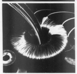

Nakamichi USA Corporation introduces the CR-7A and CR-5A Discrete-Head Cassette Decks.
Both decks utilize Nakamichi's microprocessor-transport techniques, crystalloy recording and playback heads, and low-noise/low-distortion electronics with Dolby IC tracking.
With the CR-7A and CR-5A the user can override the automatic system and choose tape type and equalization manually. This allows use of cassettes that lack keyways and permits optimum equalization in unusual situations.
Their central display panels indicate output choice, Dolby setting and ac curate peak-reading indicators monitor source or tape level over a 50dB range.
Both decks also feature an output level control, independent left/right recording level controls, a master recording level control and the Nakamichi Dual Speed (4-second/2-second) Master Fader.
The main difference between the CR-7A and CR-5A lies in their tape matching systems. The CR-5A has a manual bias tune control to match the tape by comparing the playback sound with the signal being recorded. The CR-7A automatically adjusts bias and Dolby calibration to match the tape being used.
For more information contact Nakamichi USA Corporation, 19701 South Vermont Ave., Torrance, CA 90502.
Rapid Systems announces the digital scope/spectrum analyzer peripheral for IBM, Apple and Commodore personal computers. The peripheral plugs into the computer, and the computer becomes a digital scope or spectrum analyzer ready to go to work.
The digital scope features four channels, sampling rates from 100Hz to 2MHz in 14 steps, adjustable gains from 100mV/div to 20V/div in 8 steps, up to 500kHz analog bandwidth, 2k by 8 data buffer, diode protected inputs, and separate trigger input with adjustable controls. Software features fast menu driven operation, help file, color graphics, keyboarded trigger/gain/time base, zoom mode buffer, active scrolling, grid display, extensive store/retrieve functions, post trigger delay and multi-channel display.
The spectrum analyzer features FFT (Fast Fourier Transform) sizes from 16 to 1024, execution times from 2 sec (16 point) to under 10 sec (1024 point), frequency choices from 100Hz to 500kHz, input voltage from 1.6V p-p, rectangular windows, baseband operation, power spectrum computation, averaging, better than 1Hz resolution and transfer digital scope time series data to the spectrum analyzer for frequency analysis.
For more information contact Rapid Systems, 659 North 34th Street, Seattle, WA 98103.
AUDIO AIDS
AUTO-MUTE FOR DANIEL
SEVERAL READERS have written to express their interest in an “auto mute ” circuit for the “Daniel ” preamp published in TAA 2/85, p. 7. While I agree a mute function is desirable in a vacuum tube preamp, I had anticipated that most builders would incorporate a front panel switch (manual mute) to effect this feature. Nonetheless, the response is sufficient for my reconsideration of the matter. Therefore I have designed a small printed wiring card (Fig. 1) which, upon sensing the presence of unregulated filament voltage (F+ and F-), will mute the output of the preamp for approximately 45 seconds at turn on and immediately at turn off. Since the circuitry derives both power and control data from the F+ and F - lines, no additional wiring will be necessary be tween the master power supply and the preamplifier enclosure.
I have also included a copy of the circuitry (Fig. 2a) and a parts list should anyone desire to fabricate the circuit without the benefit of a PCB.
J.J. Curcio; State College, PA, 16803
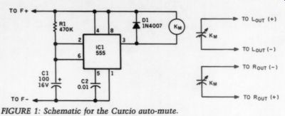
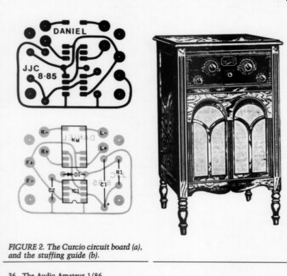
FIGURE 2. The Curcio circuit board (a), and the stuffing guide (b).
FIGURE 1: Schematic for the Curcio auto-mute.
-----------
PARTS LIST
Capacitors C1=100gF/16VDC C2=0.014F/25VDC
Diodes D1=1N4007 Misc.
IC1=LM555CN Kn=12VDC, DPDT
----------------
Although designed for 'Daniel' the auto-mute circuit is suitable for any preamp. If readers express enough interest Old Colony will offer the auto mute circuit as a complete kit or a printed circuit board only. Prices are estimated to be $5 for the PCB and $15 for the complete kit. If you would like OCSL to offer the PCB enter #870 on the Fast Reply card. If you are interested in a complete kit enter #875.
-----------------------
TUNER DIAL RESTORATION
ONE of THE PLEASURES Of hi-fi is the trading and bargaining that accompanies trans actions between private owners. One person's junk is another person's treasure. By means of such a transaction, I acquired a 15-year-old Japanese-made Monarch ST-50X FM stereo tuner with a power supply problem.
As I started working on the unit, I noticed that it was coated with a greasy film, so I decided to clean it before proceeding with my repairs. Some Fantastik spray cleaner, followed by a thorough rinsing and drying, did a great job of restoring the front panel, chassis and cover to a factory-fresh appearance. The glass dial plate presented a problem, however. The film covered both sides of the glass, giving it a smudged, fuzzy appearance.
The lettering on the dial appeared to have been applied via a silkscreen procedure using white enamel paint. I guessed that such a material should be able to withstand the rigors of cleaning.
Nevertheless, I did a quick test by applying a spot of water to the lettering on an inconspicuous part of the dial. After several minutes, the numerals remained intact, so I proceeded to clean the dial.
While rinsing the dial under the faucet, however, the numerals began to crinkle and fall off. They were decals! Panic-stricken, I quickly removed the dial, patted it dry and placed it between two dry paper towels. Too late! Even though most of the numerals remained, enough had been lost to ruin the dial's appearance. Chagrined at my own clumsiness, I resolved to recover my self esteem.
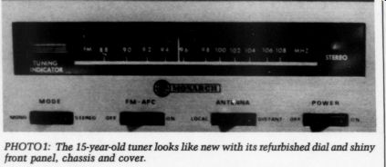
PHOTO1: The 15-year-old tuner looks like new with its refurbished dial and shiny front panel, chassis and cover.
The first step was preserving the remaining dial markings so that my new dial would be compatible with the tuner's front-end alignment circuits and pointer. I used a piece of black paper to create the proper background, then photocopied the original dial. The result is shown in Fig. 1. Note that all four edges of the glass are visible in the copy, along with the partially obliterated numerals. I then stripped the dial of the remaining numerals, leaving a clean piece of glass.
The next step was devising some method of applying new lettering to the glass. I finally decided that reverse rub-on white lettering would fill the bill.
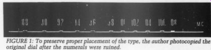
FIGURE 1: To preserve proper placement of the type, the author photocopied the original dial after the numerals were ruined.
Over the next several months, I discovered that a set of reverse rub-ons is a rare beastie that only comes in certain colors and sizes, none of which were suitable for my purpose. I then turned my attention to my junk box, where I found a set of small, white, positive rub on lettering. (DRI-Transfer catalog #AUD-1W manufactured by Russell Industries, 3069 Lawson Blvd., Oceanside, NY 11572. I purchased them several years ago at a local TV repair shop.) I also dug up a piece of very thin glass.
With these materials in hand, I decided to make a glass ‘sandwich,' with the lettering in between.
First I cut the glass to approximately the size of the dial plate, using an inexpensive scoring tool and a Mototool fitted with an abrasive cutting disk.
(Wear protective eye goggles, please.- Ed.)
I then placed the blank dial plate directly over the photocopy of the original dial. I drew in the horizontal number bar by laying down two parallel strips of masking tape spaced about 3mm apart and painting the space be tween with white model-airplane enamel. The timing for removing the masking tape was critical: too soon and the paint would run; too late and the number bar would have ragged edges. I waited until the paint was just beginning to become tacky before removing the tape. The paint was completely dry after 48 hours, and I could letter the rest of the dial.
Once again, I placed the dial plate over the photocopy, with the new number bar parallel to the number bar on the copy. I used uppercase I's from the rub on sheet for the small, vertical station pointer marks, taking great care to line them up with the ones on the original dial. With the vertical marks in place, I added the station numerals and letters.
In an attempt to modernize the unit a bit, I decided to use 'MHZ' instead of the “MC ” on the original dial. I had to guess at the placement of the words “Tuning Indicator ” and “Stereo, ” and both of these wound up being a few millimeters off. The error is so slight, however, that it was not worth redoing.
I placed the thin glass sheet prepared earlier over the dial glass, then placed the “sandwich “ into the dial clips (which had to be sprung open a bit to accommodate the increased dial thick ness). The final result is shown in Photo 1. In this photo, the unit is tuned to station WFLN ( Philadelphia) located at 95.7MHz in the FM band, and the dial pointer is located just about where it should be.
After all this, I returned to the original task of repairing the tuner's electronics.
A dried-out filter cap and an open 12V zener regulator were the cause of the tuner's ailments. Replacing the zener diode with a 7812 regulator and adding some fresh filter caps restored it to a level of sonic performance worthy of its refurbished appearance.
Benjamin L. Poehland; Malvern, PA 19355
EASY VISE ASSEMBLY
You can BUILD a holding vise for circuit boards by following these easy directions. Cut a piece of 0.75-inch plywood (or board) about 12 by 16 inches. In the middle of one end of the board, drill a 0.25-inch hole. At the opposite end, saw a cut the length of the board to within about 3 inches of the drilled hole. The board should look like Fig. 1.
Next, cut two 1-inch-diameter dowels 2 inches long from a piece of broom handle. Drill a 1/8-inch hole 1 inch deep in one end of each dowel. Insert a #8 by 1.75-inch wood screw through the hole in the board and fasten one dowel to it.
Similarly fasten the other dowel some where along the sawn cut in the board.
Cut two 1.5-inch squares from a piece of 1.5-inch plywood (or board). Drill a 3/16-inch hole in the middle of each block and a hole 0.5 inch from the top of each dowel. Glue a wooden clothespin on one edge of each block. With a 3/16-inch by 3-inch machine bolt, fasten the block and pin to the dowel. The left dowel and pin are shown in Fig. 2.
The clamp, or vise, is now complete. You can spread the pins apart, swing them open or angle them up or down for any size circuit board and any working position. If the screws are tight, the vise will hold the board firmly enough for hand drilling.
WILLARD L. RAMSAY; Newcastle, NB E1V 3P1, Canada
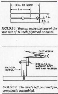
Fig. 1; FIGURE 2: The vise's left post and pin, completely assembled.
----------------
Also see: A BROADBAND SIGNAL SNIFFER