A GAIN OF TEN AMPLIFIER
I HAVE OCCASIONALLY needed a battery operated amplifier of precise gain to use as a preamplifier for my distortion analyzer, or as an output amplifier for a low output signal generator.
Figure 1 is a low distortion amplifier schematic with a gain accuracy limited only by the precision of the resistors used in the feedback loop.
Before describing the circuit, let's briefly review general op amp operating Principles. The two most important characteristics of ideal op amps are:
Principle 1. Both inputs have an in finite input impedance; no current can flow into or out of an input terminal.
Principle 2. The negative feedback applied to the inverting input acts to keep the voltage at the inverting in put the same as the voltage at the non-inverting input; both input terminals are always at the same voltage.
Of course, real op amps do not have infinite input impedance, but the above statements are sufficiently accurate at audio frequencies that they provide a basis for op amp design.
The simplest form of an amplifier circuit is the inverting configuration (Fig. 2). If 2 volts (2V) (AC or DC) are applied to the input, 0.002A (2mA) flow in the 1 k-ohm resistor because the op amp end of the resistor is at ground potential (Principle 2 above).
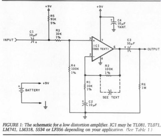
FIGURE 1: The schematic for a low distortion amplifier. IC1 may be TL081,
TLO71, LM741, LM318, 5534 or LF356 depending on your application. (See
Table 1.)
This current cannot flow into the inverting input (Principle 1) so it must flow through the 5k resistor into the output of the op amp.
From Ohm's law, if I=0.002, and R = 5k ohm, the voltage across the resistor must be 10V. Since the input end of the resistor is at ground potential, the output end must be at -10V.
The voltage gain of an inverting amplifier, then is -R2/R1: in this case
-5k/1k or -5.
Note that the input impedance is 1 k-ohm in this configuration (2V/2mA).
If 2V are applied to the non-inverting input (Fig. 3), the inverting terminal is also forced to 2V (Principle 2). Once again 2mA flows through R1 and R2, only this time in the opposite direction (note: this time R1's op amp end is positive with respect to the other end).
Again a 10V potential difference must exist across R2 for this current to flow. However, the inverting terminal end is already at 2V, so the output end must be at 2+ 10=12V. The gain of this circuit is 12/2 or 6.
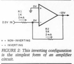
FIGURE 2: This inverting configuration is the simplest form of an amplifier
circuit.
Mathematically it is equal to (R2/R1) +1. This circuit cannot have a gain less than one, whereas the inverting circuit can have any gain value de pending on the resistor ratios. Note also, that the input impedance is in finite since no current can flow into the non-inverting input (Principle 1).
In practice, since no op amp is ideal, an infinite input impedance cannot be achieved.
One other circuit, little used in consumer audio is the differential amplifier (Fig. 4). Imagine first, that the inverting input is at -1V, and the non-inverting input at + 1V, for a dif […]
FIGURE 3.
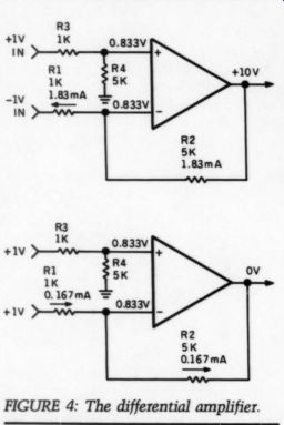
FIGURE 4: The differential amplifier.
From Principle 1, the same current must be flowing in R2 for a voltage drop of 9.167V. Remembering that the inverting terminal end of this resistor is at 0.833V, the output voltage must be 0.833 + 9.167 = 10V.
So this circuit has a gain of 5 for differential signals.
How about common mode signals? Apply 1V to both inputs. The non inverting terminal of the op amp is still at 0.833V; so is the inverting terminal. 0.167mA is now flowing in R1. (Can you see why?) This same current is flowing in R2, so the voltage across it must be 0.833V.
The inverting terminal end of this resistor is at 0.833V and the current must flow toward the output, so the output must be at 0.833-0.833= 0.0V. In other words, voltages appearing at both inputs do not appear at the output. This arrangement is often used in professional equipment to suppress 60Hz in low level inputs, for example.
Since I wanted a rather high input impedance, and did not want phase reversal in my circuit, the non inverting mode seemed indicated.
However, for a gain of 10, I needed the ratio of R1 and R2 to be precisely 9:1. This ratio is not easily achieved using readily available one percent resistors.
I used another approach borrowed from differential amplifier topology, with the inverting input to the circuit grounded through C2. Using the usual method of analysis, I applied 1V (AC, so one end of R1 is essentially grounded) to the input of the circuit.
The voltage at the non-inverting terminal will be 0.91V. The current flowing through R1 (0.0909mA) will also flow through R2 for a voltage drop of 9.09V across R2. When added to the voltage appearing at the inverting terminal end of this resistor, the output must be at 10V for an exact gain of 10.
R5 biases the input to approximately half of the battery voltage, and C2 sets the DC gain at one so the out put is also normally at half the battery voltage. If we replace C2 with a jumper, the circuit would try to amplify the approximately 4.5V on the input of the op amp. Since the gain is 10, and the op amp cannot generate 45V, the output would be pinned at the positive rail. With the gain rolled off to one at DC by C2, the output patiently sits at 4.5V, just like the input.
The circuit is intended for 9V battery operation. However, it can be used with any voltage up to 36V. It can also be used with dual supplies up to +18V by:
-- deleting the jumper to pin 4, and connecting the negative supply directly to pin 4.
-- deleting R5, since bias to half the positive supply is no longer needed.
-- soldering a 0.1uF ceramic capacitor from pin 4 to ground for bypassing purposes.
The circuit can be used as a differential amplifier by unhooking the ground end of C2 and connecting the second input to it. Common mode rejection can be ''tweaked'' by changing the value of R2 by less than 0.1 percent. You can experiment with different gains by simply following the rules outlined above. Remember, R3 must match R1 and R2 must match R4. Gains of greater than 100 are generally best achieved by cascading two amplifier sections.
Several different op amps can be plugged into the circuit interchange ably. Table 1 lists the performance differences when certain op amps are used. The TL071/81 is the best choice for all around performance.
The 5534 is best for low noise, low distortion and low impedance circuits at the expense of increased current drain. It is not usually stable at gains of less than three.
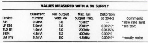
TABLE 1---VALUES MEASURED WITH A 9V SUPPLY
Quiescent current
0.5mA 3.9mA 1.9mA 45mA 5.4mA
Full output volts PP 6.0 50 6.0 6.2 6.0
Max. full output freq.; Distortion at 20kHz; 15kHz -- pp 0.075%"
0.0135%
0.005%
0.009%* *mostly noise
Comments
*slew rate limit
*see text
The 318 is the speed and band width champion, In fact, it may oscillate at several megahertz unless R2 is bypassed by 4 or 5pF. The 356 behaved in a very strange fashion.
The negative peak seemed always to be clipped. Most op amps go into clipping abruptly; however, the 356 negative peak did so gradually, requiring that the peak-to-peak output be reduced below 3V before the severe clipping could be eliminated.
The high 20kHz distortion with this op amp is due almost entirely to this phenomenon. Several samples acted this same way. If exceptionally low current consumption 1s needed, and poor high frequency performance can be tolerated, the venerable 741 is still a good choice.
ABOUT THE AUTHOR
Author Muller has been an audio enthusiast since he scratch-built his first 15W tube amplifier in 1955. Since then his audio system has had a few design and construction changes [...] equipment, some of which has appeared in the pages of TAA. He is also a founding member of the Southeastern Michigan Woofer and Tweeter Marching Society audio club, a director of the ABX Company and a member of the ty. Professionally, the author is a physician specializing in lung diseases and teaching at the local medical school.
--------------------
Cross Switch
Below is a photograph of a cross-stitch I designed and my wife made. It is about 14 inches wide and 5 inches high. What better way to remember the formula for ohm’s Law.
Jack Philpot; South Holland, IL 60473
by Bernhard F. Muller
----------------
Also see: VACUUM TUBE FUNDAMENTALS by Robert Mcintyre