VACUUM TUBE FUNDAMENTALS
FULL GENERATION has since the heyday of the vacuum tube.
The society that thought “a transistor” was for listening to the ball game has vanished. Transistors have gradually replaced the vacuum tube, set ting new standards of performance and economy in almost every application--except high accuracy audio.
Only in this limited area has interest in the vacuum tube been revived
[Many guitar players also still prefer tubed power amplifiers.-Ed.].
One consequence of the vacuum tube's decline has been the growing lack of familiarity with even its basic principles. The purpose of this article is to outline these basic proper ties. The many vacuum tube applications tube will be discussed in forth coming articles.
Diodes
The simplest vacuum tube consists of a heated structure, the cathode, capable of emitting a large cloud of electrons called the space charge.
These electrons are attracted or repelled by a metal anode, or plate in American usage. When none of the space charge reaches the plate, the tube is cut off (Fig. 1, Point A).
Coming out of the cutoff, the tube produces the familiar diode “knee. ” As the voltage rises, the current in creases more linearly until it eventually levels off when all free electrons reach the plate. This condition, called saturation (Fig. 1, Region B), is never completely reached in practice, which is a fundamental property that distinguishes vacuum tubes from transistors.
Now let us re-examine this curve from a different angle. Applying Ohm's law to any position on the curve will yield the DC plate resistance of the tube at that point (Fig. 1, at C for example). A similar application of Watt's law gives the plate dissipation for that condition. All the power lost in the DC plate resistance must be radiated as heat from its surface.
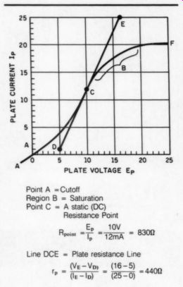
FIGURE 1: The plate curve of a fictitious diode. All possible operating
conditions will fall somewhere on Line ACE.
Another name for this resistance is the static plate curve. Where the curve is straight, the current follows the voltage linearly and the tube acts like a resistor. Its value may be deter mined from the static curve by finding the difference in current for a small change in voltage, then applying Ohm's law to the results.
The computation yields the AC plate resistance, typically about half the DC value. It is drawn as a line tangent to the curve at the point of interest; its magnitude determines the slope of the line. The plate resistance near point C of Fig. 1 was calculated from points D and E of Line DCE, although any two convenient points on the curve could have been used.
The term ‘plate resistance' is usually reserved for the AC value.
The coordinates at the static point are normally solved for power, not resistance, as the static plate dissipation is of far greater interest than the actual value of DC resistance.
Triodes The conductivity of a diode can be modified by either magnetic or electrostatic means. If we place a wire control grid in the electron stream, the conductivity of the diode will depend on the electrostatic potentials of both the plate and the grid. If the grid voltage is changed in steps, each voltage the grid assumes will create its own unique static plate curve. An ordered collection of static curves is called the static plate family (Fig. 2).
Although plate and grid voltages both determine plate current, the grid will have far more effect since it is closer to the cathode. Also, so long as the grid is kept below cathode potential, it cannot itself conduct cur rent. Because little or no power is required to hold the grid at any desired negative level, tubes are designed to be operated with their conductivity reduced by bias. Zero bias, not saturation, usually limits the highest level of conductivity. The use of bias to reduce, not increase, conductivity is the second fundamental distinction between tubes and transistors. A third important difference is the sensitivity of triodes to the plate voltage variations.
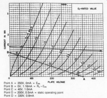
FIGURE 2: The static plate family curves. The negative grid increases
the DC resistance of the tube. It cannot affect the AC plate resistance
much, so all the curves slope about the same.
The DC Amplifier
If a current sensitive load such as a relay is inserted into the plate circuit, it may be actuated either by increasing the plate voltage (and therefore the current) or by decreasing the bias.
Control of plate current through a change in grid voltage is called transfer conductance, or simply transconductance. By the way, bipolar triodes are called transfer resistors, or transistors for short.
When we compare the effect on the load of a change in plate voltage to a change in grid voltage, the resulting ratio is called the amplification factor, or mu. The mu is a direct measure of grid sensitivity, and typically ranges between about two and 100.
Large values of mu imply the capability of high amplification, high transconductance implies large power gain and high plate resistance in a triode implies the inability to drive low impedance loads.
The AC Amplifier
A tube will amplify AC if a signal is superimposed on the bias. The plate current alternates proportionately, so long as the combination of bias and peak input voltages does not exceed zero or cutoff. Clipping occurs at cutoff, and at positive voltages unless the grid receives enough power to drive through the grid conduction region.
Resistance Coupled Amplifier
Devices such as relays use current fluctuations directly, but most applications require a voltage output signal. The most common conversion method is to place a resistance load in the plate circuit (Fig. 3b). This produces a static voltage drop at the
plate that is compensated for by raising the supply voltage. We now have two plate circuit voltages, supply (Ess or B+) and static plate (E; or Ep).
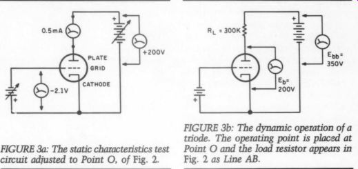
FIGURE 3a: The static characteristics test circuit adjusted to Point O,
of Fig. 2. FIGURE 3b: The dynamic operation of a triode. The operating
point is placed at Point O and the load resistor appears in Fig. 2 as Line
AB.
Amplification takes place in a manner similar to transistor circuits.
Circuit performance depends upon both the tube and the load resistance.
In order to see the effect of the load on the tube, we construct a static load line (Fig. 2, Line AB). Recall from the discussion of diodes that a resistance is represented by a sloping line. The load line is drawn by assuming two limit conditions.
When the tube is completely cut off, no voltage drop can occur across the load because no current flows.
The plate voltage will equal the sup ply voltage (Point A). Assuming the tube can be completely saturated, its plate resistance will drop to zero leaving the load as the only resistance.
The current through this resistance becomes Point B. The resulting line represents all intermediate conditions, and gives unexpected insights into the circuit performance.
Let's briefly analyze the circuit of Fig. 3b, whose load line AB has been drawn in Fig. 2. Select a static operating point halfway between zero and cutoff. We can read directly from the graph that at a plate voltage of 200, the current will be exactly one half milliampere. A grid bias of -2.1V is necessary to set the point (Point O). Sliding along the line, we mark off the extremes of a 2.1V swing, zero and -4.2 (Points C and D). Projecting downward, we obtain the peak output swing, 40V and 330V, which is about 69 times the input.
We now know the gain and, if we want to measure it, the peak-to-peak current swing. We also see what is wrong with the circuit. Compare the output swing between -3.5 and -4.0 with the same swing at 0.0V; it is less than a third as great. The tube is obviously becoming quite nonlinear as it turns off. The positive going output will be compressed.
This creates second-order distortion.
Nearly all distortion in triodes is either second- or third-order.
Now consider load line E. The grid lines are wide and evenly spaced indicating maximum gain and linearity, but notice what happens to the current swing and the supply voltage.
Circuit performance improves for triodes as load resistance and supply voltage increase, but eventually the supply voltage becomes impractically high.
The absence of significant current swing also means the tube cannot supply current, no matter how small, to any point outside the circuit- hardly a useful condition. In practice, optimum load is no lower than twice the plate resistance for a stage delivering power and no higher than ten times for a voltage amplifier.
Inductance Coupling
Suppose we make the load an impedance (a choke or transformer). Now we have a device with almost no voltage drop, but a load impedance of optimum value. Since the plate operating point is at supply voltage, when the grid swings more negative the plate voltage is going to exceed supply.
The energy for the positive plate swing is provided by the magnetic field of the inductor, so long as the inductance is large for the frequency amplified. Since neither plate voltage nor current are limited by load resistance, the tube may approach its maximum gain, the value predicted by mu.
Bias
Biasing methods for tubes are different from those for transistors. Historically, tubes were powered by batteries identified by letters: A for filament or heater, B for plate and C for grid. These letters are still used, whatever the source of power.
Note that the B and C supplies of Fig. 4 are in series. It makes no difference whether we consider that the grid is biased negative, or the cathode is biased positive. In practice, the cathode is grounded making the en tire grid circuit negative. The bias is fixed by the battery voltage, hence the name fixed bias. The C battery need supply only negligible current.
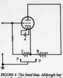
FIGURE 4: The fixed bias. Although batteries B and C are in series, only
B is call ed upon for current. Bias is applied through a grid return resistor
so that C battery does not short input.
Figure 5 shows the second, most common method, called cathode bias. The battery is moved to the cathode circuit, which allows the grid to operate at ground potential. The full plate current passes through the battery. This apparent defect may be remedied by replacing the battery with its equivalent, a voltage drop ping resistor bypassed for AC by a capacitor. This explains its alternate name, self bias, (Fig. 6). The voltage “created” by this resistor must be deducted from the power supply to determine the effective plate supply voltage of the stage.
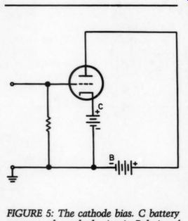
FIGURE 5: The cathode bias. C battery moves
to the cathode circuit. Polarity of the cathode and grid remain the same,
but the supplies are now in parallel opposition. Plate-cathode voltage
is reduced by the C batt.
A unique property of cathode bias is its stabilizing effect. Since cathode voltage depends on plate current, if that current decreases because of age or other factors, the bias is reduced proportionately. Since the bias has decreased, plate current must in crease. The bias circuit is an internal feedback loop, effective for AC as well if the bypass capacitor is removed.
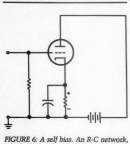
FIGURE 6: A self bias. An R-C network, which also produces a voltage drop,
can substitute for the battery.
The final form of bias useful in audio is contact potential bias, which uses forces within the tube to generate a negative grid voltage. Figure 7 shows the circuit.
Although no source of bias appears in the circuit, in reality a small cur rent loop exists between grid and cathode. Part of this current occurs because electrons that occasionally strike the grid must return to the cathode through the resistor. The other component is the thermoelectric effect created by the hot cathode and cold grid.
The grid resistor is the load for both of these effects, and because the current is quite small it must have a very high value. Even so, no more than a volt or so may be generated. This effectively limits the circuit to high mu tubes and low signal voltages.
Tube Constants
The quantities we designate as transconductance, plate resistance and mu are given the group name tube constants. Of these, the most constant factor by far is the mu. (The term amplification factor has been avoided to prevent its confusion with stage gain, which the mu only partially determines.) The mu is set at the time of design by the porosity of the grid mesh and its spacing from the plate, so theoretically it cannot change. Unfortunately it is impossible to make the grid mesh perfectly uniform, so practical tubes show gain roll-off at low current.
All three constants are derived from the same static factors: grid voltage, plate voltage and plate cur rent. They can be simply and linearly related by:
mu = transconductance
x plate resistance.
Since mu is relatively constant for each tube type, the other two quantities must be inverses, so doubling one halves the other.
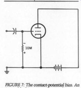
FIGURE 7: The contact-potential bias. An input blocking capacitor is always
required since the grid is negative.
Characteristics of Triodes
Triodes are the simplest tube amplifiers. Fundamentally, they are low impedance devices derived from diodes. They produce little noise and moderate amounts of predominantly second-order distortion. Their principal disadvantages are limited gain, low bandwidth and poor power sensitivity.
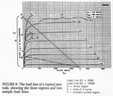
FIGURE 8: The load line of a typical pentode, showing the three regions
and two sample load lines.
Bandwidth
Suppose a positive potential is applied to the grid of an inoperative tube. The plate will charge through the inter electrode capacitance that must ex ist between these two metal structures, and it will assume a slightly negative charge. If the tube is now activated, the amplification of the cir cuit will also shift the plate negative.
(I am neglecting the static plate voltage for the moment.) If the stage has a working gain of 30, the change in plate voltage will be 30 times that of the grid.
Since this voltage shift appears across the grid-plate capacitance, this capacitor must charge 30 times more than it did when the tube was turned off. Thus, the capacitance looks 30 times bigger than it actually is. The multiplication of capacitance by the actual stage gain is called the Miller effect. It is present only between the plate and grid, and is usually the dominant interelectrode capacitance.
This capacitance interconnects the input and output circuits, but be cause the grid circuit impedance is usually higher it acts as a shunt mainly on the input. If the grid circuit impedance is relatively low, it is the plate that is shunted. High frequency response is thus determined primarily by the source impedance, the output impedance and the stage gain.
Power Sensitivity and Gain
The practical limit for accurate amplification with triodes is about 15W.
This is not due to limitations in hard ware but because it becomes impractical to drive them.
A good power amplifier should have high transconductance to control large currents, and low plate resistance to reduce internal losses.
Since these quantities are inversely related, they can only be combined in a tube having mediocre mu. Consequently, no high power audio triode exists; the medium power units tend to have a mu of around 4. Thus, it takes about 40V RMS (root mean square) at the grid to deliver 10V RMS to the speaker.
Voltage amplification meets a similar impasse. The most important constant in a voltage amplifier is the mu, which can be increased only by making the grid more dense or moving the plate farther away. Both of these actions increase plate resistance, which tends to reduce gain.
The best possible compromise yields a mu of about 100.
Evolution of the Tetrode
Suppose the plate of a triode was replaced by a second grid, and the plate moved outward. A positive charge must be placed on this grid to provide enough energy to the electrons so they can reach the plate.
Because the potential of this grid is held constant, it interrupts the fluctuating field of the plate. Thus, it is called the screen grid.
Figure 8 shows how radically the operation of the tube has been transformed. When the plate voltage is zero, the control and positively charged screen grids form a miniature triode. As the plate voltage increases, it begins to steal electrons the gaps in the screen. Further volt age increases divert more electrons, until the process levels off with the plate getting between 60 and 90 per cent of the current.
A special note to experimenters: It is extremely dangerous to run this test unless you take care to avoid exceeding the screen dissipation limit.
Failure to observe this precaution will result in a melted screen. If the tube were a triode, raising the plate voltage would then pull more space charge through the control grid, but the screen grid prevents that. The plate is limited to cleaning out the charge in the vicinity of the screen […]
[…]
a tetrode. R again to Fig. 8, the plate curves may be divided into three regions: the vertical ohmic region, the transition or knee, and the horizontal constant current region.
Only the area to the right of the knee is of value.
The curves do not show a fundamental tetrode flaw. When high speed electrons intercept the plate, the impact causes a secondary emission of electrons. This creates no problem in a triode because the plate is the only positive electrode, and the electrons must eventually return to it. If the plate voltage of a tetrode is near or below that of the screen, secondary electrons escape the plate entirely and return to the cathode via the screen circuit. This loss of plate current causes a deep V-shaped notch to occur in the ohmic region, disrupting the normal operation of the tube. For this reason, tetrode receiving tubes are now obsolete.
Pentodes
Secondary emission losses are prevented in the pentode by a third grid, the suppressor grid, inserted be tween the screen and plate (Fig. 9).
This grid is maintained at or near cathode potential, in order to retard the motion of the low-velocity secondaries without disrupting the more energetic primary flow.
The surface of the plate is also usually treated with a substance such as carbon, which resists emission by bombardment. You should under stand that the grids are of successive ly more open construction.
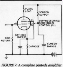
FIGURE 9: A complete pentode amplifier. SCREEN SUPPLY SUPPRESSOR (G3) SCREEN (G2) CONTROL (G1) CATHODE GRID BYPASS RETURN SCREEN BYPASS. The functions of the grids and the external components are labeled. Cathode and screen are coupled through their respective bypass capacitors.
Multi-Grid Tubes
The tetrode (and later, the pentode) was developed to reduce Miller effect. In these tubes, when the screen is AC coupled to the cathode, an electro static shield is formed around the control grid. This reduces grid-plate capacitance of a typical audio pentode to a few hundredths of a picofarad, and extends its frequency range far in to the RF region.
Tube constants are universal descriptions of tube behavior, but al though the relationships apply to pentodes, their application and interpretation are completely different. For example, recall that changing plate voltage has little effect on plate cur rent. This tends to make the concept of mu, fundamental to the operation of triodes, nearly irrelevant. Pentodes do possess a mu of course (it is about 100 times that of a similar triode), but the number is of limited usefulness and rarely specified.
Transconductance measures the effectiveness of the control grid in con trolling current. Since the inner structure of pentodes is basically un changed, the transconductance re mains about the same. The essential difference in pentodes is that the plate circuit is best described in terms of current, not voltage, variation.
Transconductance is the dominant parameter.
Plate resistance is extremely high in a pentode since a large change in plate voltage has almost no effect on current. Put another way, if the mu of a pentode is 100 times higher and if:
mu = transconductance x plate resistance then plate resistance must also be 100 times greater, provided the transconductance is basically unchanged.
The internal structure of the pentode, exclusive of the plate, has a low impedance. This enables the pentode to deliver large amounts of power in to low-impedance loads. Optimum values range between one half and one tenth of plate resistance according to whether maximum voltage or power gain is required. Distortion rises in a pentode as the load impedance approaches the value of the plate resistance.
Pentodes have a bad reputation in high fidelity circles because of their higher distortion, noise and difficulty in handling complex (translation: speaker) loads. They are more properly used where their high gain and efficiency are crucial. For example, the actual available voltage gain of a triode stage ranges between 10 and 75, while a pentode yields between 25 and 500.
The pentode usually has more noise and distortion, but not necessarily more than an equivalent two stage triode amplifier. In addition, the pentode is perfectly content to work into a low impedance load that would seriously disrupt the operation of a triode. A power amplifier designed for triodes will give about twice the out put when equipped with pentodes.
As always, good engineering is the skillful use of compromise. The most critical area is not the design, but the execution.
Beam-Power Tubes
Beam-power tubes function nearly ...
------------
Glossary of Common Terms
AC Plate Resistance. The resistance to a change in the state of conduction calculated by assuming a small change in plate voltage, and dividing it by the resulting change in plate cur rent. (rp, =Aep/Aip) Anode or Plate. The solid metal cylinder designed to be the receptor of the cathode current.
Beam-Confining Electrode. Twin vertical plates at either edge of the electron stream emerging from the grids.
They are held at cathode potential and help organize the beam.
Beam Power Tube. A tube in which the electrons travel in a tightly-organized beam. Principal advantages of this technique are very precise control of charge distribution, and very high efficiency.
Cathode. The structure, usually a heated tube or wire, that is the source of the electron current.
Cathode Bias. A positive voltage ap plied to the control grid by a source otherwise outside the circuit.
Constant Current Family. A family of curves much like the above except that the current is changed in ordered steps and both plate and grid voltages change continuously.
Contact Potential Bias. A negative voltage developed across a load resistor in the grid circuit by forces within the tube.
Cutoff. The condition in which none of the electrons emitted by the cathode reach the plate.
DC Plate Resistance. The opposition of a tube to electron flow, expressed as an equivalent resistance. It is calculated by dividing the plate-cathode voltage by the plate current at a static operating point. (Rp =Ep/Ip) Diode. A tube containing two elements, exclusive of the heater, which allows current to flow in one direction only.
Dynamic Load Line. A line similar to the static line that takes into account changes in the circuit caused by the load.
Fixed Bias. A negative voltage applied to the control grid by a source other wise outside the circuit.
Grid. An electrode permeable by electrons and inserted into the flow in order to inject an electrostatic field at that point. Shapes are usually zig-zag, ladder, round or flattened helix, although mesh or perforated disc are also used.
Grid Transfer Family. An ordered collection of plate current curves created by varying the grid voltage continuously and the plate voltage in steps.
Data are the same as in the plate family, but are expressed in terms of grid, not plate voltage change.
Interelectrode Capacitance. Those capacitances that exist between any two tube elements, even the heater.
Miller Effect. The ability of a tube to amplify its own grid-plate capacitance. The effect exists in any amplifier whose gain exceeds unity.
Pentode. A five-element tube, specifically one including both screen and suppressor grids. (Also hexodes and heptodes: pentode grid converters.)
Plate Dissipation. The power radiated as heat by the plate and acquired from the impact of incoming electrons. It is the product of plate voltage and current at an operating point. (W =Ep x Ip)
Saturation. The condition in which every electron the cathode can emit reaches the plate.
Screen Grid. A subsidiary grid placed between plate and control grid de signed to shield (screen) the grid from the field of the plate.
Secondary Emission. The emission of free electrons from a cold surface caused by bombardment from a primary source. Some devices make use of the effect, although it is usually considered a nuisance.
Space Charge. The cloud of electrons contained between cathode and grid (if any) from which electrode currents are drawn.
Static Load Line. A line drawn across a static family graph by assuming two limited conditions, maximum plate voltage and maximum plate current, and connecting them.
Static Plate Curve. A curve of plate cur rent obtained by continuously in creasing plate voltage, grid and other electrode voltages being held constant.
Static Plate Family. An ordered collection of plate current curves created by varying the plate voltage continuously and the grid voltage in steps, all other electrode voltages being held constant.
Static Point. Any of the conduction conditions to which a tube can be adjusted by means of the plate and/or grid voltages.
Suppressor Grid. A subsidiary grid placed between screen and plate de signed to repel secondary electrons emitted by the plate.
Tetrode. A four-element tube, specifically one employing a screen grid.
Triode. A three element tube, specifically one employing a grid.
Tube Constants. The quantities mu, transconductance and plate resistance, which jointly determine the performance of every tube.
-------------------
... identically to power pentodes. The principal differences are in their construction.
Much of the inefficiency of power tubes is due to the flow of screen cur rent. In addition, the knee portion of pentode curves is quite gradual be cause the suppressor tends to over compensate when the plate voltage is low.
Beam-power tubes place the wires of the control and screen grids in the same plane. Electrons that diverge to pass by the control grid, cannot curve inward again sharply enough to intersect the screen. The field of the screen is not confined and is effective in accelerating electrons. Beam-confining electrodes are placed parallel to the grid’s support wires to prevent electrons from escaping laterally. The net effect of this arrangement is to force the space charge to travel to the plate as a stack of horizontal stripes.
Most beam-power tubes are tetrodes. The area between screen and plate is permeated by the positive fields of each body. As these fields approach each other they mutually repel until at one point, actually a plane, they cancel.
Electrons leaving the screen grid area are decelerated by its field until after reaching the node, the plate field takes over. Since the electrons reach minimum velocity at the node, they tend to bunch up, creating a wall of negative charge. Not only is a suppressor unnecessary, but the effect is proportional to beam current and therefore the secondary emission.
The resulting tube has very sharp knees, low impedance and a screen grid current about a third that of a pentode.
Summary I have presented here only a generalized description of the functioning of those vacuum tubes most com monly employed in audio. I side stepped or short-circuited many areas out of necessity. In particular, I gave no notice that a tube forms a system with its input and output devices. It is their interactions that will deter mine the performance of the system.
Bibliographical Information may find an unexpected challenge, as nearly all books about vacuum tubes are now out of print. The materials listed below were gr to be available at most public libraries, and the private libraries of technical schools and universities.
When locating them, it is best to start with the author's name, as the titles often change between editions.
Catch words such as “Radio,” “Electronics” or “Transistor” are added or deleted according to the fashion of the day, and occasionally a co-author is added.
Although the references are separated according to difficulty, consider able overlap occurs. I have found two of the books, by authors Rider and Terman, to be unusually user friendly.
The best sources for practical information are the popular magazines published in the 1947-1967 era. Although many have perished, a surprising number of these magazines still exist.
-----------
Glossary of Common Abbreviations
Voltage amplification/gain
See Eo See E.
AC plate signal voltage Fixed plate supply voltage DC plate voltage with no (0) signal Control grid bias Control grid bias for multigrid tubes; also E., and E.; for screen and suppressor bias.
Control grid (input) signal voltage Emax, Emin DC plate voltage excursion, maximum/ minimum gm Transconductance ib AC plate signal current Ivo Plate current with no (0) signal Lea Screen operating current Ix DC cathode current DC plate current excursion Po Power output Ip AC plate resistance m Mu or amplification factor I_max, I_min
Notes: Abbreviations have evolved into a standardized format, where each letter carries at least one meaning. They are constructed according to the following rules:
The first letter refers to the quantity measured or to a specific component.
If the quantity is related to the power supply, the letter is capitalized; if it depends upon signal being present, the letter is lower case. Circuit components are always capitalized.
The second letter generally denotes the pertinent electrode or circuit location.
A third letter may be added to specify the conditions of measurement.
The letters b, c¢ and k are reserved for plate, grid and cathode. Grids are numbered, starting from the cathode.
Deviations occasionally found are the substitution of p (for b), g (c), and Ry (Rs), or g, p and R, for grid, plate and load resistance.
------------------
------------------
SOURCES
Basic Books Crowhurst, Norman H., Understanding Hi Gillie, Angelo C., Principles of Electron Devices, McGraw-Hill.
Grob, Bernard and Kiver, Milton S., Applica tions of Electronics, McGraw-Hill.
Rider, John F., Inside the Vacuum Tube, John Schrader, Robert L., Electronic Communication, McGraw-Hill Advanced Books Arguimbau, Lawrence B., Vacuum-Tube Circuits and Transistors, John Wiley.
Eastman, Austin V., Fundamentals of Vacuum Tubes, McGraw-Hill.
Preisman, Albert, Graphical Constructions for Vacuum-Tube Circuits, McGraw-Hill.
Seely, Samuel, Radio-Electronics, McGraw-Hill.
Terman, Frederick, E., Electronic and Radio Engineering, McGraw-Hill Related Readings Crowhurst, Norman H., “What is a Load Line? ” Radio-Electronics, June 1955, pp. 35-37.
--- “More About Load Lines, ” Radio Electronics, April 1956, pp. 39-42.
-- Plotting Tube Characteristics, ” Radio and a News, October 1955, pp.
--- “Making Use of Load Lines, ” Radio and Television News, November 1955, pp. 190-193
---‘What is the Optimum Load?' Radio Electronics, March 1954, pp. 38-39.
Ravenswood, Herbert, “Tube Data and Amplifier Design, ” Part 1, Radio-Electronics, November 1957, pp. 47-49.
--- “Tube Data and Amplifier Design, ” Part II, Radio-Electronics, December 1957, pp. 56-57.
Reference Source Tremaine, Howard M., Audio Cyclopedia, Howard W. Sams, 1973.
The following firms have published either condensed characteristics or extended data on vacuum tubes: American Radio Relay League, Amperex (USA), Brimar (England), General Electric (USA), GEC Genelex (British G.E.), Mullard (England), N.V. Philips (Netherlands), RCA, Howard W. Sams, Sylvania and Tung-Sol.
---------------
ABOUT THE AUTHOR: Bob McIntyre has been working on his music system for thirty years, and expects to be done any year now. His interest in vacuum tubes revived while looking for a cheap way to fuel a set of Dahlquist loudspeakers. The speakers have long since departed, but his interest in tubes has not. He is a repair technician, an avid oenophile and photographer. Both, alas, as an amateur.
--------------
AD:
LINE GARBAGE
It can penetrate your system's power supplies-even through the power trans formers, diodes and filter capacitors. If you think our air, water and earth are polluted, have a look with an oscilloscope at what is riding in on your power line sometime.
General Electric's V130LA10A Metal Oxide Varistor filters out all line spikes above ap proximately 180V and can handle current up to 10A. Just solder one of these across the 110V primary of each of your power supplies in your computer, and you can be certain that your system will not be polluted or en dangered by line garbage.
----------------------------
by Robert Mcintyre
----------------
Also see: DEPARTMENTS and REGULAR COLUMNS