DEPARTMENTS and REGULAR COLUMNS
- Intro
- EDITORIAL
- A CALL TO ARMS
- AUDIO AIDS, by Jack Philpot, Gary A. Galo and Andy Marino
- KIT REPORT Parametric Equalizer, byGary A. Galo
- CLASSIC CIRCUITRY, The Jefferson 2A3 Amplifier Circuit
- SHOWCASE : A study in Wood, By Norman Townsend; Borbely Integrated Amp, By Stephen Nitikman
- Just Looking
- LETTERS
Intro
With low feedback, low power and a MOSFET class-A topology, K. Lang's 20 watt, compact power amplifier is unique. We welcome another fine device from a German author. Mr. Lang's work first appeared in Elrad, a West German monthly. New “intelligent ” switches do a better job than we can in turning on power to your sensitive audio equipment.
L. B. Dalzell has built a whole range of power controllers to prove this point and he discusses them cogently and informatively, starting here.
When you are trying to manipulate a tiny signal, or measure it, it is often too small to work with comfortably or to measure accurately. B. Muller decided that a precise 10X amplifier could be useful in such situations, so he designed one and tells us, with some nice tutorial instruction and good data on opamp performance, how to build one for ourselves.
Bob Mcintyre believes it is time to introduce those who grew up on an exclusive diet of transistors and integrated circuits to the pleasures of tube technology, which until recently looked like a dying discipline. His first article in a series begins here.
In the shortcut/upgrade department (Audio Aids) we have G. Galo, Jack Philpot and Andy Marino giving us excellent morsels (see below). Gary also reviews a vintage parametric equalizer in Kit Reports, see below. The publisher offers a $25 prize to any reader who provides a reproducible b&w photo of our Classic Circuitry amplifier, below.
Next time watch for a tube type, direct coupled headphone amplifier and some special surprises for compact disk enthusiasts.
Editorial--A Call to Arms
We get a few letters which are especially gratifying to us of which this one is fairly typical. I quote in part:
The [ TAA] feature that impresses me most is the level of reader involvement. It is a lively, open-minded, and stimulating interaction that shows the proper meaning of the word “amateur. ” Unlike the majority of hi-fi “hobby ” magazines whose content consists of lecturing to the reader about flashy, highly advertised pieces of technological fluff, there is a sanity about TAA that exists virtually nowhere else in audio. Instead of telling your audience what to do as if they were only computers to be programmed, you welcome their participation.
I have become a convert, obviously, and have been promoting TAA tirelessly since I discovered it. Recently, while in a local high-end shop, I was noting the various, often conflicting viewpoints that were presented in your magazine, both in articles and letters. The salesman I was talking to quite earnestly asked how the magazine could possibly be any good if it didn't decide for the reader which of the ideas or products were good and which weren't.... I applaud TAA's efforts to create an enlightened, involved public. "Naturally we appreciate such letters because they match exactly what we try very hard to achieve. In a related vein, an author called the other day and said flatly, and more than a little peevishly," I don't understand why anyone would want to write articles for your magazine for the kind of money you offer." I said I didn't understand it either. I explained that we pay what other magazines do, which, considering our circulation, is much more of the subscriber/advertiser dollar than the larger books are offering authors. But I also said I was quite sure most authors were moved to write for other reasons. The satisfaction of sharing one's creative efforts is a primary one, I'm sure. Another is the battle we all wage with mortality. Sharing something of worth on a printed page is one small way of putting something of our own unique selves into time and space where it may survive us.
But the primary motive is the satisfaction of sharing and being appreciated. Believe me when I say that an editor's or a publisher's satisfactions are very nearly the same. [ am awed by what our authors produce. And their work, shared for a very small monetary return, is the vital center of what makes this magazine the personal, satisfying and exciting vehicle it is.
What appears in these pages is, by any yardstick, excellent information, the result of the imaginative hard work authors do to share it with you.
The staff's role in this enterprise is based on their commitment to the best professional work possible, given our very limited resources and size. And they do a wonderful job-far beyond the ordinary, humdrum standards of many publication staffs.
Ten years ago when we moved from Swarthmore, Pennsylvania to Peterborough, New Hampshire we did not own one machine, other than two typewriters, a little hand operated waxer and an ancient addressing machine we soon abandoned.
Today, by careful husbanding of your subscription money, we do all our circulation fulfillment, fast reply card processing, text processing and graphics work. We are able to send finished negatives to our printer. This means that your subscription money and the ad revenues do more work for you than almost any magazine you subscribe to. We are proud of that.
Our motive in building our publishing capability is the same as your own in subscribing: love of good sound and pleasure in it. Which is what motivates authors as well.
It is also the motive of our hardworking contributing editors who also spend much time and effort answering your letters or reviewing manuscripts.
Considering all that, is there something you could be contributing beside your subscription money? Audio is a rewarding, high-tech avocation. It is not a mere hobby. It is a fine, enriching form of relaxation and excitement for the intelligent, self-confident man or woman who wants to understand what is going on be hind the equipment's faceplate. TAA's readers are not a breed of timid dabblers or tinkerers. They do their homework, plan systematically, select their hardware prudently, support good vendors enthusiastically and habitually, and build gear that performs at the best possible level they can afford and/or achieve. Audio Amateur is no resource for audio-freaks who merely want a cheap, quick shortcut to equipment they cannot afford to buy already assembled. Building, for the true audio amateur is a positive pleasure, not drudgery to be endured to get the goodies.
The entry fee for this craft is a lot of study, experimentation, mistakes and experience. But its rewards, both during building and in the countless hours of listening, are rarely matched in other avocations.
I hope you believe such satisfactions are worth telling others about, worth some missionary effort. And that the growth of the number of people like yourself who have discovered audio technology's satisfactions can enhance the avocation for you.
At present audio amateurs in the US constitute a very small 'market' for tools and hardware. If those markets in England, Denmark, West Germany, France and Japan were comparably small percentages of their national populations, I would have very little to argue about. But this is not the case. Japan's 120 million population includes a group of audiophiles who support two audio construction magazines whose circulations each exceed 35,000 copies monthly averaging 240 pages per issue.
Denmark's High Fidelity magazine has a monthly circulation of over 40,000 giving a large portion of its editorial space to construction articles-in a Danish speaking country of five million. Comparable interest levels exist in Great Britain and West Germany. It is true to a far lesser extent in France, but even there a renaissance of loudspeaker construction and manufacture is underway and directly traceable to articles in L Audiophile magazine.
Some will tell me that value-added taxes in these countries has a strong effect on do-it-yourself endeavors.
Doubtless true. Kits of parts for most devices are free of tax where the finished goods are subject to tax. But the differential is too great to be explained by that one factor. In this country of over 300 million, Audio Amateur enjoys an average annual circulation of just over 6,000. Stereophile and The Absolute Sound are both moving up toward 30,000 while Audio, at last report, was holding steady at about 140,000 per month.
As a corollary to do-it-yourself in those countries, the kit electronics and parts vending businesses are very healthy and active. The only do-it yourself businesses that seem to thrive in the USA are for the antiquated handcrafts: every town over 5,000 population seems to have a thriving ceramics store.
We could be doing a lot more with this magazine if every audio amateur was aware that one of our most pressing needs is convenient and quality sources of supply. Those vendors who use this publication to tell you about themselves are generally small, imaginative, and not too unlike your self in their enthusiasm for the best sound possible. Their offerings are worth your time and effort to find out about them. Don't worry too much about making the magazine fat and rich, or making millionaires out of the advertisers.
Those sources will flourish and get better at supplying the kind of goods and services they can offer as the audio amateur community responds to them. A clear and related example exists in the younger sibling of this magazine, Speaker Builder. A string of struggling, innovative small vendors have set up shop selling loud speaker parts across the USA and they are flourishing at least partly because the readers of SB are responding to their offerings. We try to make it easy for readers to do this. But it is discouraging to me as publisher to have two or three letters a week from readers asking where they can find a product-when it is advertised in the current issue.
It is time, I believe, for a call to action to every one of us who cares about good sound and the delights of audio construction. The first installment of a new feature on sources of supply, whether advertiser or not, will appear next time. Many of you have made suggestions for that listing in your letters. I welcome more of these from you. Let's get moving on a new birth of satisfying, and sparkling new audio construction. Next time you will be seeing some splendid work from readers overseas who can not only find boxes for their construction, they can anodize and en grave faceplates for their equipment, themselves.
If you have done work you are proud to share, send good clear photos of it to me, preferably in black and white, and we will showcase it.
This craft deserves our best and its satisfactions are unmatched. I hope to see evidence of a rejuvenation of it here in our homeland, and soon.
You are, as my reader friend quoted above, points out, a lively and involved group. But in this matter of our supply infrastructure, we have a lot of work to do. I welcome your action, and your show and tell.
-E.T.D.
Just Looking
Analog Devices introduces two hybrid digital-to-analog converters (DAC), the 4-bit HDG-0407 and the 8-bit HDG-0807. They claim to increase flexibility by operating with a single +5V power supply and they are compatible with TTL (transistor-transistor logic) signals.
They feature high update rates of 50MHz, maximum settling times of 12nsec and 18nsec for the HDG-0407 and HDG-0807, respectively.
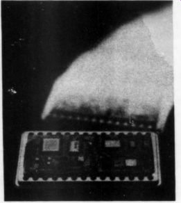
These pin compatible additions to the HDG video DAC series feature complete composite controls, including self-contained, digitally-controlled sync and blanking, reference white and 10 percent bright capability. In addition to their raster scan graphic systems, the devices may also be applied in analytical instrumentation, TV video reconstruction, color graphics, ECM (electronic counter measures), process control, digital special effects and CAD/CAM.
Also introduced is a complete single channel, 12-bit integrated circuit data acquisition system (DAS). The AD369 is said to be the only device to combine a programmable gain instrumentation amplifier (PGIA), a track-and-hold (T/H) amplifier and a 12-bit ADC all in a small 28-pin metal hermetic package. The AD369's makers claim it's the only software-controlled programmable-gain hybrid DAS in the industry.
For further information contact Analog Devices Literature Center, 70 Shawmut Rd., Canton, MA 02021.
B.E.L-tronics Limited's satellite television receiver features Micro Eye block downconversion circuitry and is compatible with both C and Ku band transmissions. The receiver is a quartz synthesized digital PLL (phase lock loop) model with three-channel memory, and provides matrix or discrete stereo. Other features of the new receiver include wide and narrow bandwidth selection, polarizer control, built-in RF modulator, digital readout of signal strength and audio subcarrier frequency, and up/ down scan buttons. Its ceramic resonator is said to assure consistent stability of the local oscillator and the final picture.
For more information contact B.E.L-tronics Limited, 2422 Dunwin Dr., Mississauga, Ontario, Canada, L5L 1J9.
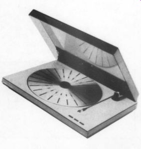
Bang & Olufsen introduces a moderately priced straight arm and turntable unit that they claim offers improved tracking, even for warped records. The B&O RX2 features their slim-line styling, a newly-developed tonearm which is said to minimize resonance and record wear and a heavy pendulum suspended chassis to protect against external vibrations.
For more information contact Bang & Olufsen of America, Inc., 1150 Feehanville Dr., Mount Prospect, IL 60056.
The latest Audio Kits catalog from Marchand Electronics includes:
The XM1 Electronic Crossover Net work, a fourth-order state-variable filter design, providing both low- and high pass outputs with a 24dB/octave slope.
Marchand's PM2 50W power amplifier module is said to deliver a clean, low distortion 50W of power, and is rated to drive reactive loads with a full output phase angle of up to 45 degrees. The circuit uses an integrated driver chip and two complementary Darlington power transistors. The module is protected with an output current limiter and a temperature sensor.
The XP3 three-way amplifier is an in amplifier package on one circuit board, with a three-way, third-order Butter worth crossover to split the audio spectrum into low, mid and high frequency bands. Each band has a power amplifier for directly driving the woofer, midrange and tweeter. It is all mounted on a 5.5 by 6.5-inch board.
Marchand kits are available as bare boards, complete kits or preassembled.
Prices vary. For further information and a copy of the catalog write, Marchand Electronics Inc., 1334 Robin Hood Lane, Webster, NY 14580.
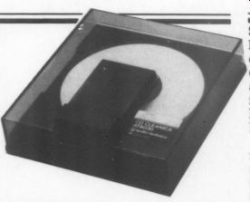
Audio-Technica's new compact disk cleaning and maintenance system, the AT6030 CD Cleanica is designed to keep CDs in good playing condition to prevent damage to the delicate surfaces.
The soiled disk is placed label side down on the system's turntable, the dust cover is closed and a slide lever on top is moved back and forth. The motion is repeated until the disk makes a complete revolution. As it revolves it makes gentle contact with a soft, specially-constructed cleaning pad. The cleaning strokes are radial, rather than circumferential. A special cleaning pad and fluid are included for careful hand cleaning of obstinate dirt and spots.
For more information contact Audio Technica U.S., Inc., 1221 Commerce Dr., Stow, OH 44224.
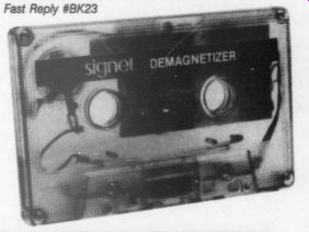
Signet's SK308 Audio Cassette Demagnetizer is powered by a 1.5V mercury disk dry cell. The unit's electronic circuit generates a large electronic field at the tape head, then slowly breaks the field down. As the field decays, tape head magnetism is said to dissipate in less than one-third of a second.
Signet’s SK302 contact cleaner/ restorer includes three items: a bottle of special liquid cleaner to dissolve corrosion, oils and dirt, a supply of double ended cotton swabs for cleaning non standard contacts and an assortment of porous plastic probes shaped to fit into or over a terminal device to convey fluid internally and externally.
For further information contact Sig net, 4701 Hudson Dr., Stow, OH 44224.
Revox introduces their universal infrared transceiver system that offers operating flexibility in different rooms for most infrared remote-controlled audio or video components. The system can be used with most wireless infrared remote-controlled audio, video or satellite receiver units. All you need to operate throughout your home are speakers and a transceiver in each room.
The heart of the unit is a cigarette pack-size infrared transceiver wired to a tiny “repeater ” unit. The transceiver converts the infrared signals to electrical impulses driving a pair of infrared LEDs contained in the repeater unit. The transceiver can be adjusted to function as a full transceiver or simply as a 'receiver.' With the 38-button remote control you can switch music sources from any room.
For further information write Revox Division, Studer Revox America Inc., Dept TAA, 1425 Elm Hill Pike, Nashville, TN 37210.
Three new Tandberg components make a complete system: the TPA-3016A power amplifier, the TCA-3018A pre amp and the TCP-3015A compact disk player. The TPA-3016A amplifier is a dual-mono design with electrically in dependent channels for perfect channel isolation. Instead of integrated circuits and standard parts, the amplifier uses discrete circuitry with polypropylene capacitors and metal film resistors. Its THD is said to be not more than 0.5 percent.
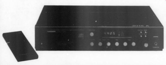
The TCA-3018A preamp uses the same discrete circuitry as the power amplifier and has special features including high-level 20V inputs, with less than 0.009 percent THD, separate four position record and program switches, bi-directional dubbing and gold-plated input and output jacks. The transient intermodulation distortion is said to be unmeasurable.
The TCP-3015A compact disk player uses dual processors operating at a digital sampling frequency of 176.4kHz, is four times the industry norm. A zero low-phase shift is achieved by over sampling and a combination of digital and analog filtering for superior reproduction of transients, dynamic im pacts and complex waveforms.
All three pieces (just under $5800) are available with optional rosewood or black lucite end pieces. For more information contact Tandberg, Labriola Ct., Armonk, NY 10504.
AUDIO AIDS
METERING THE HAFLER POWER AMPS
A simple meter circuit for the Hafler DH-200 and DH-220 power amps can come in handy in your audio installation. The circuit (Fig. 1, one channel) connects directly to the amplifier's speaker terminals. The meter is a Calrad #60-133 VU (volume unit) meter available from McGee Radio and Electronics ( 1901 McGee St., Kansas City, MO 64108). An SPDT center-off miniature toggle switch (Radio Shack #275 325) selects three different ranges. The 100k trimpot in series with the 122k resistor provides a 100W indication at zero VU. Paralleling an 82k or a 16k resistor with the above gives a 10W or a 1W indication, respectively. Resistors are 0.5 W, 5 percent metal or carbon film.
VU meter polarity is not important.
Calrad also manufactures an illumination kit (#60-149) consisting of two miniature lamps for each meter. Operating voltage is 12V, which can be pro vided by installing a small filament transformer (Radio Shack #273-1385) in side the Hafler chassis. The wiring dia gram for the meter lighting is shown in Fig. 2. Be sure the 117V AC connection is made after the amplifier's power switch and line fuse. Also be sure you ground the case of the filament trans former to the power supply ground bus between the two filter capacitors.
Figure 3 shows the meter circuits in stalled inside a Hafler DH-200. Perf-boards facilitate resistor and trimpot mounting, and Molex connectors allow easy removal of the amplifier cover.
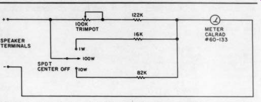
FIGURE 1: This meter circuit for the Hafler DH-200 and DH-220 power
amps connects directly to the amps' speaker terminals.
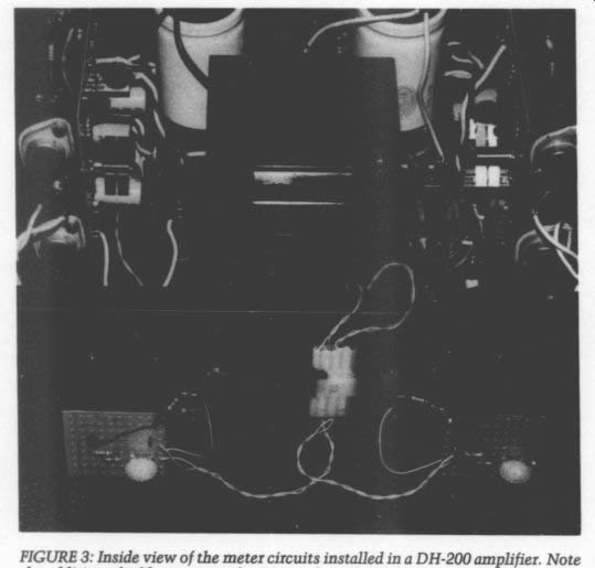
FIGURE 3.
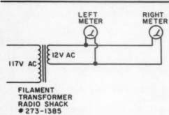
FIGURE 2: Wiring diagram for Calrad meter illumination.
FILAMENT TRANSFORMER RADIO SHACK #273-1385
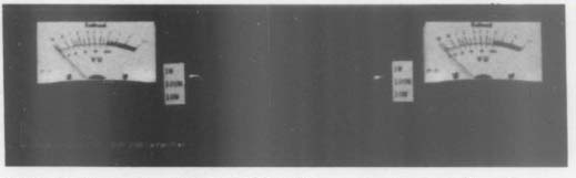
FIGURE 4: Front view of the DH-200 with the meters installed. Note the
range switches mounted next to each meter. (Photograph prepared by Paul
Steinberg.)
Figure 4 is a front view of the DH-200 with the meters and range switches in stalled. You can use a metal hole saw or chassis punch to cut the holes in the amplifier top necessary to accommodate the meters. Be sure you have enough clearance for the meters inside the chassis.
With the meter circuits correctly wired, connect either amplifier channel to a sine-wave generator (set to 1kHz) and an 80, 100W load resistor. Set the meter switch to the 100W (middle) position and adjust the generator's output for 28V RMS at the speaker terminals. Adjust the 100k trimpot for a zero VU indication. Repeat this calibration procedure for the other channel.
You can adapt the meter circuit to virtually any amplifier with any power rating by adjusting the resistor values.
A resistor substitution box is handy for determining the values. If the meters will not fit within the amplifier's chassis, you can mount them in a small project box.
Interpreting VU meter indications is easy. For readings below zero VU, divide the zero VU indication by the number on the meter. In other words, a minus 2 indication on the 100W scale indicates 50W. The only exception to this rule is a minus 1 indication, which always indicates 75 percent of the zero VU reading. For readings above zero VU, you must multiply by the number on the meter. A plus 2 indication on the 10W scale equals 20W.
VU meters are basically average responding devices. If you desire a peak clipping indication as well, you can use VU meters in conjunction with the Old Colony KF-1 clipping indicator.
Gary Garo
Potsdam, NY 13676
CAPACITOR UPGRADE
UPGRADING CAPACITORS is still an effective way of improving an older amp. This type of upgrade is easier now that physically smaller high-quality electrolytics are available. Higher-value caps might be drop-in replacements for many power supply applications. For instance, I was able to upgrade a supply capacitor from a standard-quality 220uF, 63V unit to a high-quality 330 uF, 100V unit with the same physical dimensions.
If increasing a capacitor's value does not seem to be a good idea, you might be able to use a unit of the same value but with a higher voltage. A listing of the highly regarded Panasonic HF Series shows that a 470uF, 16V unit has an impedance of 0.14 ohm at 100kHz, while a 470 uF, 25V unit has an impedance of only 0.072 at the same frequency. Also, if space permits, paralleling two electrolytics to get the required value will yield lower impedance than a single unit of the same value.
These tricks work even better if you use top-quality Panasonic or Nichicon units. Surplus electrolytics pulled from high-frequency switching power supply boards might be a good bet for audio use.
One hint that an electrolytic might be of higher than average quality is a 105-degree temperature rating rather than the usual 85 degrees.
I believe that small-value electrolytics should be dropped altogether in favor of, at least, stacked metallized film types such as those in the Panasonic V Series.
In several tight spots in my power amp, I was able to replace small 1uF, 35V electrolytics with 1uF, 50V V-Series units.
When space permits, you should replace small-value electrolytics with equivalent-value polypropylene, polystyrene or polycarbonate caps.
An excellent place to order Panasonic Z, HF and V Series capacitors is Digi-Key Corporation, PO Box 677, Thief River Falls, MN 57601. Digi-Key's catalog is available by calling (800) 344-4539.
Jack Philpot
S. Holland, IL 60473
LC CARTRIDGE ALIGNMENT
SETTING UP A LINE CONTACT (LC) stylus can be a frustrating and aggravating exercise, mainly because the azimuth and stylus rake angle (SRA) must be perfectly aligned. This is not very easy with pivoted tonearms because adjusting one affects the other. To compound the problem, you are advised to listen for improvements as you make the adjustments. Having only read about the glorious sounds stemming from perfect alignment, it is very difficult to gauge the optimum point.
I had given up on my LC cartridge and settled on an elliptical one until I happened to devise a simple alignment gauge. With it, I was able to align my LC stylus perfectly, as evidenced by the fact that the sound took on a realism I had not expected. I now have a good idea of what those underground reviewers rave about.
The gauge is simply a cardboard cut out, which serves to extend the sensitivity of 'eyeball' azimuth adjustments by a factor of 20 or more. The procedure calls for setting the cartridge parallel to the record surface (to set the SRA approximately), then using the gauge to adjust the azimuth. (The stylus, as viewed from the front, should be perpendicular to the record surface.) You can then “fine-tune” the SRA by varying the tracking force within the specified limits and/or varying the tonearm height + 1/4 inch. The former is preferred because it has a minimal effect on the azimuth and a relatively large effect on the SRA.
To make the gauge, obtain a piece of stiff cardboard. A standard file folder will do nicely. To ensure parallelism, draw two long parallel lines, but use only one segment of each. This segment will be part of edges CS, AB and EF in Fig. 1.
Draw the complete outline on the card board, using the dimensions from your system. Choose a dimension for CD so that the gauge will straddle the cartridge. The length BC (and DE) should allow the gauge to clear the record surface by 1/16 inch at most. The distance between A and F is about 3 inches. Cut out the figure with a sharp razor blade or an X-acto knife. Again, be careful to maintain the parallelism of CD to AB and EF.
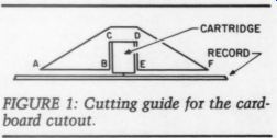
FIGURE 1: Cutting guide for the card board cutout.
To use the gauge, place a good (flat) record on the turntable and set the cartridge halfway to the center. Place the gauge over the cartridge. (Note: Most headshells allow the front of the cartridge to protrude. This is ideal because the gauge can rest on the cartridge itself and establish parallelism directly be tween the cartridge and the record.) View the cartridge from the front and observe for tilt by noting the parallelism between edges AB and EF and the record surface. Shining a light on the cardboard and using the reflected image on the record surface facilitates detection of tilt.
Adjust the headshell or shim the cartridge (the former is preferable because shims degrade the cartridge/headshell interface) until parallelism is obtained.
Do not change the tonearm height to accomplish this, as it is set for SRA.
Double-check the results by turning the gauge around and observing the tilt. If after turning around the gauge) are equal but in opposite directions.
I have checked the validity of using the top surface of the cartridge as a reference by using an optical comparator. On three cartridges, the stylii were perpendicular to the top surfaces.
Unfortunately, the same degree of precision is not carried over to the headshells.
I have checked two tonearms using the gauge and found their azimuth off by at least 2 degrees. No wonder I had such a difficult time setting up my LC cartridge! I hope this simple and inexpensive device will benefit other audiophiles and encourage them to send in their ideas.
We can all use a little help.
ANDY MARINO Chicago, IL 60640
KIT REPORTS
P-94-SR STEREO PARAMETRIC EQUALIZER
Reviewed by Gary A. Galo
THE PHOENIX systems P-94-SR (Fig. 1) is an attractively priced, two-band-per-channel parametric equalizer. Parametric equalizers operate quite differently than graphic equalizers. Graphic equalizers generally have controls at predetermined center frequencies. The center frequencies are not normally adjustable, nor is the width of the area affected. This results in some limitations, as the frequency in need of adjustment is often somewhere between two of the controls provided.
A parametric equalizer, on the other hand, allows selection of continuously variable center frequencies. You may also adjust the width, or Q, of the area affected. Each channel of the P-94-SR has two bands, one covering 40Hz to 960Hz and the other covering 560Hz to 16kHz. You can vary the Q of each band from 0.16 to 2.0 octaves. The amount of boost and cut is + 16dB at 0.16 oc tave, decreasing to + 6dB at 2 octaves.
This intentional reduction of the amount of boost/cut as the Q is widened eliminates any change in overall volume that would otherwise occur.
Phoenix has upgraded the P-94-SR from its original version, the P-94-S, in four significant ways:
1. The power supply has been fully regulated.
2. A hum shield has been added to reduce hum pickup from the power transformer.
3. The 1uF electrolytic coupling capacitors have been increased to 10uF.
4. The maximum boost/cut was reduced from 20 to 16dB. The gain structure was changed to reduce noise and distortion, eliminating four electrolytic capacitors in the process. Figure 2 is the schematic diagram of the upgraded unit.
The P-94-SR is available as a kit ($129) or as a fully assembled unit ($179).
Assembly time for my kit was about 3.5 hours, with a few interruptions. All circuitry is contained on two circuit boards, one for the power supply and one for the equalizer circuitry. This kit should appeal to many TAA readers, as you are required to assemble the circuit boards completely. I enjoy this type of kit more than the “semi-assembled ” type offered by manufacturers such as Hafler.
The assembly manual is clearly writ ten and follows a logical sequence. Also included is an owner's manual that gives a brief introduction to parametric equalizers and instructions on how to use the P-94-SR. The circuitry uses TL-074 BIFET op amps for low noise and fast slew rate. The op amps are supplied with sockets, thus minimizing any chance of damage during installation. Resistors are 5 percent, carbon film types. Polarized electrolytic capacitors are used for coupling, while the supply bypass caps are ceramic disks. I was impressed with the use of polystyrene capacitors in the equalizer feedback circuitry.
My kit was missing the four rubber feet on which the unit rests and did not contain enough ten-conductor ribbon cable.
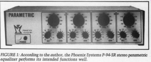
FIGURE 1
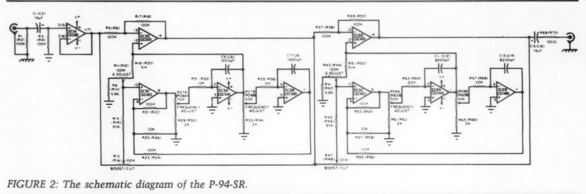
FIGURE 2: The schematic diagram of the P-94-SR.
Bench Tests
In my bench tests, I discovered a high frequency oscillation at the left and right outputs, about 5mV peak to peak, and in the mega-cyle region. I suspected in adequate power supply bypassing, as the board has only two 0.1uF bypass caps for five quad op amps. I added four bypass caps, and the oscillation disappeared.
I wrote to John Roberts, president of Phoenix Systems and designer of the P-94-SR, explaining the problem and what I had done to correct it. He suspected an oscillating negative regulator at first. Before I had a chance to check into this, he called back to report that another unit had been returned to him with the same problem and that additional supply bypassing had solved it. He suspects that the oscillation developed when he modified the unit's gain structure. The reason he did not discover it sooner was probably because not all TL-074 devices exhibit the oscillation and most units are functioning proper ly. Now he is installing two additional ceramic disk bypass caps on all circuit boards included in the kits. I recently built a second P-94-SR (which I am using at work) and found its board supplied with the additional caps. Incidentally, this unit was supplied with enough ten conductor wire, but the rubber feet were still missing.
I must mention that during the resolution of the oscillation problem, I found John Roberts's attitude to be exemplary.
He is truly concerned about the quality of his products and appears eager to do anything he can to resolve problems such as this one.
With the oscillation problem solved, I ran harmonic distortion and noise tests on the unit. I measured distortion with a Heathkit IM-5258 distortion analyzer and a Morrey-modified Heathkit IG-18 signal generator ( TAA 4/75). The residual distortion of the test setup is 0.015 percent. I measured 0.025 percent distortion at 1kHz and 0.028 percent at both 10kHz and 20kHz. At 20Hz, the distortion measured 0.04 percent, but the test equipment residual is 0.03 per cent at this frequency. Both channels measured the same. Although my measurements are higher than the published specifications, the difference between the measurements and the test equipment's residual distortion would indicate that the unit is functioning near or at its published specs. A look at the distortion components on an oscilloscope showed that the measured distortion was dominated by noise. High-order harmonics were not present, which is a good sign.
The unweighted noise level was 75dB below 1V output, exceeding the published specification of -72dBV. Again, both channels were identical. I verified the frequency response as specified, with the gain controls centered properly.
Maximum output level was just over the 8V specified. When driven into hard clipping (10V input), however, the unit produced a pulse-type oscillation rising from each negative waveform peak, as shown in Fig. 3. This oscillation was at full output level, which could be potentially damaging to amplifiers and loudspeakers. On the other hand, it is doubtful that the unit would ever be driven this hard in actual home use.
Frequency calibration was extremely accurate in the center of the control's rotations (320Hz and 3.8kHz for the low and high controls). Above and below these points, calibration was less ac curate. On the low-frequency controls, the 500Hz indication actually represented 650Hz, and a 160Hz indication actually corresponded to 120Hz. On the high-frequency controls, a 6.2kHz indication actually represented 8kHz, and a 2.5kHz indication actually corresponded to 1.8kHz. This was identical for both channels.
Using the P-94-SR
My primary use for the parametric equalizer is in cleaning up noise on non hi-fi material, particularly 78 rpm records. I am now using the P-94-SR in conjunction with the modified McIntosh C-8, described in TAA 1/85. For this purpose, the unit is far more useful than my ten-band graphic equalizer, a modified Dynaco SE-10. I usually found that the noise I wanted to minimize fell somewhere between the controls avail able on the SE-10, particularly in the high-frequency regions. The P-94-SR allows me to zero in on the exact problem very easily. I can also minimize or eliminate low-level hum found on some source material (primarily old broadcast transcriptions).
Most users will wish that the P-94-SR had a bypass switch so that they could instantly compare the equalized signal to the original. I installed such a switch in my unit. The switch wiring is shown in Fig. 4. mounted the switch (a mini DPDT toggle) midway between the left DPDT high-frequency and the right low-frequency controls.
In certain applications, the P-94-SR might be useful connected as a four-band mono unit. In this case, a patch cord would connect the left output to the right input. The left input would then become the mono input, and the right output would become the mono output.
I find it useful to be able to feed the mono output to both channels of the stereo preamp without adding an out board “Y ” adapter. To facilitate this, I added another output jack in parallel with the right output. This is also shown in Fig. 4.
Four-band mono operation can allow you to process up to four different frequencies simultaneously. You may also zero in on the same frequency with two controls, achieving twice as much cut or boost as you can in the normal stereo mode. This is particularly useful for eliminating hum on source material.
Undoubtedly, many readers will be interested in how effective the P-94-SR is at equalizing loudspeaker and room irregularities. The answer is that it is very effective. I have often been frustrated with ten-band graphic equalizers in this capacity. Peaks and dips in need of correction often fall between adjacent controls, making accurate correction impossible. The parametric's ability to zero in on any frequency and adjust the width of the area affected makes it far more useful for this purpose. In many cases, having only two bands per channel will not be sufficient. Therefore, I recommend using two P-94-SRs in the mono mode (described above). Considering the modest cost of this unit, two of them still represent a small investment, less, in fact, than a high-quality ten-band graphic equalizer.
FIGURE 3.
FIGURE 4: Mr. Galo installed a bypass switch in the P-94-SR. He also added an output jack, paralleled with the right output. This is useful for four-band mono operation.
Listening Comments
To evaluate the P-94-SR's sonic cleanliness, I connected the unit to one of my preamp's tape monitor loops. To
check for sonic colorations rather than equalization capability, I carefully centered all the gain controls. The bypass switch described above facilitates “A-B ” comparisons between the equalizer and a “straight-wire bypass.' The P-94-SR is probably the least colored equalizer I have heard. It is not completely free of sonic character, but its imprint on the sound is minimal.
On Lorin Maazel's Rite of Spring (Telarc Digital), the transient impact of the bass was somewhat diminished by the P-94-SR. The bass, in general, seemed to extend slightly lower with the equalizer bypassed. One of my favorite analog recordings to test components is the Wagner Ring conducted by George Solti, on the German Decca pressings.
For this listening evaluation, I selected the introduction to Act II of Die Walkure, sung by Birgit Nilsson and Hans Hotter. Here, the upper string sound lost some of its sweetness when the equalizer was switched in. The mid range, particularly the singers' voices, appeared a bit more forward, and a slight upper bass “warmth ” was added. These two “tonal balance ” characteristics could, perhaps, be solved by carefully re centering the gain controls. This is probably of little consequence because the equalizer will normally be used deliberately to alter tonal balance. The equalizer also compressed transients some what and reduced depth perception.
These are rather subtle characteristics, however, and I consider the unit to be sonically very good. The P-94-SR's noise level is, for all practical purposes, nonexistent. Only by turning my pre amp gain to maximum (without pro gram material, of course) and putting my ear within an inch of my tweeters could I hear any hiss. The equalizer did, however, exhibit a turn-on thump and a short turn-off “squeal. ” Perfectionists could perform several modifications to improve the P-94-SR sonically. In order of decreasing importance, these are as follows:
1. Build a brute-force (outboard) low-impedance power supply such as that used in the Jung-White PAT-5/ WJ1A preamp ( TAA 3/79, p. 24). 1 have used this supply in preamps and electronic crossovers with dramatic results.
2. Replace all the resistors with metal film types.
3. Bypass the electrolytic coupling caps with 0.1F polypropylenes (admittedly a tight fit).
4. Replace the ceramic supply by pass caps with polypropylenes.
Of course, all of the above will more than double the unit's cost. In addition, any modification will void your warranty (one year on parts, three years on specs). I think most users will find the P-94-SR more than satisfactory as is.
John Roberts informs me that he will be updating the P-94-SR in early 1986.
The cabinet and cosmetics will be more attractive, and the new units will have 6000 drive capability, which should appeal to professional users. The equalizer circuitry will remain the same, so the comments expressed in this review should stand. I do wish that John would check the front panel frequency calibration when he designs the new front panel. I would also like to see the hard clipping oscillation problem rectified.
These, again, are relatively minor problems. In spite of them, I still recommend the P-94-SR highly.
Phoenix Systems makes a number of other audio kits. For information about the P-94-SR and other Phoenix products, write to Rhoades National Corp., Dept.
R/P, PO Box 1316, Columbia, TN 38401.
John Roberts replies:
I tried to discourage TAA from reviewing the P-94 because it is a mature product (designed in 1979) with a second generation version already in the planning stage. Mr. Galo has, however, pro vided some valuable feedback, and a good description of the merits of parametric equalization is always worthwhile.
I am most embarrassed by Mr. Galo's discovery of a low-level power supply in stability. I did not previously detect this because it was not present on any of my sample units at the time I made the design upgrade (the original design is un- conditionally stable). It has been corrected and will not happen again As Mr. Galo did not state at what level he made his THD + N measurements, | will presume the noted variance was caused solely by noise. Most distortion analyzers (the Heathkit IM-5258 in chided) simply notch out the fundamental and group noise with the distortion products for measurement, so a wide band circuit with extended frequency response will suffer in comparison to slower or band-limited designs. In this case, I expect that 80 percent or more of the noise that dominated his THD measurement was above 20kHz. For this reason, I prefer using a spectrum analyzer for measuring distortion and assure you that the actual distortion products of the P-94 are well below Mr.
Galo's equipment residuals and the specified --80dB (0.01 percent).
------------------
TECHNICAL QUERY
Write it please: Our phone doesn't do theory
-----------
Specifications
Frequency Range: low band high band Frequency Response Maximum Output Level Distortion: THD + n IM (SMPTE) Noise: unweighted IHF “A ” weighted Q Range Maximum Boost/Cut Power Weight 40Hz to 960Hz 500Hz to 16kHz 3Hz to 100kHz (+0dB, -1dB) unity gain (no inversion) 100 k-ohm 1000 8V (RMS)
0.01 %, 20Hz to 20kHz
0.007 %
-72dBV (1V)
-96dBV
0.16 to 2 octaves
+16dB @ 0.16 octave
+6dB @ 2 octaves 50mA @ +15V 3.3 lbs. (1.5kg)
-----------------
While THD has its limitations as a predictor of sound quality, a useful technique when working with a basic THD analyzer such as the Heathkit is to listen to the product output. That way, it will be fairly easy to distinguish by ear between low-order, high-order and noise-dominated measurements at low to mid audio frequencies.
I am aware of the overload characteristic described by Mr. Galo (in Fig. 3).
Under certain input overdrives, the out put of the TL-074 op amp will reverse.
This full supply pulse (not an oscillation) occurs only in the presence of an already hard-clipped rail-to-rail signal.
Its main potential for damage is that it contains higher-frequency energy than the signal that excited it. As this phenomenon occurs several decibels beyond hard clipping, which itself occurs many decibels beyond when any following amplifier would also hard clip, I do not expect it to cause problems. I will design it out of the next generation product if I can do so without degrading some other parameter.
Regarding frequency accuracy, the potentiometers I use ( Alps) have very tight front-to-back tracking (3dB at -40dB), which is important for stable Q, but only 20 percent absolute resistance tolerance. The next design will use a slightly different topology to reduce its sensitivity to this tolerance. Luckily, most applications of parametric equalization require adjustment by ear, so absolute frequency accuracy is primarily of academic or archival importance.
The major difference between the P-94 and its successor will be cosmetic and feature related. I will probably use the low-Z power supply from my P-100 design (see ‘Preeminent Preamp,' TAA 3/85, p. 16) and crank in a few features that my customers have requested over the years. One final consideration is that the new unit will cost more.
CLASSIC CIRCUITRY
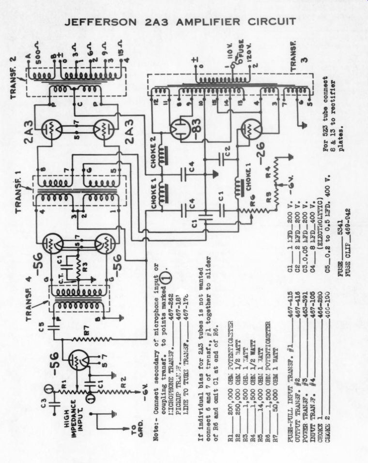
Jefferson 2A3 Amplifier---Date: 1933 Classic Circuitry: Courtesy of Bruce Edgar
SHOWCASE
BORBELY INTEGRATED AMP
by Stephen Nitikman
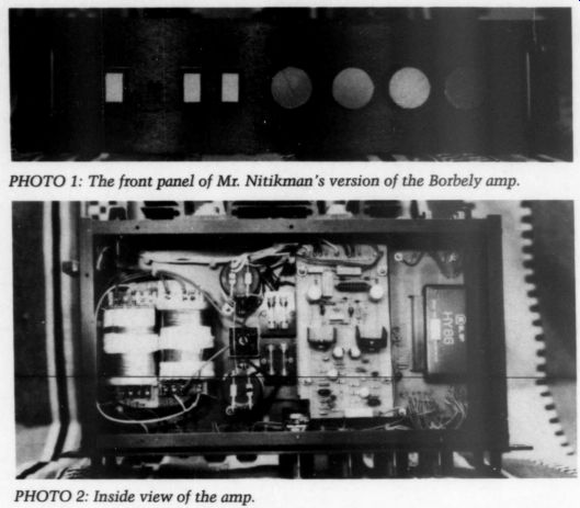
PHOTO 2: Inside view of the amp.
I built THIS 60W/CHANNEL integrated amplifier from Erno Borbely's beautiful construction article in TAA 2/82 (p. 7).
Although the sound quality is excel lent, the ILP HY 66 preamplifier module is definitely a weak point. I designed the circuit board for the HY66, as the original board that came with the module was entirely unsuitable.
The amp measures 16 inches wide, 8 inches deep and 4 inches tall. I used a Philips C-core transformer to keep the dimensions small. The power supply caps are 10,000 uF each. Hum and noise are almost nonexistent, and as Mr. Borbely points out, the amplifier has no turn-on or turn-off noises.
A STUDY IN WOOD
by Norman Townsend
PERHAPS OTHER AUDIO AMATEURS
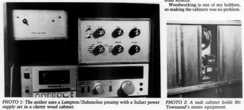
Will enjoy these photos of some of my audio equipment. Photo 1 shows my Lamp ton/Zukauckas preamp and my Sulzer power supply. I built the preamp from an Old Colony kit. When I plugged in one channel, it failed to work. After a cabinets are made of cherry wood, which I salvaged from a hi-fi built in 1950.
After considering several materials for visual inspection, I discovered that a ground connection had not been soldered. After soldering the connection, the unit worked beautifully, and I have been very pleased with it ever since. The front panel, I settled on 1/4-inch clear plastic. After cutting all the holes, I sprayed the back of it with gold lacquer.
This goes very well with the natural finish of the cherry.
The cabinet for the stereo equipment (Photo 2) is made of teak, with an oil finish. It includes space for a preamp, cassette deck and FM tuner in the first section; a reel-to-reel tape deck in the center; and a record player in the third section. In the bottom compartment is the power amplifier and record storage space. My main amplifier is a Universal Tiger, 100W/channel, which I built from scratch.
.
PHOTO 1; PHOTO 2: A teak cabinet holds Mr. Townsend's stereo equipment.
Woodworking is one of my hobbies, so making the cabinets was no problem.
LETTERS
ON “MILLER EFFECT” As a New reader Of TAA (four issues), I agree completely with its format and policies. The editorials and articles (especially the 'Shootout' in TAA 2/85) prompted me to write.
It is apparent that many designers, both amateur and professional, are still searching for the “culprits ” that cause systems, that are distortion free and flat from 'DC to light, ” to have different sounds. Common ones, such as the use of inferior components, and interaction of stages via an inadequate power supply are, of course, well known.
One little known and elusive culprit that is often overlooked is called 'Miller Effect.' A triode used as a conventional amplifier will have an input capacity of not just the grid to ground value, but in addition, the plate to grid value multi plied by the gain of the stage. Transistors also exhibit this same characteristic.
Visualize if you will, a high mu (amplification factor), which is a high-gain triode stage with a high-value (250k) gain control in the grid circuit. In reality, although not on the schematic, there is a “capacitor ” between the arm of the pot and ground, and its value may be as high as 100pF.
Depending on the position of the arm, and any other resistance that may be effectively in series, there will be a frequency within the higher portion of the audible spectrum where the capacitive reactance (in ohms) will equal the resistance in series with it. The response at this point will be down only 3dB, but there will be a 45 degree phase shift.
Feedback, of course, can easily correct any deficiency in the frequency response, but can it restore the original phase relationship between the input and output? A cliche I like to use is, “the easiest way to clean up a mess is not to make one in the first place. ” In my 40 years of designing and “scratch ” building, I have never used a 12AX7, nor any of its counterparts or predecessors. My latest (and ultimate) system does not use any triodes unless they are cathode followers which degenerate the “Miller Effect' capacity to near zero, and have a low out put impedance. Though the cathode fol lower has no gain, this is easily overcome by placing a direct coupled low-level, high-gain pentode ahead of it.
The pentode, unjustly shunned by many, is an excellent audio amplifier.
The screen and suppressor grids act as “shields ” between the plate and control grid. Here, there is no Miller Effect and the input capacity is only the grid to ground value (usually only a few pico farads).
The extremely high (almost infinite) internal source resistance of a pentode is not a disadvantage when the next stage is a direct coupled follower. The only load is the plate resistor itself, as there is no coupling capacitor, next-stage grid resistor nor next-stage input capacity.
The gain is very high, the frequency response is excellent, the output is virtually distortion free, without phase shift.
I recently designed, breadboarded and tested to my satisfaction, a cascode/pentode/ follower 'moving coil to auxiliary input ” preamp. It has no controls, only a fixed RIAA passive equalizer. It is located between the direct coupled pentode and follower, and also serves as the plate load for the pentode. Granted the equalizer has inherent phase shift, but (as explained above) there is no additional shift or shunting to disrupt its time constants.
The preamp's frequency response, with the capacitors in the equalizer disconnected, is absolutely flat from 10-50kHz and the voltage gain is 5k.
When I complete a two channel working prototype I will submit it, and if there is sufficient interest it may become a TAA project.
Richard E. GATZKE; Plymouth, MN 55441
USING PAUL'S REGULATOR
I built Four of Mr. Paul's high-voltage, low-impedance, regulators from his article in TAA 2/84, p. 25. The devices are used as sub-regulators on a tube preamp.
I was curious about whether the low impedance (output) of the regulator would be audibly better than the two designs I had been using: a “power to the people ” emitter/ follower regulator with a Darlington configuration and Zeners as the reference voltage supply, and a tube regulator using a 5651A as a reference diode, a 12AT7 as the error amplifier and a 12BH7A as the pass element.
To my surprise, I could hear the difference. Mr. Paul's design seemed to be clearer and more open, especially at low frequencies. Transients are sharp and well defined. The “power to the people ” regulator seemed a bit dry in comparison.
This could be due to the pass transistor on EGC238. I used a 5uF Wonder-Cap for the output cap.
The tube regulator was a bit noisy at low frequencies (intermodulation I presume) when using a moving coil pickup, otherwise the sound was natural. The dynamics were not as good as those resulting when using Mr. Paul's design.
I can easily interchange the regulator boards in my preamp and I am comfort able with the results.
My only dissatisfaction with the Paul regulator is that it takes a full 15 minutes to warm-up and sound its best. Because of the reference voltage resistor/ capacitor time constant, and the temperature effects on the components in the feedback loop, some voltage drift (+ 5V) occurs on the B+ while the regulator warms.
Mr. Paul was very helpful by answering many questions. I have been using his regulators since August without a failure.
I leave my preamp on most of the time, since I do not have auto-muting on the preamp outputs and I do not want to destroy my power amplifier with an improper turn-on.
D.A Lucio; Kalamazoo, MI 49009
SCOPE PRICES GOING DOWN
Since my Review of the Ramsey BS-601 oscilloscope ( TAA 1/85, p. 40) I have ob served a remarkable phenomenon: the BS-601 has inexpensive clones. Lately I cannot flip through an electronics magazine or catalog without seeing that scope turn up again and again. Everybody and their uncle is distributing it, and a price war has developed (lucky us). The folks at Ramsey are apparently keeping up by recently lowering their price $30.
I have compiled a list of distributors for some of the lower priced clones for TAA readers.
Ramsey Electronics
2575 Baird Rd.
Penfield, NY 14626
(Ramsey BS-601, under $370)
Edlie Electronics 2700 Hempstead Trapk.
Levittown, NY 11756
(EICO 482, under $470) (Speco FS-4820, under $400)
Elenco Precision Electronics 616 Wheeling Rd.
Wheeling, IL 60090
(MO-1251, under $526)
Diplomat International 2900 Townsgate Rd., Ste. 100
(Meguro MO-1251, under $376) Fordham Radio 260 Motor Pkwy.
Haupauge, NY 11788
(A.W. Sperry 620C, under $370)
Emco Electronics PO Box 327 Plainview, NY 11803
(OSC-20-DT, under $446)
Deltax Dynamic, Inc.
20955 E. Lycoming St., Ste. 107 Walnut, CA 91789
(DX-5020, under $380) JDR Instruments 1224 S. Bascom Ave.
San Jose, CA 95128 (JDR-2000, under $390)
MCM Electronics 858 E. Congress Pk. Ave.
Centerville, OH 45459 (Tenma 72-320, under $390)
Dick Smith Electronics
390 Convention Way Redwood City, CA 94063 (Q-602, under $400)
Heath Company Benton Harbor, MI 49022 (SO-4221, under $501)
The wide range of prices is amazing when you consider most models are identical except for knob styles. Whoever makes the nameplates must be doing a booming business.
Ben Poehland
Malvern, PA 19355 ahead of each. It would help me if Mr. Boak could answer the following questions:
The output of my power transformers (secondary) will be +55V (as high as +59V). There will be about 30kuF of filter capacitance in each side of the filter. I do not know how to figure values for R4, R5 and Z2 in Boak's regulator.
The Borbely amplifier wants + 55V DC.
From this I think R4 should be 0.10 ohm 5W, R5 should be 0.56-ohm 5W and the Zener should be about 38-40V.
Am I correct in assuming that with Mr. Boak's regulator one need not be too fussy about very low ESR (equivalent series resistance) filter capacitors ahead of it? It seems that a very large filter bank should not be necessary. Is there a per side capacitance value limit when using regulators? I would like to thank Mr. Boak for his contributions and I hope he finds the time to write more articles soon.
Dick Nelson
Simi Valley, CA 93063
Mr. Boak replies:
Your choice of components is almost ideal. Some guidelines might help you to interpolate for future projects. The de sired raw AC (i.e., the transformer secondary) should be about equal to the in tended output DC value (at least in the range of 30-80V). This will make the pre regulator capacitance value less critical.
A good value for the filter capacitors, ahead of the regulator, is about 1kuF per ampere of load current.
The ESR of this cap is important, however, as well as the series inductance. Filter caps tend to have a fair amount of inductance, which reduces their effectiveness at higher frequencies and introduces undesirable phase shifts.
Unfortunately, due to circuit capacitances and inherent limitations in the regulator circuit, the rejection of input shifts is not as good at high frequencies.
Therefore, it is important to bypass the input filter caps with at least 0.22uF of good high-frequency capacitance per 1kuF of filter. Almost no improvement in performance can be gained from additional capacitance ahead of the regulator.
The frequency response of the regulator can be stabilized from DC to over 100kHz by adding output capacitance of about 2.5kuF per ampere of load current.
Bypass this with good low ESR high-frequency caps of about 1uF per amp of load current. The 30kuF you mention should be more than enough for this system.
Your choice of R4 and R5 will yield a current gain of 5.6 over the regulator's capacity. The formula for output current is:
Tout = ((R5/R4) + 1) XLg Ig is usually about 1.7A, so the output current here is on the order of 11A. This should be a good value for the Borbely design.
If you are using either the earlier circuit with a 15V regulator, or if you are using the revised TAA (2/81) regulator circuit then the 38-40V Zener would be correct for Z2. The newer circuit has beter performance, and if you select it you will be using 5V regulators. The correct value of Zener Z4 for this circuit will be 48V.
'PHASE SHIFTER’
Commenting on Mr. R. Chalupa's interesting all-pass 'Phase Shifter' idea proposed in TAA 4/84, p. 43 to mitigate the problem of second-order loudspeaker crossovers, Mr. Chalupa presents a formula for fc and R for the case where R equals C. In this situation the phase lag (shift) across C is 45 degrees, and the 'all pass' will double that shift to 90 degrees.
With his assumption that the shift at crossover should be 180 degrees, Mr. Chalupa is only part way there. The phase shift across C may be expressed:
Phase = -arctan 2 pi f x R x C and the phase shift out of the all-pass is two times that calculation. The minus sign indicates a phase lag with the circuit illustrated.
Also note that this circuit gives a time delay related to the phase shift, which may be calculated:
Phase shift ° 360 delay =
Most texts indicate the formula for 180 degree shift as:
a 10 2pixRxC however, this is an approximation, but close to reality. The IC Op Amp Cook book by Walt Jung (Sams) covers the all pass well.
L.B. Dalzell
El Cajon, CA 92020 SULZER ENHANCED
In response To Charles E. Ulrich's letter on the Sulzer supply in TAA 4/85, I have used the circuit for a one amp supply. I do not use the extra transistor because it decreases performance. Mike Sulzer more or less said this when he mentioned the need for an emitter resistor and possibly extra compensation (and consequently less bandwidth).
However, it is important to choose the pass transistor carefully. After some experimentation I chose the MJE200 (MJE210 for the negative version). This transistor has an Fr of 60MHz and a high, flat He up to a couple of amperes. The maximum Veg is only 25V, which is fine if you use a pre-regulator. I also found that preloading the regulator with some 40-50mA improves its high-frequency response somewhat. My circuit measures less than 0.010 at 100kHz. Incidentally, you can short-circuit-proof the supply by using an 18V or 24V pre-regulator instead of an LM 317 with a Zener. (The LM 317 can only shut down to the Zener voltage and not to zero output.) I have devised a 5.5 by 2.5-inch board to hold the circuit including the pre regulator, fuse holder and rectifier diodes (excluding the filter electrolytics). Adequate heatsink space is available. The negative board is the same size and accepts a T-220 pre-regulator, which limits the output to about 1A. You can go to a 3A with the MJEs by mounting (on a bracket) a TO-3 regulator (3A).
Jan Dibpen W. Germany
If readers are interested in Mr. Didden's circuit and circuit boards, please use …-Ed.
CURCIO'S PREAMP
COMPARISONS building the Curcio preamp, and to up date readers on the latest Hafler modifications from Musical Concepts.
“Daniel ” ( TAA 2/85) is the first project I have built from scratch. I purchased the Old Colony kit, which, of course, pretty much eliminated the problem of hunting down parts. My next problem was finding an appropriate box in which to house it.
Since I was replacing my Conrad-John son PV-1, I finally decided to simply use that to house my Daniel preamp. Of course this meant that I could not sell the PV-1, but I am not sure I could have got ten a better box for what I may have sold the PV-1 for. At any rate, it does make a classy looking preamp. The final piece of the puzzle was finding a box to house the power supply. I was fortunate to be able to find a suitable box on sale at Radio Shack for about $7. Thus, for about $360 I was able to upgrade my preamp from the PV-1 to something comparable to an Audio Research SP-10 (more about this later).
Building the preamp was relatively easy, with few snags. I did have a couple of questions regarding the polarity of one of the regulators, and I want to thank Old Colony for responding so quickly. I mailed my questions from Washington DC on a Monday and had my answer on Friday. That is what I call fast service, and is typical of all my dealings with Old Colony. In fact, one of my questions was about some missing parts and these arrived the day after my letter was sent (do you have a parts department with precognitive abilities?). Less experienced readers who may be wondering how difficult this kit is to build can be assured that if they can build a Heathkit and can identify parts (mainly resistors and capacitors), they will be able to build this preamp.
So, how does it sound? It worked with out a hitch the first time I plugged it in (and every time thereafter), and is a tremendous improvement over the PV-1 with more solid bass, extended highs, better dynamic contrasts, crisper transients and increased transparency. That in itself is a wonderful recommendation, the PV-1 was (and is) a fine vintage tube preamp. More impressive was being able to compare the Curcio with an Audio Research SP-10 at a local high-end dealer.
The speakers were Thiel CS-3s and the amplifiers were by Threshold with an NEC CD player as the source.
The amazing thing about this com parison was how much alike the two preamps sounded. The Audio Research had a slightly heftier low-end (which I preferred), but the Curcio had a slightly smoother high-end (which I also preferred). Soundstaging, tonal coherency, imaging and other characteristics were very similar between the two preamps.
For a $360 preamp to hold its own with a very good $2000+ preamp is pretty remarkable. The dealer and I were both very impressed.
Finally, I'd like to report on a new up date to the Musical Concepts Hafler mods. You may recall I did a kit report on their .M-200C modification for the Hafler DH-200 ( TAA 4/84, p. 50). Since then The Absolute Sound gave a very favorable review to their mod of the Hafler 110 preamp. I recently installed an update kit to transform my amp into the latest Musical Concepts revision, the M-200DX.
This revision is a radical alteration of the Hafler topology involving the removal of one gain state and its associated circuitry, along with revamping the feed back network. The result is a marked improvement in high-end smoothness and detail (clean, silky highs), a reduced sense of grain in the background, and an easy, effortless quality that is a joy to hear. I have not had the opportunity to compare this amp to any commercial models, but it is certainly a worthwhile improvement to the already wonderful M-200C. Cost of the kit to upgrade an unmodified amplifier is $135, and to upgrade from a 200C to a 200DX is $45.
Readers can get information by writing Musical Concepts, 1 Patterson Plaza, Florissant, MO 63031.
Like Old Colony Sound Labs, Musical Concepts provides music lovers, who love to solder, some of the best and most satisfying values around. I highly recommend TAA readers try them both. It's the best way I know of to become an active audio amateur. The rewards, both in terms of pride in quality construction and musical satisfaction, are enormous. I extend my gratitude and my hearty thanks to both!
Teo Kasteuic Cupertino, CA 95014
MUSICAL CONCEPTS' SUPERMOD
About FOUR YEARS ago I installed Musical Concepts' Supermod to my Hafler DH-101 preamp. Every aspect of performance improved: dynamic range, imaging, ambience retrieval, detailing bass solidity and power, to name a few. This original modification was basically a parts upgrade except for improving the stiffness of the power supply by adding much larger filter caps (with small bypass caps). Since that time, Musical Concepts has made evolutionary changes to this modification, and developed a Supermod for the DH-110. This modification has been favorably reviewed in The Absolute Sound, but I have not heard of any newer modifications.
I recently upgraded a used Hafler DH-200 I purchased to replace my tired Dyna 416. Unmodified, the DH-200 sounded all right, but rather bland and unexciting. I missed the sense of control and dynamics that my Dyna 416 gave from the bass through the lower midrange. First, I installed Musical Concepts' M-200 modification, which is nothing more than a capacitor swap and bypassing the electrolytics. The caps sup plied are Electrocube polypropylenes.
The modification mainly increased the information passed throughout the upper midrange and trebles.
Next, I performed the M-220DX modification. It is a major design reworking, by removing two transistors along with many caps and resistors (the power supply remains unchanged). Sonically, it brought changes from the top down; that is, it further cleaned up the highs. This increase in purity extended down into the bass, but I would say that most of the improvement was noticeable from the midrange upward.
After I made the M-200DX modification, it was obvious that the amplifier was letting much more musical information through. Still, it seemed unexciting from the standpoint of dynamics. I thought the power supply was probably at fault.
I replaced the stock power supply caps with Capacitor Technology FA3 (25G075DF1H) series 25k uF. These caps are the same physical size as the stock 10kuF Sangamo caps, so they are very easy to install. To my ears, this last step began to make the DH-200 come into its own. Naturally, the bass seemed deeper and more taut, also more dynamic, but most striking was the increased midrange purity-an added harmonic richness that is less electronic sounding.
Now I found myself not wanting to shut down the stereo after a night's listening. I would recommend the FA 3 caps to any Hafler owner as an inexpensive and easy way to more exciting sound. Musical Concepts charges under $81 for the pair, but the more resourceful reader may be able to find them else where for much less.
The components I used in association with the Hafler electronics are: an Ariston RD11s table with a Mayware MKIV arm, a Grace FE improved pickup, Neglex interconnects, Audioquest Type-6 speaker wire and Infinity RS2.5 speakers.
I do quite a bit of listening on old Stax SR-44 headphones (not the best, but musically satisfying).
Eric ANDERSON; Ankeny, IA 50021
EQUIPMENT TIPS
I cannot BEGIN to tell you how much I look forward to each copy of TAA. I thought I would pass along a couple of tips for your readers. First, those looking for an inexpensive amplifier kit for subwoofers and other devices might look into a kit marketed by Formula International ( 12603 Crenshaw Blvd., Hawthorne, CA 90250). It is a variable-bias, 100W/channel design, uses four output transistors per channel (MJ15002, 15003s) and costs $51 per channel at last check. Second, McGee Radio ( 1901 McGee St., Kansas City, MO 64108) has a grab bag of polystyrene capacitors for 99¢. You get quite a few (20 or so), most of which are not marked for voltage or tolerance, but the ones that are marked are high voltage. Values range from 22pF to 68,000pF.
Bob GRAVLIN; Bonsall, CA 92003
OPEN FORUM
I reap some of the best, and unfortunately some of the worst, writing about the non-commercial audio craft in TAA 1/86. The editorial, technical articles and kit reports in that issue are superior. It has been a while since this much information has been presented in one issue. However, I was dismayed to read two letters which were written, in my opinion, in a highly unprofessional tone. It is regrettable that some people who rightly question the validity of information presented cannot first do a little research on the source of data and then write short tactful letters requesting clarification.
In order to keep us all talking together in the open forum of TAA, we must continue to communicate in a friendly and tactful manner to maintain the high degree of professionalism and goodwill that exists in the non-commercial audio community.
Lez Hutchison Lancaster, CA 93535
CABLE CAUTION
I Have A Note Of caution for anyone using or planning to use Neglex 2534 Quad microphone cable as interlink wire in a hi-fi system. Due to the high capacitance between the shield and the signal wires (approximately 50pF per foot), you might encounter a high-frequency roll off if you are driving a high-impedance load. Sees le,, if 3 feet of cable leads into 100k, using the formula f = % «RC, the signal will be approximately 3dB down at 10kHz, or 9dB down at 20kHz.
After hours of trying to speed up (get high frequency) out of my tube preamp, I finally discovered the problem was with the cable. I removed the shield and kept the wires twisted to prevent radio frequency interference (RFI) and made sure the cables were away from the 120V AC lines and power transformers. Now the sound is great, the bandwidth is beyond audibility, and the sound-stage localization and depth perspective are sharper, greatly improving the attack.
These cables are now the best I have heard.
WiLL FIRSTBROOK; Oakville, Ontario L6L 3B3
William Ruck replies:
Mr. Firstbrook's letter points out an important fact: at times, the total amount of capacitance in a wire can be as critical as its quality. His calculations of the frequency roll-off are, however, incorrect.
The source impedance, rather than the load impedance, is what determines high-frequency roll-off. Referring to a simplified diagram (Fig. 1), you can calculate the effect of various source impedances using the following formula:
Loss (in db) = 20log (i Re) L Big]
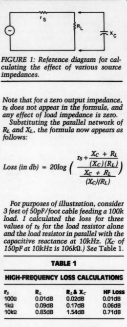
FIGURE 1: Reference diagram for calculating the effect of various source
impedances.
Note that for a zero output impedance, 1s does not appear in the formula, and any effect of load impedance is zero.
Substituting the parallel network of Ry and X;, the formula now appears as follows:
+X + Re Loss (in db) = 20log ( = elu) FY
“oe For purposes of illustration, consider 3 feet of 50pF/foot cable feeding a 100k load. I calculated the loss for three values of rs for the load resistor alone and the load resistor in parallel with the capacitive reactance at 10kHz. (Xc¢ of 150pF at 10kHz is 106k{).) See Table 1.
TABLE 1 HIGH-FREQUENCY LOSS CALCULATIONS
R. R.& Xc
0.01ad8 0.02a8
0.09d8 0.17d8
0.83aB 1.54d8 HF Loss
0.01d8
0.06dB
0.71dB output impedance that more closely resembles the 10 0-ohm figure.
A tube preamp can have an output impedance almost as low if it has a cathode follower, but if its output is taken directly off the plate, the output impedance is closer to 10 k-ohm.
I should mention two other caveats.
In many designs, the circuit cannot supply as much current as its output impedance might lead you to believe. As an example, the 741's output impedance is 75 ohm, but it can supply a maximum short-circuit current of only 25mA.
Among other things, this means that it might not be able to drive a capacitive load at high frequencies, leading to audible distortion as it operates in a current limiting mode while it is trying to follow the input waveform. (Remember TIM?) Finally, Mr. Firstbrook must be in a relatively low-RF area. Twisting the wires shields them from magnetic induction, which is principally 60Hz power line radiation. The overall shield is for electrical induction, which is both 60Hz and RF radiation. Also, tube amplifiers tend to be more linear in the presence of RF, so he might have stray RF in his amplifier, even though he does not hear it.
MOUNTING ALTERNATIVE
THE SEISMIC MOUNTING described by Mr. Ballard ( TAA 1/84, p. 38) is no doubt excellent, but it does require some competence with tools that not every audiophile has. Furthermore, it has no provision for leveling the turntable, which is essential.
Figure 1 shows a system that I have used for many years. It requires no ...
------------
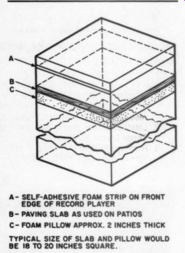
FIGURE 1: The author's anti-microphonic turntable mounting requires no tools and no connection to the turn table.
A- SELF-ADHESIVE FOAM STRIP ON FRONT EDGE OF RECORD PLAYER; B- PAVING SLAB AS USED ON PATIOS; C- FOAM PILLOW APPROX. 2 INCHES THICK TYPICAL SIZE OF SLAB AND PILLOW WOULD BE 18 TO 20 INCHES SQUARE.
--------------
tools nor any connection to the turn table. Leveling is easy to do via card board shims under a corner of the record player. You can obtain the foam pillow from any furniture store and the paving slab from a garden store. In my system, the period of oscillation appears to be about 4 to 5Hz. The self adhesive strip along the front edge of the plinth improves acoustic feedback because it breaks the closed circuit of the often-resonant clear plastic lid and the record-player plinth. You may close the lid during operation without the usual “czonk. ”
GRAHAM WOODVILLE; Aylesbury, England HP17 OLY
FINE TUNING CURCIO
OF ALL THE 1985 Issues of TAA, the one I awaited most impatiently, was number two with the Curcio preamp article. I looked for much comment to follow in 3/85, and was surprised to find none.
Surely the unit has been built and comment has been generated. My opinion still awaits tweaking.
My reference preamp is a Last PAS (see TAA 3, 4:82) with a simple power supply shunt-regulated by OD3s. I built the Curcio unit as shown except for some minor differences in the raw sup ply. Both preamps are phono only with Alps controls and no mode switching.
Both have mylar/polyproplene type composites for the larger capacitors. The non-exotic jacks and wiring do not use POOGE techniques ( TAA 1:81). The Curcio design is elegant and the board layout and quality are superb. It is a clean sounding unit with predictably somewhat stronger and tighter bass than the PAS. All in all very nice.
Presently, I continue to use the PAS because I can still hear a number of details with it that I cannot hear with the Curcio. I strongly suspect this detail is being masked by poor samples of 6D]J8s. I tried a motley mixture of new and used tubes of various manufacture, only to find most of them noisy and microphonic. Some are so sensitive I can hear wind when I blow on them from about a foot away-a far cry from the typical Mullard or Telefunken 12AX7.
A ham radio friend attributes the microphonics to the small elements used in the 6DJ8s, and also suggests they tend to become gassy. I had been some what concerned with the 10M grid return resistor in V102, but had figured the positive reason for its being so high outweighed the possibility of gas upset ting the bias via a loosely controlled grid. However, after testing several tubes in this spot I did not encounter a problem.
Mr. Curcio only hinted at the micro phonics problem in his pre-preamp article ( TAA 5:84), and does not seem to endorse any particular brand of tubes.
Can anyone suggest a source for quiet ones? Mr. Curcio and TAA are to be com mended for this design, which once customized, is likely to become a major contribution to TAA's stable of fine preamp projects.
Doucras R. MARTIN; Ponca City, OK, 74601
Mr. Curcio replies:
Thank you for your kind words regarding the "Daniel" preamp.
Although I have received many letters in response to the article, understand ably at this early date, almost all were concerned with various construction details of the design, such as part number corrections and component substitutions. These comments were compiled and resulted in a correction insert, which did appear in the 3/85 issue.
From the information contained in your letter I share your suspicion that the performance of your preamp is being impaired not only by your choice of tubes but also from another cause. I suggest that you consider the following:
Tube selection. Since the design of the “Daniel ” preamp is such that the tube choice can significantly contribute to the overall sonic character, the expense of high quality tubes is justified (by the way, my choice is the Tungsram E88CC/6922). In addition, since the design employs only local feedback, a performance optimum can be achieved with the hand selection of tubes. This is accomplished by first selecting the two tubes (from a collection of perhaps ten) exhibiting the best noise performance for the V101 and V201 stages (nearest the cartridge).
The remaining tubes should be selected so channel-to-channel gain is identical at both the output of the phono stage and the line stage.
Passive Component Selection. Your letter refers to your use of a ‘mylar/ polypropylene composite' in the larger capacitor positions (although you don't mention the brand), and nothing of the smaller (RIAA) capacitor choices. In the article I have suggested that the design is, in reality, a sonic recipe whose ingredients are the tubes, passive components, and power supply regulator. As such, I recommend that you initially try the type and brand of component specified. In particular pay close attention to the IAR Wondercaps (coupling and bypass), the Transcap (RIAA) capacitors and the carbon composition input and output resistors.
Finally, although there are many quality tube sources, I would recommend for your consideration Douglas Kent Smith Consulting in Pittsburgh, PA (412-322-1693). In addition to a large selection, the quality is high, the price low and the service quick.
AMBISONIC FOLLOW-UP
AFTER READING MR. SOMMERWERCK'S interesting and thorough treatment of Ambisonics ( TAA 3/84, 4/84, 5/84), it is difficult to follow up on your invitation to submit further information. But I will try.
First, I would like to suggest a few minor corrections in Part III. In that issue, Mr. Sommerwerck refers to the Soundfield microphone capsules as hypercardioids. Calrec describes them as
'special sub-cardioids’--that is, they have polar responses somewhere be tween omnidirectional and an ordinary cardioid.
Also in Part III on page 40, the right hand column contains some references to “left rear, ” 'right front,' and so on, in connection with the W, X and Y signals. These are, of course, unrelated. On page 41, the box headed “Ambisonic En coding and Decoding ” contains incorrect weighting factors for B-format signals. They should read as follows:
W=1
X = radic 2cos theta, cos theta
Y = radic 2sin theta, cos theta
Z = radic 2 sin theta
The radical 2 factors are due to the additional gain applied to the velocity microphones. Decoding weight is the inverse of the above.
On page 36 of Part III, the price of the Soundfield microphone is incorrectly given as $8,000. This mike is currently designated the Mark IV and is priced at
$4,990. For this modest sum, you get, among other things, the microphone and its control unit, which can provide endless entertainment. The unit has two types of output, which are available simultaneously. The first output is B format--i.e., the W, X, Y, Z signals- which would be recorded on a four channel unit. The other output is stereo.
The Mark IV has plenty of controls, but only two groups are of interest here.
The first is labeled 'sound field.' These controls allow you, in effect, to do the following:
Rotate the microphone in a plane that is normal to the long axis of the microphone unit. This plane is generally horizontal or close to it, depending on how much the microphone is tilted.
Tilt the microphone in a vertical plane.
Move the microphone near to or farther from the sound source.
Note that no real movement of the microphone is involved. The effects are produced by simple processing of the W, X, Y, Z signals in various ways.
The control unit uses the B-format signal to synthesize a coincident stereo pair microphone. The second group of controls allows you to adjust the effective angle between the synthesized pair of capsules and to vary the polar responses from omnidirectional, through all cardioid types, to figure-8.
In summary, you can adjust the microphone to get the desired results.
And here is the real magic: if the recording is done in B-format, then all the above functions are available on replay.
This means that you do not have to choose the microphone setup prior to or during the recording; the listener chooses it during playback.
I would like to mention two other things about the control unit. Because the microphone capsules are (sub)cardioids, the low-frequency response rolls off. This roll-off is removed by equalization within the control unit. The other trick is to make the capsule array appear to be coincident. In the microphone, the capsules are arranged on the faces of an imaginary tetrahedron and so are equi distant from a central point inside the array. The B-format signals (W, X, Y, Z) are supposed to be those signals that come from a coincident set of three figure-8s and an omnidirectional capsule--i.e., they all should occupy the central point mentioned above. The control unit applies correction to the signals actually produced by the capsules to generate a new set of signals that closely resemble those that would have come from a coincident set of capsules as specified above.
Ambisonic theory allows you to use any number of speakers, each driven in a prescribed way. For horizontal surround sound, a minimum of four identical speakers is required, with six speakers providing improved performance. Horizontal surround-sound de coders are driven with W, X, Y signals, and they provide four, six or however many outputs. Also needed are at least three shelving filters and a layout control for non-square speaker arrangements. Ten op amps are required to do the job well. Things are more complicated if periphonic (i.e., with-height) replay is desired.
In TAA 5/84 (p. 52), John Roberts questions the usefulness of the vertical component as a source of directional in formation. It is incorrect to discount the Z contribution on the grounds that 'At a live concert, only the sounds coming directly from the orchestra have any useful localization information.' Discounters, pace Mr. Roberts, generally do so without experimental evidence, and they appeal to logic and common sense.
Unfortunately, or perhaps fortunately, the human senses do not invoke logic and other constructs of the human intellect. The current belief is that our determination of the direction of a sound is accomplished using many mechanisms, one (some?) of which involves ambience.
Ambience is not directionless; it comes to us from all directions and is specific to the environment. Synthesized ambience is synthesized ambience. It might even be convincingly realistic, but it is not the ambience of the hall in which the recording was made, nor does it re-create the directional properties of the ambience.
Because ambience enhances the direction-determining function of the hearing system in some circumstances, ambience should be correctly recorded and re-created during replay.
Use of the Soundfield microphone reveals that the Z component is of the same order of magnitude as the other components. So there is obviously something there-perhaps one third of the directional information? Even the horizontal signals seem to contain some height information. When I was first trying out a Soundfield mike, I put it in my back yard and proceeded to record, in B-format, the neighborhood and its animal kingdom. When I replay this tape in horizontal surround sound-i.e., when the Z component is not used- and all four speakers are well below ear level, the recorded aircraft clearly appear to fly overhead. Even though I know I am being fooled, I can not get those planes to come off the ceiling.
When I asked Michael Gerzon (who has written extensively on Ambisonics) for his comments on my obviously failing senses, he came to my rescue by suggesting the following explanation.
Sounds coming from above are reflected by the ground. These reflections bear characteristics that we associate with overhead sounds. Because these sounds will be captured in part within the W, X, Y signals, these characteristics will appear in sounds coming from the horizontal surround-sound speakers. The hearing mechanism, recognizing these characteristics, decides that the sounds come from overhead. So perhaps we can manage without the Z component? Mr. Gerzon has stated somewhere that the musical balance is improved when going from horizontal surround sound to periphony. Presumably this is because the re-created sound field at the ears is closer to our normal listening experience.
In Part III (p. 36), Mr. Sommerwerck writes, “...Ambisonics is the most important development in sound recording and reproduction since the advent of electrical recording.... ” I agree more than disagree with this statement. The main reason for my going to the Sound field microphone and Ambisonics is that there is a limit to how close a stereo system can get to reality. Once you have a good stereo system, where do you go from there? Pour large sums of money into stereo and get diminishing returns? Or go to a process that at least has the potential for getting much closer to reality? It is not a selfish move either.
The audio industry will be pleasantly surprised when asked to supply eight speakers, eight power amplifiers, and so on, in large quantities. Support your local dealer; surprise your lending in stitution. Go Ambisonic!
WiLLiam R. CrAWFORD; Poughkeepsie, NY 12603
Editor's Note:
Mr. Crawford has supplied a list of additional sources of Ambisonic information. To obtain a copy of that list, send a self-addressed, stamped envelope to TAA, PO Box 576, Peterborough, NH, 03458.
Mr. Sommerwerck replies:
I appreciate the time William Crawford has taken to write his humorous and in formative letter. It is great to know that other workers in the field are spreading the gospel of Ambisonics. Mr. Crawford is a serious amateur recordist and is fortunate enough to own a Soundfield mike, along with the associated en coders and processors. I hope his luck in finding worthwhile things to record is equal to the quality of recording he can supply! With the exception of my references to the four tracks of a four-channel recorder in terms of their quadraphonic speaker relationships (which was in tended to reduce any confusion about which track was which), I plead guilty to the listed errors. May I offer a few lame excuses? Long ago, I read that the Soundfield mike used hypercardioid capsules, and I never bothered to double-check. Also, I knew about the Mark IV version, but forgot to change the references. As for getting the encoded equations wrong, I am so used to thinking of three-channel Ambisonics and in terms of the (supposed) orthogonality of the three figure-8 components that I forgot about the “full ” equation. It appears very rarely in Ambisonic literature, although it is in plain view on page 9 of 'Encoding Standards for NRDC UHJ Surround Sound’. I had never really thought it through, and when Mr. Crawford's letter came, I was ready to reject the equations.
At first glance, they do seem odd. Why should the angle of elevation weight the horizontal components? But if you visualize a figure-8 pickup in its full three dimensional pattern as two basketballs super-glued together (rather than as two circles on a flat plane), you will readily see how the X and Y outputs also vary with the height of sources.
The effect of this variation is to make any sounds above or below the plane of the Soundfield mike weaker in the X and Y channels. This, in turn, would tend to mis-position the sounds in non-periphonic reproduction, moving them closer to the listener. (For a sound source moving on the [imaginary] surface of a sphere around the listener, this is technically correct, as any movement up or down brings the source closer to the listener, in the listener's plane. But it is not apt for fixed sources, such as a rank of organ pipes high on the wall.) For a sound source 45 degrees above the plane (an extreme situation for most recordings), the error would be only 3dB, which is not serious.
I do not know what happened to the J2 factors. I never did like them (the idea, as I understand it, is to get more signal on the tape, as the system designers do not care much for noise reduction systems), so I unconsciously left them out. I might also have felt that because they have nothing to do with the basic encoding principles, it was less confusing to ignore them.
There was not enough room in the article to give a full explanation of the Soundfield mike's capabilities; Mr.
Crawford's letter is a good excuse to publish them. I would disagree a bit with one point. It is not quite correct to say you can electrically “move ” the Soundfield mike closer to or farther from the sound source (any more than the operation of a zoom lens is equivalent to moving physically closer to or farther from the object being photographed).
The effect is more one of a direct/ambient balance shift, although it does also alter the lateral perspective somewhat.
regard to correcting the frequency response of the capsules, it is even more apt to point out that most cardioid mikes show a different frequency response for their omni and figure-8 components. This leads to anomalies in the pickup pattern, which can cause other wise-similar-sounding mikes to show very noticeable differences in the way they render ambience. One of the beauties of the Soundfield system is that the separation of the capsules' outputs into omni and figure-8 components allows each to be separately equalized.
This technique could just as well be applied to single-point stereo mikes, but no one seems ever to have done it.
People who have heard full periphonic (with-height) reproduction say that it is as big an improvement over planar Ambisonics as Ambisonics is over stereo. I find that hard to believe, but apparently the ear is extremely “aware of” vertical reflections. (Note the vertical asymmetry of the ear, which contributes, via colorations introduced by the pinna folds, to our ability to decide whether sounds come from above or below.) In any case, I left myself an out;
the upper panels of my electrostatics are electrically separate from the lower.
The improvement wrought by Ambsonics is not just that it brings us closer to “reality, ” but that it also removes gross colorations that are inherent in conventional stereo. When ambient sounds are mixed in with the direct, they are psychoacoustically masked, but still physically present. Because they are delayed with respect to the direct sound, they create comb-filter colorations the likes of which you will not believe until you hear them.
THE NAME GAME
Should Audio decide to change your name ( TAA 2/85, p. 6), I advise you to keep your initials TAA and change your full name to The Audiophile Amateur or something similar. Audio's demise is largely of its own making, and it should in no way try to detract from your work.
My interest in audio is mainly musical and in electroacoustic devices.
In a letter to Audio some time ago, I made (unanswered) solicitations for a good audio amp design. Although the scene has changed, the situation has not: where is equipment capable of 90 to 114dB dynamics, which is consistent with future trends? I have now, thanks to TAA, my own ideas about such a design and have completed a wide dynamic, phase-coherent speaker design, which, as with all sonic equipment, shows up in every link in the chain. Although there is no shortage of high-quality equipment on today's hi-fi market, cost limits my choices. Still, I agree with TAA: I will not compromise at the cost of quality.
F.K. MACHMULLER; Tegernseerlandstr 151/5, W. Germany
-------------
CRAMOLIN TRIVIA
I Have No IDEA what this bit of trivia may be good for, but the listing below caught my eye while going through the Patent Office's 'Official Gazette’ and I thought TAA readers may be interested. I had thought Cramolin was a modem product, but it appears I was wrong, unless of course the formula has changed in the past 59 years. Unfortunately the listing does not say what is in Cramolin (I'm even more curious now). Whatever it is, it certainly works. The original name seems to have been “Gramolin, ” but my German is not good enough to deduce the derivation of the name.
For some reason, the positive photoresist materials available in aerosol cans cost about five times what the negative resist costs. Since the main ingredient is usually a cheap cellosolve acetate, I don't under stand the price difference. I am tempted to use only negative photoresist, but the chemicals to make a reversal of the 35mm film are also expensive and difficult to find.
I am still working on a solution to these problems. Has anyone else faced the same dilemma?
---------

U. S. PATENT OFFICE.
Ser. No. 279,426. Richard Scuirer, Muhlacker, Germany, Filed Feb. 13, 1929.
For Cleaning Liquid for Commutators and Collector Rings.
Claims use since May, 1927.
Ser. No. 277,143. , New York, N. Y.
Filed Dec. 22, 1928, CRAMOLIN
For Liquid for Cleaning Commutators and Electrical Contact Surfaces.
Claims use since Oct. 1, 1928
------
A . S. DougLas Pocasset, MA 02559
MORE ON LOUDNESS CONTROLS
In reference To Dan Wilczek's request for a Yamaha-style variable-loudness circuit ( TAA 2/85, p. 58), the 1985 Linear LSI Data and Applications Manual by Signetics contains a balance amplifier circuit that includes a variable-loudness control (p. 9-198). Except for component values, this circuit is virtually identical to the one in my Yamaha CR-800 receiver, which means it provides continuously variable loudness compensation independent of volume control set tings. Although the balance amplifier uses ICs, the loudness circuit itself is little more than a handful of passive components and could easily be incorporated into most preamps. A suggested source for the Signetics manual is Bob Dean Inc., 2415 North Triphammer Road, PO Box E, Ithaca, NY 14851.
Douglas Hutches; Williamsville, NY 14221
ADs
A “loose wire ” heavy vinyl binder which holds eight issues of Audio Amateur data in a readily accessible format. Silk screened cover and spine imprinted with AA's logo in white on a red background.
Each $7.00 Two binders, ea. 6.50 Three or more, ea. 6.00 Postpaid in USA. Outside USA please add S2.
per binder for shipping. Canada must add $4.
for one and $2. for each additional binder.
Boxes: Library quality boxes. 4 x9 x12 ” high, bright orange printed, folding corrugated boxes with handle/label holder to identify contents. Holds three years of Audio Amateur or other valuable magazines in your technical library. Each order supplied with 2. preprinted labels for Audio Amateur and Speaker Builder.
& Two for $7.00 Four for $10.50.
Postpaid in USA. Outside USA please add 25 % for shipping. Canada must add $3. for each set of two boxes and $1. for each additional set of two.
----------------
KT-2: THE BORBELY PREAMP KIT
[TAA 4:85,1:86]
Erno Borbely is, perhaps, best known to us for his work in power amplifier design. The DC100 and SERVO 100 power amplifiers were designed by Mr. Borbely and have found wide acceptance among audiophiles.
His latest offering is a no-compromise preamplifier, which rivals commercial units costing several times the KT-2 kit price. Borbely admits to being a minimalist in some areas.
This preamplifier is minimal only in its elegant simplicity.
The goal of the design was no! to make the unit simple, but to make it as close to perfect as the the art allows. Three requirements competed against each other in the choice of circuit topology and components. The three, sometimes exclusive, design goals are low noise, high gain and wide dynamic range. The preamp first stage satisfies each requirement. The key to meeting these performance requirements is the use of the best available discrete transistors rather than operational amplifier ICs.
The first stage input is directly coupled to the gates of a complementary pair of low noise JFET transistors. The JFETs and a complementary pair of bipolar transistors form a cas caded, complementary, symmetrical, DC coupled amplifier.
The JFET pair is selected at Old Colony for matching drain current characteristic, important for minimum noise. The circuit design, high voltage power supply and device matching, together, support the goals of wide dynamic range, linearity and low noise. This first, and in many ways most critical, gain stage is one of five sections on the input board. The others are two more gain stages, a servo amplifier and part of the RIAA equalization network.
The second gain stage is a complementary, common emitter pair, directly driving a similar output stage. The high signal to-noise ratio established in the first stage is preserved here thanks to Mr. Borbely's choice of transistors. He uses the best available complementary bipolars: ROHM's 2SB737/2SD786 pair. Their outstanding features are low source impedance, good linearity and an extremely low shot/flicker noise contribution.
The servo amplifier is an LF411CN configured to provide useful gain below 1Hz. The servo amp can null input offsets of as much as one hundred millivolts and provides DC coupled performance, eliminating any need for an output coupling capacitor.
The final job given the input circuit board is passive high frequency roll off of the RIAA network. This follows Borbely's philosophy of separating the two tasks of the RIAA net work, allowing a cleaner implementation.
The next board in the amplifier chain is much like the first in design. It contains three complementary gain stages, a servo amp and an active low frequency section of the RIAA network. This board's first stage is a conventional differential amplifier with discrete, constant current sources. Power on this board is 48V, about 18V higher than the first board receives. This board contains regulators for all gain stages.
KT-2 includes five sections for each channel of the stereo preamplifier. Each section is built on its own board. In addition to the two boards of the amplifier proper, there is the tape buffer, line amplifier and power supply. The kit comes complete with two function switches and volume control.
Included are two toroidal power transformers, gold plated connectors and all precision passive and active components.
An article reprint is included. The kit does not contain hook up wire or cable, solder, housing or knobs. If there is interest Old Colony may offer a suitable housing and matching knobs. Shipping within the USA is included in the price.
AVAILABLE FIRST QUARTER 1986. $510.00 Each
-----------
-----------
Also see: A GAIN OF TEN AMPLIFIER by Bernhard F. Muller