THIS PROJECT BEGAN well over a year ago, after a friend began to up date his audio equipment. He did the correct things, lots of looking and listening, and ended by purchasing a pair of large reference type speakers. They, in turn, needed a 'big brutal’ amplifier, and a good quality preamp.
My friend retired his Altec 604Cs in the big reflex boxes, and a pair of good Williamson type amplifiers [D.T.N. not Reg -Ed] I helped him build in the mid sixties. His rationale was that vacuum tubes were becoming a bit scarce, and expensive.
Power Problems
With his new equipment duly in stalled, he could supply AC to the whole system with a short extension cord to the 1kW switch controlled outlet on his preamp. The ‘big brutal' amplifier was a dual 300W unit, leaving 400W for the tuner, turntable, cassette deck and perhaps a CD player. Together they did not need 400W. All should be well. His family could do as they always had, controlling everything from one master switch on the preamp.
Well, the preamp switch lasted about a month and a half. His service shop found a replacement, and in three weeks he was back in operation. The second switch lasted only two weeks. It too had gone galley west, so he came to see me.
When we removed the switch and took it apart for inspection, the overload was obvious. The moving contact was almost gone-vaporized.
We ran the problem down the AC supply to the big amplifier, and found it to be about 6A. Not too bad, but what was it like at turn-on? This posed a bit of a problem until we found a sufficiently sized current transformer to handle what could be a pretty big surge. The current trans former is a large insulated donut with terminals for connecting a measuring device: in this case a scope.
The current transformer is a type of toroid, with a single winding. The hot AC wire is fed through the center of the donut, and a scope is connected to the winding. Current in the wire causes voltage to be induced into the winding, and one may measure the current to voltage relationship. The device must be capable of handling the current and bandwidth. Using a dual-trace memory scope with one channel to the AC, and the other to the current transformer, we tested the turn-on current.
The amplifier has a large bank of electrolytic storage capacitors in the power supply. For each test they were carefully discharged, using a large power resistor with heavy insulated wire and insulated clips. It took us a few trials before we trapped what I had suspected, and in this case the room lights dimmed for an instant.
The problem arose when turn-on was near the crest of the input power wave (either positive or negative).
The peak instantaneous current was well over 300A, while the more nor mal turn-on surges were near 70A.
Turn-on near the beginning of the wave (near the zero crossing) was near 30A.
Looking at the usual power supply (Fig. 1) we saw why the surge developed. The AC was on the primary, and the secondary connects to a solid-state diode bridge. Our references indicated the bridge would handle a 400A surge. When the power supply capacitors are fully discharged ...
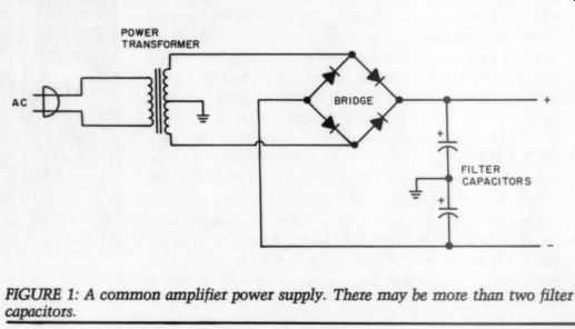
FIGURE 1: A common amplifier power supply. There may be more than two
filter capacitors.
... a short is applied to the power trans former. Now when turn-on comes near the line voltage sine-wave crest (multiply RMS (root mean square) by 1.414), a giant current can result.
Depending on the capacity and various series resistances, the charge on the capacitors will increase and the current will decrease as the difference between the source voltage and the capacitor voltage reduces. The secondary load is, of course, reflected back to the primary. The high current does not last long, but it can do a lot of damage while there.
The rated amplifier power obviously has no relationship to the input AC power. However the amplifier turn on current, when added to the small surges created by the supplies in the other units of the system, was just too much for the preamp switch to handle.
Transformer Trouble
Another factor or two need to be considered in the surge picture. Where on the 60Hz power sine wave was the unit turned off? Was the transformer core left in a magnetized state? If it was, turn-on could result in a saturated core and the surge could be much greater. Also, a very large toroidal transformer is used in the 'big brutal’ amplifier.
A toroidal transformer has a lot to recommend it. Stray fields are well contained, hence induction into the other parts of the circuit are minimized. The efficiency is usually higher, and the regulation better. However, all these factors include a tendency to run hotter as the core is enclosed within the winding.
The toroidal core, a continuous strip of iron, has no magnetic gap as do stacked “E & I ” laminations in a traditional transformer. The gap in creases the resistance to sudden change. Therefore the turn-on surge in a toroidal is usually greater than one in a stacked type of transformer.
From all this information it is easy to see what is required to solve the failing switch problem:
- Turn-on at or very near the zero crossing.
- Turn-off at or very near the zero crossing.
- An ability to handle a whopping surge.
The SSR Solution
A solid-state relay (SSR) meets all three requirements with ease. Let's look at these devices to see how they function, and at some of their uses.
The SSR in Fig. 2 contains silicon controlled rectifiers (SCR) or triacs, plus light emitting diodes (LED) and an optical isolating system so that light is the only connection between the input control and the controlled output. The type we wanted to use included a zero crossing control circuit.
Figure 3, from a General Elec […]
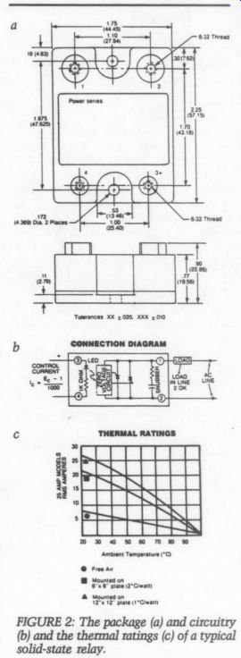
FIGURE 2: The package (a) and circuitry (b) and the thermal ratings
(c) of a typical solid-state relay.
[…]
here, but they have many uses for other situations. As SCRs and triacs are related to rectifier diodes, they too can easily withstand big current surges for limited periods. Further, they turn off at the zero crossing.
Why not use a regular electro magnetic relay? Well, they're not the least bit discriminating about the position on the input wave where they turn on. A magnetic relay operated by DC is pretty good, but the AC operated type can set up quite a hum.
Their contacts can agc and burn, but we shall see some exceptions.
If you ask, “Why didn't the protective circuit breaker on the AC supply open? ” I reply that a circuit breaker is an electro-mechanical device usually designed to withstand surges, and normally has a time delay in operation. Usually a breaker will open if the circuit “fault ” is sustained for a few cycles.
I am mostly familiar with the OPTO-22 SSRs, and I will use them as examples here, however I am sure similar excellent devices are made.
The industry's standard “hockey puck” configuration is available from 5A to 45A, in both 120V and 240V.
These are controlled by low voltage DC, while some are available that may be controlled by 120V AC.
SSR bases are usually a metal heat sink. If operated well within their rated current they produce very little heat. Of course the heatsinking ability of the mounting is important for a heavily loaded relay. The voltage drop across the AC terminals on re lays I have used runs from 1.2V AC to 1.6V AC, so a relay carrying a steady 10A will absorb about 16VA.
I have never found it necessary to mount an SSR on a finned heatsink, such as those commonly used for power transistors, and especially for power FETs (field effect transistor).
More on this later when discussing packaging.
The prime feature in the control is the zero crossing circuitry included as part of the relay. Motorola, with their MOC 3030/3040 series of integrated circuits, makes a six-pin DIP opto coupled, zero crossing driver. The chip could be incorporated into commercial products. Figure 4, from Motorola's specification sheet, shows how the device can be used to drive a pair of SCRs or a Triac. They show the MOC device driven from an IC gate, but many drives can do that job.
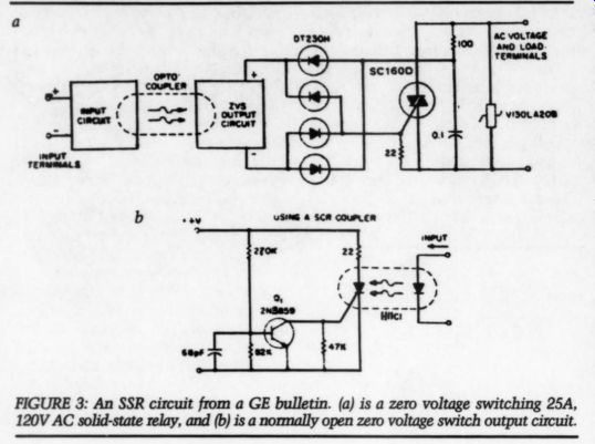
Fig. 3.
I offer one extremely important warning: If you construct an SSR, or use commercial components, remember that you are dealing with line power, and it can be harmful or even lethal. Be careful.
If you purchase SSRs from surplus outlets, consider that while some could be new, many others may have been removed from working devices, and may have been over-stressed. Of the ten surplus units I purchased, two were discarded because the turned-off leakage was over 100mA. The eight others have done just fine.
Construction & Circuits
I find that cast aluminum boxes from BUD, and a number of other sources, work well. The cast boxes drill and machine easily, and the end results look nice. Figure 5 shows a cast box and a drawn box ready for use with SSRs along with the necessary control circuitry. The cast box is a Bud CU-234, which is 4 11/16 by 3 11/16 by 2.25-inches.
In the cast unit a 25A SSR is used to control a Threshold Stasis 300 Type II amplifier. The outlets, from Amphenol, are a socket type with a third-wire ground connection and are mounted with machine screws. The preamp load is very light, being only 45mA at 120V. Also, the amplifier could be placed about eight feet from the rest of the equipment.
The drawn box in Fig. 5 uses snap in three wire sockets, a 10A SSR, a small 12V CT transformer, a bridge rectifier and a 1kuF electrolytic capacitor to filter the DC control voltage. A low voltage lead is taken to a control box with a toggle switch and an LED, which is in series with the control terminals to the SSR. The circuits are shown in Fig. 6. If you use square snap-in sockets punch a round hole and file it to the required 5/4 dimension.
I mounted SSRs in both boxes using a dab of heatsink compound.
Thus, the whole box acts as a heat sink. So far, all my units have operated coolly.
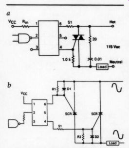
FIGURE 4: A Motorola specification sheet covering the MOC 3030/3040
series of OPTO-ISOLATOR. The device in 4a is shown with a Triac, and
in 4b using a pair of SCRs.
When making these boxed units follow the standard color code as shown in Table 1.
In the drawn box in Fig. 5, I mounted an external toggle switch and LED in a small cast box, 3.7; by 1.5 by 1.25 inches. The switch controls the DC to the SSR, with the LED in series. A series LED drops the voltage to the SSR by about 2V, and it serves as a good indicator. On and off switching seems instantaneous with no noticeable delay.
I was asked recently if it is possible to design a sequential turn-on arrangement. The system had a number of large pieces of audio and video gear, and certain items needed to be turned on first. This is often the case when active crossovers and preamps could cause a “bang ” in a system. I decided a sequencer that could turn on the equipment in about one second steps would be a good choice.
The sequencing can be done in many ways, and Fig. 7 is the design I chose.
I used an Intersil CMOS version of the well known 555 timer, the IPA 7555 (available from Jameco). It can easily be arranged to put out even square-wave pulses. The idea was suggested by Walt Jung, and published in Electronic Design, May 10, 1979.
The basic idea is to feed back the output at pin 3 to pins 2 and 6. The standard 555 does not function with this arrangement, due to the bi-polar inputs that take a lot more current.
I understand that Radio Shack did distribute this item, but they have replaced it with another make of CMOS device. I have been unable to get one for trial.
Please note that Rt and Ct control the duration of the timing period. It may be calculated as T=1.386RC.
For stability, I used a 1uF film capacitor. I had some Wima mylar units on hand, but I found the Panasonic V series (available from Digi-Key) to be satisfactory.
I used a 723k one percent resistor for the Rt. A 2k resistor ties the out put of the 7555 to the clock input of a CD4017, which is a decade counter that marks the ten outputs (0 to 9) one at a time as it is stepped forward by the pulses from the 7555. A zero set network consisting of a 1M resistor and a 0.1uF capacitor sets the CD4071 to the zero position at turn-on. The zero output of the CD4071 is not used because its output is high at turn-on.
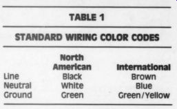
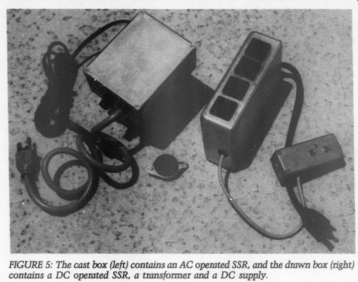
FIGURE 5: The cast box (left) contains an AC operated SSR, and the drawn
box (right) contains a DC operated SSR, a transformer and a DC supply.
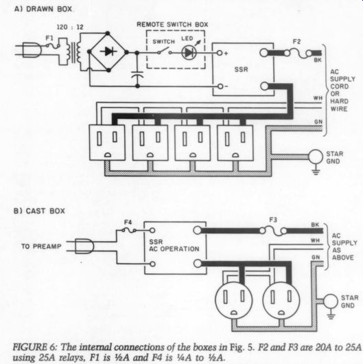
FIGURE 6..
When any used output goes high (positive) it fires a small SCR, an C103B, which remains on until the DC is gone from its anode. The fired SCR connects the negative control terminal of its SSR to ground. And, with the control circuit positive connected to the SSR's plus control terminal, that SSR is turned on to apply AC to its associated outlet.
The next pulse from the 7555 advances the high condition to the next terminal in the numeric sequence, and turn-on repeats for the next SSR.
---------
TABLE 1 STANDARD WIRING COLOR CODES
North American Black White Green International Brown Blue Green/Yellow Line Neutral Ground-
-------------
Of course it is possible to skip terminals to give a two or more second delay. The one second delay is far from sacred, and you may use longer or shorter times, depending on your requirements.
I made a circuit board Fig 8. that connects the rectifier diodes, filter capacitor, an 78L12 regulator to feed the CMOS devices and some helpful 0.1uF capacitors. The C103B SCRs are also accommodated, as are the gate-feed resistors, and the dV-dT resistors from the gates to ground.
The 2N5064 SCR may be used in place of the C103B.
As both of these devices are rated for 200V and 800mA you may won der if lower voltage devices are desirable. I find that the small SCRs fire and control just fine, and they have that nice safety factor. The SCRs turn off only when the voltage drops very low, and this brings up a consideration for the control power supply which is perhaps best explained from experience.
Some Modifications
An associate of mine built one of the sequencers to see whether it was easy. He is a purist, so he used an immense filter capacitor for the power supply (a 30kuF, 25V if I recall). We turned it on, and after a few seconds the circuit went through the sequence perfectly. Then we turned it off, and waited, and waited. In about six minutes it turned off.
This shows that you can over-do the filtering. If you have something around 15V to 25V on the control power supply, the SSR will act as though you used a battery. (i.e., the control voltage ripple does not bother the SSR and will be fully on, provided the trough on the ripple does not drop below about 12V.)
FIGURE 7: The sequencer circuit.
I have used 0.1uF capacitors on both sides of the 78L12, and 1uF tantalum types with complete satisfaction. Therefore, the ripple should not give any concern. When a main filter capacitor of 470 to 1kuF is used, the ripple is satisfactory. The electrolytics discharge fairly quickly, but do not expect to turn the unit off and immediately turn-on again. You must allow the DC to reduce enough to let the C103B SCR's turn off normally about 30 seconds. I feel this time lag is practical in service.
The basing of the C103 and the 2N5064 are similar, anode, gate and cathode, but are opposite as related to the flat on the package. Basing of the 78L12 is also shown in Fig. 9.
The CD4017 requires that pin 13 be grounded to accept pulses. With this connection the CD4017 will turn each connected SCR “on, ” and will then go around again, marking each SCR in turn. This has no effect on the fired SCRs as they remain in the con ducting state, as long as DC is on their anodes.
An alternative connection is avail able, and if pins 11 and 13 are tied together the CD4017 will stop on the ninth count. The option is yours, however 1 prefer the continuous count mode in the event a power “glitch ” turns an SCR off. This is only theoretical. No problems have arisen to indicate a firm choice.
Table 2 shows the pin connections of the integrated circuits. Common plus is taken from a pad next to the electrolytic positive terminal, and looped to each SSR used in the sequencer.
Packaging
Packaging can be as varied as your imagination allows, with consideration for electrical protection and heat sinking. Figure 10 shows one such packaged sequencer, containing four SSRs and the control unit, built into a 6 by 8 by 4-inch standard electrical junction box. This allowed the electrician to use standard conduit and fittings for the permanent installation.
The board and a Signal 241-4-12 transformer are installed in the bottom for the box. Four SSRs are mounted to a 3/4 inch aluminum ...
-------------
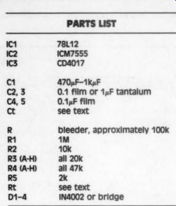
PARTS LIST 78112 ICM7555 CDa017 470uF-1KuF
0.1 film or 1 uF tantalum
0.1 uF film see text bleeder, approximately 100k Mm 10k all 20k all 47k 2k see text IN4A002 or bridge 32 2882
{R32 D1-4
----------------------
... plate that is then mounted to the front panel using 1-inch stand-offs. A metal shop cut the 15/16 inch square holes for the snap-in outlets. I later found similar boxes listed in electrical supply catalogues.
The two-wire cord for the preamp is permanently wired, using a strain relief, and it connects to the trans former through a 0.5A fuse.
I have made a number of other sequencers just for the practical experience. One unit is set up for rack mounting. Its box is aluminum, and measures 3 by 5 by 17 inches. A standard mounting plate is bolted to the front. On the rear of the box are ...
-------------------
TABLE 2 PIN CONNECTIONS OF THE CD-4017 CONOOTUVEBEWN-20 1 ” Positive DC 16 Ground 8 Reset 15 Inhibit 13 Clock in 14
-----------------
Pin Arrangement for the ICM7555
FUNCTION Ground Trigger Output Reset Control Voltage Threshold Discharge Positive DC PIN NUMBER
------------------------
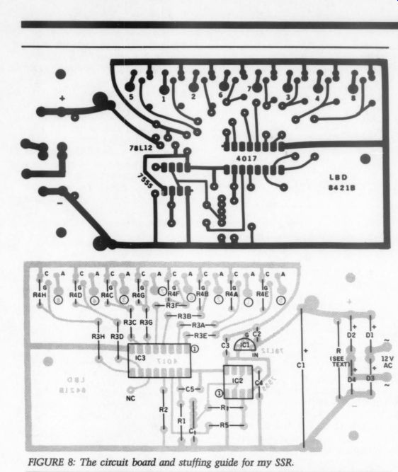
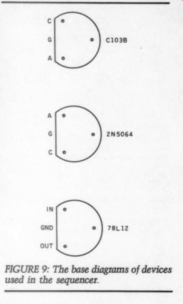
FIGURE 9: The base diagrams of devices used in the sequencer.
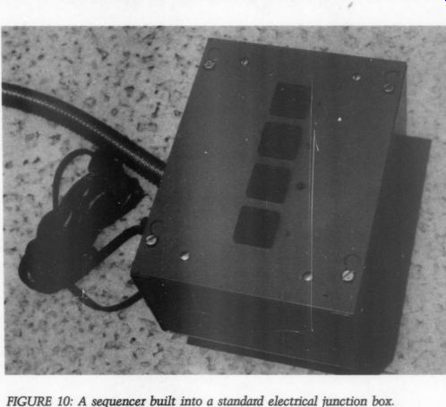
FIGURE 10: A sequencer built into a standard electrical junction box.
... outlets (eight in this case), the preamp cord and a fitting for the electrical supply.
Fuses are used in series with the AC supply to protect each SSR. As an afterthought, LEDs may have been used in series with each SSR control to indicate, on the front panel, that the devices had operated.
Random Thoughts on SSRs
An associate and I wondered whether the SSR would contribute any distortion so we got borrowed an Hewlett-Packard 339A and made a long series of tests. In no case was it possible to measure any change in total harmonic distortion (THD) on any amp tested, nor on any preamp.
It may be possible to use a small, common calculator transformer, but be wary. I find these little plug-in supplies are not always able to per form as marked. The one I refer to is marked 9V AC, 100mA. The open AC is around 28V. I found by loading it to 100mA that the AC drops to almost 9V. If you use this type of transformer test it first to determine whether the open circuit AC is too high or not.
Transformers can be a problem. For example, we tried a small mail order 12.6V 100mA transformer and found it unusable. To test a transformer, just connect AC to the primary and leave the secondary open and running for a couple of hours.
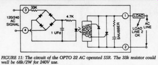
FIGURE 11: The circuit of the OPTO 22 AC operated SSR. The 33k resistor
could well be 68k/2W for 240V use.
The transformer should not be hot. Our rejected sample became too hot to touch comfortably. Signal 241-3-12 transformers and some from Radio Shack, ran cool in this test.
If a cord is chosen to feed AC to the sequencer, carefully check the moulded-plug style cords. Commonly available cords are 16-gaugewire, and are rated for 10A. If higher cur rent is possible, choose a heavier gauge cord, and fit it with a 15A plug.
It is often desirable to 'bunch' a group of wires. Barrier strips, the single row type, can be found equipped with “U” shaped, dual push-on 0.250-inch male connectors. Also, metal jumper units used for connecting two adjacent terminals, are useful for “bunching. ”
The ground (green) wire should be connected to the box. A solder lug with a lock washer mounting hole can be used on the inside SSR mount ing, for soldering the ground. Alter natively, a number of such lugs may be screw-fastened to the box, and the green wire, plus wires to the ground terminal of each outlet, can connect to this “star” ground.
Protection of valuable audio gear, for me, is a must. Metal oxide varistor devices, or similar items, are readily available and I cannot over emphasize their value. General Electric makes a plug-in package, the GESP-752, that has a three wire plug, with a three wire socket on the other end. Recently, tree removal a few blocks away caused extensive damage in my neighborhood. I lost some of the GESP-752s, but that was all. [See also Bill Ruck's articles on Noise in TAA 1 and 2/85-Ed]
Figure 11 shows the internal circuit of the Opto-22 AC operated re lay. This circuit does obviate the need for an input transformer and associated circuitry, but observe some precautions should you decide to use the idea. The positive output of the bridge will show about 15V across the required filter capacitor, providing the circuit is loaded. A low voltage capacitor could be used, say a 1uF 25V tantalum or a film unit.
The 15V pertains, because as cur rent is drawn about 105V is dropped across the 33k resistor. Should the load go open (i.e., the internal LED in the SSR or the 4.7k current limiting resistor), the voltage across the capacitor would rise to 1.414 times the line voltage (around 170V with a 120V AC supply). This could play havoc with the filter capacitor. Such a circuit should be approached with extreme care when used with a DC operated relay to be sure all of the components are well isolated from the grounded box. A 1W 33k seems fine, a wire-wound is best.
While the sequencer was designed for the one purpose outlined here, it could have many other uses. The C103B SCRs will easily drive electro mechanical relays and related de vices. The 800mA capability allows lots of range.
Some Class-A amplifiers (i.e. space heaters) have many filter capacitors.
One I tested drew steady 12.5A at 120V. A 25A SSR handled the load quite well.
Designers have not given sufficient attention to the power supplies, although they can create problems. A “soft-start ” supply would be a refreshing novelty.
Triac and SCR dimmers were well known for their ability to add noise and hash to a line. Later devices use chokes and some capacitive filtration to control the “hash.” The noise, usually in the RF part of the spectrum, is due to the phase delay turn-on where the power sine-wave could be quite high when the device turned on fast, thus developing a series of harmonics into the RF region.
A 'Zero-Voltage Switching' SSR will turn on just slightly after the wave crosses the zero line. The turn on is fast, but the voltage is low, hence the effect is extremely small.
Further, almost all SSRs contain a “snubbing” circuit, a simple series resistor and capacitor, which controls the dV/dT, or the change in voltage with time change to prevent a false turn-on. In addition, the snubber virtually eliminates noise effects.
----------------
ABOUT THE AUTHOR: Mr. Dalzell recently retired after a long career with the Bell System, where he did mostly engineering and circuit design work. He's been interested in audio since the early 50s, and has had several articles published in Audio starting as early as 1959. He is spending some of his retirement designing audio related devices.
Those interested in a possible circuit board for this project (Est. cost $5.50) . If sufficient numbers are interested you will be notified of avail ability and price.
-------------
SOURCES FOR SOLID-STATE RELAYS
OPTO-22
15461 Springdale St.
Huntington Beach, CA 92649
Gordos Arkansas 1000 N. Second St.
Rogers, AR 72756
International Rectifier Crydom Division 1521 Grand Ave.
El Segundo, CA 90245
COMPONENT SOURCES
Digi-Key PO Box 677 701 Broods Ave. So.
Thief River Falls, MN 56701
Electric Switches, Inc.
2478 Fletcher Dr.
Los Angeles, CA 90039
Jameco Electronics
1355 Shoreway Rd.
Belmont, CA 94002
Mouser Electronics
PO Box 9003 Lakeside, CA, 92040
---------
DALZELL POSTSCRIPT
One user of author Dalzell's relays reports an occasional glitch: his sequencer turns on two outlets simultaneously. ICZ has very fast squarewave rise-times and can overshoot. The cure: Solder one end of a 360pF mica capacitor to the end of R5 connected to pin 14 of IC3, and the other end of the cap to ground. The 50-100k bleeder parallel to C1 is necessary in such case. -Ed.
-------
Also see: A GAIN OF TEN AMPLIFIER by Bernhard F. Muller