MODIFYING YAMAHA'S CD2 CD Player
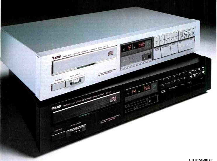
by Hampton Childress
(also see this ad of the CD-2 from 1984)
Of all the controversial audio topics of the 1980s, the CD player stands out as the most promising improvement in home music re production. Even when you consider the CD player (and/or the compact disc itself) has been accused of irrevocable faults, this medium has so many desirable features it is unreasonable to dismiss it as a high fidelity item without first investigating all the avenues for its improvement.
I am the assistant principal contra-bassist in the Baltimore Symphony Orchestra. Part of my job is attending concerts and studying recordings to learn how other orchestras perform.
No matter how good my audio sys tem gets, however, it will never be able to make me think that I am in the concert hall. I do not imply I am unable to enjoy the aesthetics of a recording in my home, but simply that I don't have 80-foot ceilings with hanging reflective disks. The sound can't rebound and resonate as it does at Meyerhoff Symphony Hall in Baltimore. This discussion has been purely on the audible and leaves out the visual dimension, which I find very interesting in concert and somewhat less so at home.
One of my requirements when listening to recordings has always been clean, accurate, and detailed bass reproduction. I don't usually turn up my system to earth-shaking levels because I am not necessarily looking for gut-wrenching 20Hz bass drum response. Instead I need to be able to discern the subtlest overtones on the contrabass and other instruments, to determine how a passage is being played. A large part of music-making is phrasing, and when the whole orchestra is playing it is extremely difficult to hear whether or not the basses have changed bow direction in the middle of a slur. In the past, this kind of low-level detail has been lost in vinyl noise. The advent of the low noise compact disc, however, has changed that.
Although I am not a skeptical man, I held off buying my CD player be cause there were so many negative reviews of the first generation players. The problems were mainly sound quality and mechanical integrity.
One particular unit was dubbed the best-sounding CD player on the market, if you could find one that worked.
As far as I can tell, mechanical problems have been minimized, which leaves us with a multitude of discriminating critics who believe CD players sound harsh, strident, or just 'not quite right.' Having removed the covers from several CD players, I have gained in sight into why some critics argue against CD sound. In all the low to mid-priced units I have seen, sub premium resistors, capacitors, wiring, and integrated circuits abound.
These components are all located directly in the signal path within the player's analog section. The suggested modifications which follow are all in the analog section of the Yamaha CD2. Even if you own or are considering purchasing a different brand, you still may find the modification information useful. Although the Philips and Sony circuitry will be somewhat different, the basis for all the mods is a point of reference from which you can work to improve your unit. Other manufacturers known to utilize Yamaha technology include Sherwood, Carver, and Marantz (some of the newer units). There may be several others as well. You can tell only by opening the lid and looking.
Interesting discussions abound as to which brand is best to modify.
Many audiophiles, willing to listen to CDs, believe the Philips circuitry is best. I don't care to dispute this point, except to say that after making these mods on my Yamaha, it sounds at least as good as the best modified Philips units I have heard. The difference in circuit topology is mainly digital and digital-to-analog conversion. The Magnavox 2040, for in stance, uses two Signetics-made 14-bit D/A converters. The Yamaha uses one 16-bit Burr-Brown unit, which requires a deglitcher, not needed by the Signetics device.
On the other hand, the Signetics D/A has several ceramic capacitors attached to it which must be im proved for good sound. The phase delay from demultiplexing a single D/A signal into stereo is on the order of 4usecs in the Yamaha. I can't say whether or not that can be heard, but I have my doubts. At any rate, this delay can probably be shortened, and because I am ceaselessly amazed by the detail discriminated by the human ear, I will attempt to improve upon this.
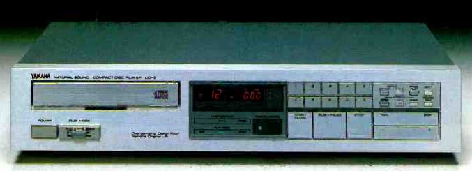
My principal object in opening my CD player was to learn how it worked. I was not dissatisfied with the sound of my Yamaha (or others I have heard) right out of the box. On the contrary, I enjoyed it for some months before I began to modify it.
Once I started poking around inside my CD2, I found many of the same theories I used to improve other audio gear might serve here as well. Once I began work, I was surprised what could be done to make an already satisfactory mid-priced unit sound very sophisticated.
I have become a believer in the CD medium as a result of this work, and have realized sound quality equal to or, in many instances, better than my analog phonograph. General improvements resulting from the modifications included wider and deeper soundstaging, cleaner and more detailed high frequency information, tighter and full bass, tighter and more stable imaging, and overall excellent detail.
If you intend to make the following series of changes to your CD player, beware that you will probably void your warranty. Also, make sure you have a reasonably good technique with a soldering iron. Some areas of the player are tight to work in and if you are not careful it is possible to lift traces off the foil side of the circuit board. None of the following mods are overly difficult, but if you are un comfortable with this kind of work, consult someone who is capable of helping you through the rest of this text to be come familiar with what is required.
No one section is dependent upon any other modification section, so if you do not wish to perform all the mods, select individual areas you wish to improve upon. To achieve the maximum sonic benefit, of course, you will want to perform all of the steps. Other audio enthusiasts will likely continue to find ways to upgrade CD players, so what follows is not necessarily a complete upgrade.
Instead, it is a description of what I have done to gain an enjoyable and educational listening experience.
Begin by ordering the shop manual for your machine. You can contact Yamaha at the address at the end of this article. I was pleased to receive a courteous and timely response from them.
Capacitors
Yamaha made a good start toward achieving POOGE standards by using film caps in some locations. Unfortunately, these are mostly mylar dielectric types. Replace them with equivalent value polypropylene and polystyrene types.
Refer to Diagram A.
1. Carefully desolder and remove the following capacitors:
Part C319, C320 C387, C388 C321, C322 C315, C316
Value 10uF ad uF 3300pF .015uF
... replacing them, one at a time, with premium quality polypropylenes.
NOTES:
a. You should experiment here. I have tried several different types and sizes of capacitors at the output. The best configuration I came up with was paralleling four 1uF Electrocube polypropylene caps. This is only 4uF total, but I don't notice any lack of bass response because of it. That may be, in part, because my Quad ESL 63s don't reproduce the lowest bass tones. More likely, it is because 4uF puts the 3dB down point at 1.6Hz on my system. At any rate, I have found that paralleling several smaller caps give better results than using one large one. No matter what you use, you are almost certain to improve upon the electrolytic coupler being replaced.
b. Try experimenting here by using various capacitor values. This is a shunt across C319, C320 which will add openness, space, and airiness (or whatever you like to call it) to the sound.
c. While experimenting with different values, I found this shunt-to ground has a noticeable effect on the sound. 3300pF is quite large for a final ultrasonic filter and, in fact, dips down into the audible frequency range. You can use a 150pF polystyrene here or possibly eliminate it altogether, depending upon how good the preceding ultrasonic filtering net work is in your unit. If you decide to scale down or eliminate this capacitor, expect a more open and less muffled reproduction.
d. The best solution to using capacitors here is to remove them completely and install the DC servo circuit described in the next section.
No matter what quality, composition, or size capacitor I used, all of them masked the sound more notice ably than a DC offset servo control.
Servo Controlled Output Stage
It has been stated in these pages that the best capacitor is no capacitor at all. To verify this, I present in Fig. 1 a DC offset servo controller used in conjunction with the final amplifier output stage, thus eliminating the output coupling capacitors. IC303 and 304 are the last stage drivers on the CD2, and are designated as IC2 in Fig. 1. The servo circuit and its surrounding circuitry are contained inside the dotted lines. Connections to IC303/304 (IC2) are made as shown outside the dotted line box.
I built this circuit on the foil side of my main CD board, but suggest you do not do it this way. It severely limits access to the solder connections for components underneath. A much better method is to build it on a small piece of perfboard or on one of the Radio Shack IC experimenter boards, and then mount it inside the player. In the CD2, there should be enough space to do this.
Because it is a high impedance circuit, be careful to locate it as close to the output op amps as possible.
Pay special attention to putting the 150k resistor close to the inverting input of IC303-304's replacement.
This circuit can be realized with excellent results using as IC1 a single FET input op amp such as the Motorola MC 34081. The diodes between the non-inverting input and ground eliminate latch-up at power on.
These may not be necessary for all op amps.
I used green LEDs because of their low leakage. If you do the same, make sure they are not exposed to light because they can generate a small current. For best results, pay attention to close tolerance capacitors and matching resistor values. Before operating your player in your audio system, check the output for any DC offset. The servo should bring it to within approximately 1mV of ground.
Resistors
This step will produce subtle sonic improvement, so perform it only if you use the best precision metal film resistors available. Recommended units are by Corning [or Resista-Ed.] and are available from Old Colony.
Refer to Diagram A.
1. Carefully desolder and remove the following resistors one at a time, replacing them with their equivalent value upgrade. All are +1%, %W metal film.
-------
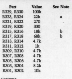
Part R329, R330 R323, R324 R321, R322 R319, R320 R315, R316 R317, R318 R313, R314 R311, R312 R309, R310 R307, R308 R305, R306 R303, R304 R301, R302 NOTES:
-------------
a. These resistors should actually be increased in value to 100k or more. If your preamp has a 25k in put impedance like mine, it is shunting half the available signal current to ground through this resistor in stead of feeding the preamp input.
These resistors, however, appear to stabilize the output. I have received only beneficial effects by increasing their value.
b. Resistors 315-318 are parallel pairs which are part of a filter. If you are cost-conscious, you can just as easily remove the 18k and 68k and replace them with a single R of approximately 14.233k.
2. Power up the CD player and verify proper operation before proceeding to the next section.
Power Supply
The Yamaha power supply consists of a series of pass transistors. As you trace the current path from the rectifiers, each transistor drops the voltage to a lower level for use in different sections of the player. We are most interested in that part of the power supply which feeds current to the analog section. In order to tighten regulation and reduce supply impedance, replace the existing zener diodes and pass transistors with different zeners and adjustable IC regulators. This will have the musical effect of tighter imaging, full bass, and keeping the soundstage full in stead of collapsing inward when a full orchestral climax is reached. Refer to Diagram B and Fig. 2.
1. After noting the position and polarity of the transistor and zener diode, carefully desolder and remove the following parts relating to the positive supply: TR304, R354, D322, C345.
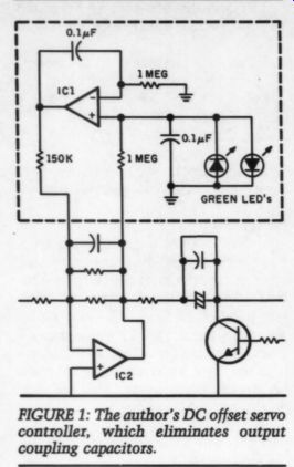
------------ FIGURE 1: The author's DC offset servo controller, which eliminates output coupling capacitors.
2. Bend the leads of an LM317 regulator so the right and center pins (Vian and Vou) are reversed. Place a short piece of sleeving over each lead to insulate them.
3. With the device facing the power transformer, insert the regulator in the holes from TR304. Now the ADJ pin is where the base of TR304 used to be, Vin is connected to the + 18V line, and Vo is connected as the output where TR304's emitter used to be. After verifying correct pin connection, solder down the LM317.
4. Connect a 13V low noise zener diode between the LM317's ADJ pin and ground, using the same D322 holes and polarity.
5. On the foil side of the circuit board, connect a 1000 resistor be tween the LM317's V_out pin and its ADJ pin. This will bias the zener with a very stable current, thereby ensuring zener voltage for tight regulation.
Biasing can be achieved only because the LM317 regulator is self-starting.
If it were not, you would have to supply zener current from the less stable + 18V line.
6. On the foil side of the board, connect a IN4001 diode between the new regulator's Vin and Vout pins, with the cathode (banded end) at the Via pin. Similarly install a 1N4001 diode between the Vout and ADJ pins with the cathode at the V_out pin.
These diodes protect the regulator against reverse biasing when power is switched off.
7. Replace C345 with a high quality 0.01uF polystyrene or polypropylene capacitor.
8. Ensure that no leads will be shorted or parts smashed when the bottom plate is replaced.
9. Double-check each step to verify proper connection of the power supply. An error here can cause un predictable results 'and possible damage to your unit. After you are satisfied all parts are correctly mounted, power up the unit and test for correct voltages at the following locations on the new regulator. If you encounter errors in voltage levels, immediately disconnect your unit from the AC plug and troubleshoot the problems. Do not proceed until all problems are resolved.
Location
Vin pin Vou pin ADJ pin Voltage
18.2V (approx.) 14.2V (approx.) 13V (approx.)
10. Repeat the above steps on the negative regulator with the following changes:
a. Part numbers are: TR307, D323, C346, R355
b. New regulator is an LM337.
c. Omit step 2. The negative regulator can be installed pin for pin, again facing the power transformer.
d. Reverse the polarity of the 1N4001 diodes.
e. Realize that all voltages will be negative.
Power Supply Wiring
To skeptics of this idea, I can only say if you use IC operational amplifiers and haven't completely tweaked your power supply in every single respect, you aren't getting the best possible sound from your system. My experience has been that changing the power supply can produce as many dramatic sonic changes as changing op amps. Supply wiring is no exception.
1. Replace all wiring from the power supply to the analog section of the player by making up lengths of 6P24 OFHC [Oxygen Free High Conductivity] teflon-insulated, silver plated wire. Substitute it for the blue and red twisted pairs (14V lines and 5V line to the D/A converter), and the dual black grounds. [OFHC wire is used for wirewrap and is available from electronics suppliers and computer stores.-Ed.] Op Amps Before all residual digital information from digital-to-analog conversion is filtered out, there is a significant amount of high frequency material which can cause potential problems or many op amps. This material ranges from 20kHz to hundreds of kilohertz. Most of the op-amps used n CD players specify slew rates between .9V and 30V per microsecond.
This should satisfy electrical requirements for the audio spectrum and beyond, however critical listening shows this is insufficient for optimum performance.
Slewing-induced distortion (SID) is not the only problem with op amps used in CD applications. Linearity is degraded in several other ways as well. When you select op amps for premium performance, consider high speed devices which specify a large input dynamic range. (See Walt Jung's article on Op-Amps in this issue.) Also, take into account most CD players use op amps in non inverting configuration. Although this has the advantage of high input impedance, common mode factors are compromised. Select devices which have good common mode specifications.
My choice of the LM318 op amp is based on comparative listening as well as availability and price. It can be bought at most electronics shops for a couple of dollars. It sounds reasonably good, although other available types (such as the Burr Brown 3507-]) are superior. Still, I found it to be a clear upgrade for what was originally in my player. I have verified this result on a friend's Magnavox player. The LM318 slews at approximately 70V per micro second, and can be used without external unity gain compensation. This makes it very easy to work with.
Truly adventurous readers should try other devices as well to determine which one(s) are most satisfactory, according to their personal taste.
Upgrade the op amps to improve high frequency clarity and detail.
This upgrade will also improve fidelity in just about every other sonic respect. The devices used in the Yamaha unit are single inline pin pack ages for which I didn't have suitable pin-for-pin replacements. The easiest way to install new ones is to use replacement units available in TO-99 packages. You will only have to bend the leads. If you intend to use 8-pin DIP packages, install them laying on one side and jumper the necessary pins from the top side of the devices to the SIP holes on the PC board.
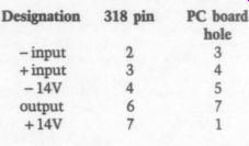
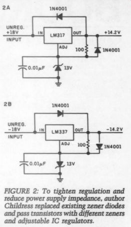
Fig. 2
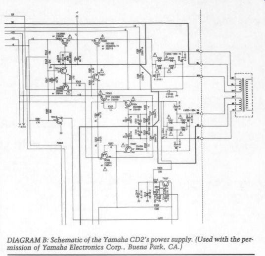
DIAGRAM B: Schematic of the Yamaha CD2's power supply. (Used with the per mission of Yamaha Electronics Corp., Buena Park, CA.)
Refer to Diagram A.
1. Carefully desolder and remove IC301. Replace it with an LM318 by connecting the following pins in the existing holes. To eliminate noise, keep lead lengths as short as possible.
Designation 318 pin PC board hole
- input
+ input
-14V output
+14V
2. Bypass pin 4 of each op amp (pc board hole 5) to ground with a .1uF polystyrene or polypropylene cap.
Make the connections as close to the ICs as possible. Do the same for each op amp at pin 7 to ground (pc board 1IN4001 1N4001 17 hole 1). If you have small enough capacitors, you can do this on the foil side of the circuit board. Be careful that the bottom plate of your player does not smash capacitors or short any connections made on the foil side of the board.
3. Repeat steps 1 and 2 exactly for IC302.
4. Carefully desolder and remove IC303 (9-pin SIP). IC303 is a dual op amp. One section is used for high frequency filtering, and the other section is used as a non-inverting buffer.
After much experimenting I came to the conclusion the buffer amplifier is not entirely necessary. In fact, it slightly degraded the sound no matter what kind of op amp I used to replace it. Jumper this trace on the circuit board (step 6) to eliminate the buffer amp and the need for a replacement dual op amp. If this change produces bad effects, the impedance seen by the following de-emphasis net work (TR311, C316, R311) is probably fluctuating with frequency variations. You may wish to use the additional op amp. I have not been disappointed with the change I made.
5. Replace IC303 by connecting an LM318 as follows:
Designation 318 pin PC board hole
- input 2
+ input 3
-14V 4 output 6 7 +14V 9orl
6. Short holes 2, 3, and 4 by soldering a short bare wire across them.
7. In addition, add a wire between PC board holes 1 and 9.
This connection was done internally by the previous dual op amp to supply cur rent to other circuits.
8. Repeat steps 4, 5, 6, and 7 for IC304.
9. Bypass pin 4 (hole 5) of each op amp to ground with a .1uF polystyrene or polypropylene cap. Make the connections as close to the ICs as possible. Do the same for each op amp at pin 7 to ground (hole 9 or 1).
If you have small enough capacitors, you can do this on the foil side of the circuit board. Be careful that the bottom plate of your player does not smash capacitors or short any connections made on the foil side of the board.
D/A Converter
The digital-to-analog converter used in the Yamaha CD2 is a Burr-Brown PCM53JP-V. The -V on the part number indicates it is a voltage out put model, which has an on-board op amp for current-to-voltage conversion. The PCM53JP is available in a current output model. Its part number is PCM53J-I, the “I ” denoting a current output type. The op-amp used on the voltage output unit is a fast-settling Burr-Brown device specified to slew at 10V per usec.
While these are not undesirable characteristics, you can improve upon them quite a bit, especially when you consider the current out put D/A has an extremely short settling time. I recommend the Burr Brown 3507-j in this application, because it slews at 120V/usec and settles in a fraction of 1-usec. Other devices, such as a fast FET input type will serve as well here. The gain of the op amp in this configuration is 6, so if external compensation is a factor, take that into account when selecting the op amp.
With the Burr-Brown IC, compensation is only required for gains of three or less. One of the pleasures of this worthwhile modification is its electrically simple execution. It only requires the external op amp, the cur rent mode D/A converter, and two capacitors. Refer to Diagram A.
1. Carefully remove IC311 (the existing D/A).
2. Insert five prepared wires in holes 23, 21, 20, 19, and 17. The wires should be 24-gauge and about one inch long with the end going in to the holes stripped about 1/8 ”.
3. Insert the replacement D/A in the holes, being very careful not to bend pins going into holes already occupied by wires. You may find it necessary to slightly enlarge the pc board holes.
4. Solder the D/A and wires to the foil side of the board, making sure the wires and pins are, in fact, both being soldered.
5. Make up a small piece of perf board or Radio Shack experimenters board containing a Burr-Brown 3507-] with .1uF polystyrene or polypropylene caps, which are connected be tween each supply pin (4 and 7) to your ground point.
6. Hold the board as close to the D/A as possible, and determine how long the leads coming from the D/A will need to be to reach the following interconnect points. Keep in mind this is a particularly noisy part of the system, and you must keep lead lengths to an absolute mini mum. It would be a good idea to enclose the op amp board in some type of shield enclosure, although I didn't do that and haven't had any problems. Shorten the leads to optimum length and make the following connections:
Designation Op Amp D/A
i pin 6 17 3 20 2 21 4 19 7 23
Analog Switch-Stereo Demultiplexer
In this step you will replace IC317, an analog switch-demultiplexer, with a high speed CMOS unit such as the RCA CD74HC4053. This will de crease the noise glitch at the output of the device which directly feeds the first IC op amp filter circuit. As a result, it lessens the demand on the op amp and minimizes an unpleasant harmonic generated by the existing switch. The power supply circuit feeding IC317 must be modified.
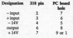
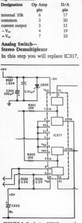
FIGURE 3: Replacing IC317, an analog switch-demultiplexer, with a high speed CMOS unit will decrease the noise glitch at the output of the device which directly feeds the first IC op amp filter circuit.
In stock form, the IC is powered at +5V and -10V. The negative sup ply is taken from the -14V rail and lowered with a resistive voltage divider. Use zener diode regulation for -5V, and improve the filtering capacitance. Refer to Diagram A and Fig. 3.
1. Carefully desolder and remove IC317 (4053 analog switch). Insert in to its socket a CD74HC4053 high speed switch and solder it in place.
Be careful to avoid static discharge into the new IC. This is a CMOS device.
2. Desolder and remove R337 (3.3k), replacing it with a 1.62k resistor.
3. Desolder and remove R338 (10k), replacing it with a 5V zener diode (now called D600). Ensure that the cathode (banded) end is connected to ground.
4. Desolder and remove C324 (22uF), replacing it with a low ESR 220uF electrolytic. Be sure the positive end of the capacitor is connected to ground. Shunt this with a uF film type as well.
Other Modifications
The inductive/ capacitive (LC) 7-pole filter in the analog output is another possible improvement area. I haven't yet determined the best way to go about upgrading this, but one solution might be to build inductorless filters, possibly using an existing op amp. It would be best, I think, not to introduce any extra integrated circuits into the signal path.
To prevent feedback, some audiophiles report good results by insulating their CD players with: cement blocks, rubber feet, and/or other commercially available turn table isolation materials. This makes good sense to me. Gently tapping on the door of my player while it is running causes it to grossly mistrack.
The action is similar to bumping your turntable so that the needle skips several grooves. The Yamaha mutes any strange noises that the error handling circuitry cannot resolve, however.
Manufacturers are advertising better vibration insulation on the newer models, which indicates they recognize the problem is worth their time and money.
I am told that, other than the yarn ball test, no universal vibration/ shock vs. tracking test has been devised. The yarn-ball test consists of dropping a standard ball of yarn from a height of one yard to the top of an active CD player. If your unit cannot pass this test without mistracking, your CD player is a candidate for some type of vibration damping.
Various companies are now marketing disc-shaped dampers designed to ride on top of the disc while it is being played. I have heard reports regarding these devices, but I have yet to try one. My only attempt at using dampers failed when a friend tried to load a Mod Squad damper disc. It was either too thick or too heavy to permit my Yamaha's door to close. Some have tried stacking two discs in the machine. Try that at your own risk.
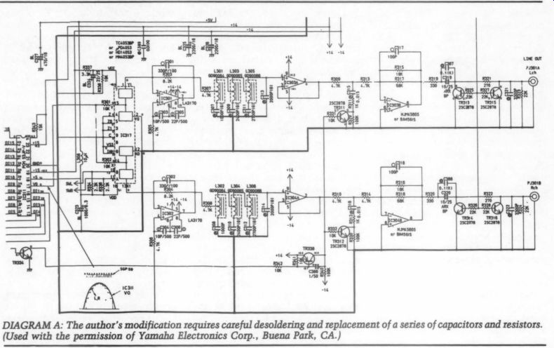
------- Diagram A
Recordings and Performances
A word or two about some of my orchestral recordings may give you a brief insight into my approach to music, audio, and CDs. With the exception of one recording, all my CD purchases have been based on my interest in the .While I am obviously interested in good sound, I can't bring myself to buy recordings advertised as 'Sonic Spectaculars.' The one exception has been Lorin Maazel's recording of Stravinsky's Rite of Spring (Telarc CD-80054), which I insisted the salesman throw in when I bought my player. I wanted to hear what my machine could do when its accelerator was floored. He thought I had to prove to Mrs. Childress that the CD player worked.
At first, I was put off by Maazel's somewhat warped interpretation of the work. He takes liberties with tempi not found in a clearly marked score. Oddly, I have come to enjoy this performance because of that very interpretation. Though the piece is inherently wild and frightening, Maazel adds a new dimension to the meaning of 'bizarre.' Technically, I think this is one of Telarc's best products. It is also one of their earliest on CD. It has the characteristically warm and some what distant Telarc sound, with volume a bit low in order to make room for the bass drum. Imaging is simply awesome. You can hear (and almost see) from left to right, as well as front to back, where each player in the Cleveland Orchestra is sitting.
The front to back depth is almost as clear an image as is the left to right, where we have been spoiled in the past by two-channel stereo.
Another Rite of Spring recording I enjoy is performed by the Orchestre Symphonique de Montreal, under the direction of Charles Dutoit ( London 414 202-2). A sterling performance in every respect it is one of the finest digital recordings London has produced. It has the excellent imaging, detail, dynamics-everything the Telarc has-with a more realistically reproduced bass drum. If you are put off by digital recordings, this one may cause you to reexamine your opinion.
While on the topic of Montreal and Dutoit, I must mention another Lon don digital recording, a Respighi collection which includes The Pines of Rome, The Fountains of Rome, and Feste Romane (London 410 145-2). As above, the digital sound and performance is incredible. This particular conductor and orchestra combination seems to be one of those synergistic relationships which cause your jaw to drop when you hear them. The re corded sound is outstanding in all respects. Particularly in the Feste Romane, thunderous stacatto chords ring to the back of the hall in such a lifelike manner that I believe I can see the wall when I listen.
Dutoit has a way of coaxing the ladies and gentlemen of the orchestra to play with a full, blooming, and, (when called for) outright thunderous sound, without ever str . This session was recorded in Montreal's Cathedral of St. Eustache. It must be a real pleasure to play in that edifice, except for one small problem. I understand outside sounds seep in, so traffic must be stopped all around the structure when recording is in process. I'll bet the townspeople love that.
Mahler's fifth symphony, done by Sir Georg Solti and the Chicago Sym phony ( London 414 321-2), was the first I ever heard. It became an immediate favorite, and after repeated hearings and performances, it re mains one of my favorites. During this recording, apparently, time was short (recording sessions are extremely expensive). When the take was completed, the orchestra had no time for any more run-throughs. Principal trumpet, Adolf Herseth, wasn't satisfied with his intonation during the opening trumpet solo and wanted to do it again. The people administering the finances said “no. ” So what he played the first time is what went into production. This “flaw ” became the basis for some criticism of the recording. For me, however, it does not mar my respect for one of the world's finest orchestral trumpet players, or my enjoyment of this performance.
The recording was made when Solti was 'honeymooning' with the Chicago Symphony, and they play together with a rarely matched might and passion. This disc, an analog master, is one of London's excellent achievements with the Chicago Sym phony. It is recorded in Chicago's Medinah Temple, an excellent environment for London's engineers.
I listened to this CD many times while working on my player. Its brassy bombast can show how your equipment can screech, smear, and collapse the soundstage in the heavy spots. The Chicago Symphony is capable of playing heavily. The adagio movement features gorgeous string playing, which my audio system had difficulty resolving at first.
I heartily recommend any of Solti and the Chicago's Mahler symphony recordings from the 1970s. One of the best for sound is the seventh ( London 414 675-2), recorded in the Krannert Centre in Urbana, IL. It's too bad the trek to Urbana is such a long one, because the CSO really sounds a full cut above what they achieve in the Medinah. This is evident on some of the Beethoven nine symphonies set (LP), and especially on the CD release of Richard Strauss's Also Sprach Zarathustra, Don Juan, and Till Eulenspiegel (London 414 043-2). The Don Juan was recorded in the Krannert Centre and sounds more like the concert halls with which I am familiar. Most of Solti's recordings with the CSO are full in the bass, and the CD versions shine in that region.
They now remain tight and vibrant, instead of rumbling like so many LPs do.
Mozart's Great C Minor Mass, by Herbert von Karajan and the Berlin Philharmonic (Deutsche Grammophon 400 067-2), also got a workout while I was trying to determine whether or not a capacitor or an op amp change had proven worthwhile.
I definitely didn't buy this one for the recorded sound. It is typical of many Deutsche Grammophon recordings.
Before modifying my Yamaha, the Mozart sounded covered and com pressed, with the high frequency rolled off and grundgy. The choral passages in the opening Kyrie were extremely difficult to reproduce without hash and smear, especially when the male voices entered. This performance, however, warrants the hardware improvements necessary to enjoy the software. The solos by soprano Barbara Hendricks are emotionally full yet religiously restrained and inward. Her singing alone, which is not the only attribute of this performance, makes this disc worth the money--if you've tweaked your CD player.
I could continue describing favorite performances. The joy of music seems tireless for me, and my audio system has improved to the point where it, too, is nearly tireless to en joy. The CDs which sound best to me are, more often than not, from analog master tapes. I have noted digital recordings I think are outstanding in some or all respects. I am not biased toward either analog or digital productions. I do wonder why, however, when I compare X number of digital masters to X number of analog masters, I find more preferences from the analog stack.
I suspect digital recording technology is not grossly lacking in any particular area. Recording engineers, however, need to be careful where they place microphones, and they should keep their fingers off the dials so the conductor can have rightful artistic control of the final product.
Conclusion
Modifying audio equipment can be an intensely pleasurable and relaxing experience between listening sessions.
I have spent many hours developing these mods and have enjoyed every moment. The real payoff, however, comes every time I turn on my system and relax with a dry martini and a Schubert string quintet. I find I don't become as fatigued during long listening sessions, and I hear some thing new each time. No longer are the subtle details masked or smeared.
This can be both good and bad. Many recordings I used to think sounded scratchy when the violins or trumpets played now sound smooth and quite natural. Taxing choral passages, such as those found in Carl Orff's Carmina Burana, are now open. I can discern a hundred individual voices within the chorus instead of one homogenous pudding.
Many aspects of sonic realism have been greatly enhanced, and I have not explored all of them here. If you complete the preceding steps, however, you will discover them for yourself.
You can have the same thrill I have had so many times after concentrated listening to my favorite performances.
ABOUT THE AUTHOR
Hampton Childress is the assistant principal contrabassist with the Baltimore Symphony Orchestra and an active bass teacher in the Baltimore metropolitan area. Previously, he was principal bassist with the Kansas City Philharmonic and New Jersey Symphony orchestras, and a freelance performer in the New York, Washington DC and Baltimore areas. When Mr. Childress is not spending his hobby time working on audio projects, he can often be found operating microcomputers at home or serving as System Operator for the BHEC remote RBBS system in Baltimore.
ACKNOWLEDGMENTS
My sincerest thanks to Walt Jung for his suggestions and guidance in developing many of these modifications, and for his generous contribution of the servo circuit design. Thanks also to Walt D’Ascenzo for his help with capacitor selection, to Neil Albaugh of Burr Brown Corporation, and to Lee Fernell and Curt Sidles of Yamaha for their assistance with technical questions. And to my wife, Diane, for neither cringing much nor giving in to a temptation to bellow when I sneaked our CD player into my upstairs work room. At times, it can be dangerous to tread there for fear of stepping on the cat, quietly chewing on Teflon-insulated, silver-plated OFHC wire.
Parts Sources
Polypropylene Capacitors
Coming + 1% Metal Film Resistors (1/4W)
Old Colony Sound Lab PO Box 243 Peterborough NH 03458
LM 318 Op Amps
Jameco Electronics 1355 Shoreway Road Belmont CA 94002
Motorola MC 34081 Op Amps CD74HC4053 High Speed CMOS Analog Demultiplexer/Switch Newark Electronics 2545 W. Peterson Chicago, IL 60659
PCMS53JP D/A Converter Burr-Brown 3507-j Op Amp Burr-Brown Corp.
PO Box 11400 Tuscon, AZ 85734 Green LEDs Radio Shack
----
Also see:
Yamaha CDX 1120 CD player (Jan. 1990)
Yamaha -- more second-generation CD technology (Sept. 1984)
MODIFYING THE HAFLER DH-100, By Daniel Patrick Coyle